This week’s assignment focused on computer-controlled cutting, specifically:
- Designing, laser cutting, and documenting a parametric construction kit, while accounting for laser cutter kerf
- Cutting a design using a vinyl cutter
Group Assignment Link:
You can access the group project from the following link.
https://week-3-group-assignment-a3778a.fabcloud.io/
Hero Shots
Laser Cutting Using xTool P3 Laser Cutter
For the Laser Cutting part, I used Cuttle XYZ site for my designs.
Here is the first design created with Cuttle XYZ to get familiar with the tools:
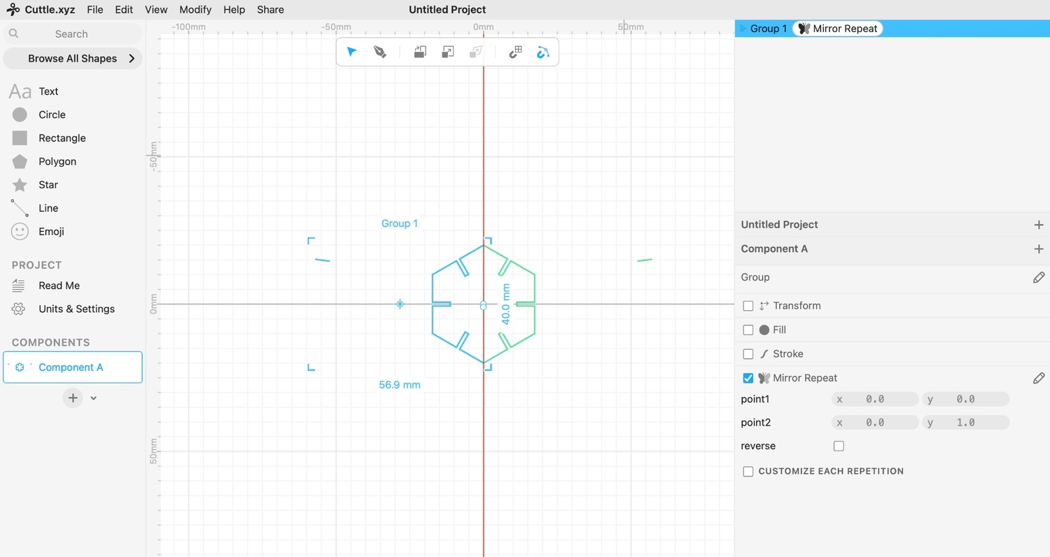
It is a hexagon with 1.6 mm slots on each side. I straigh-up used lines and mirror tool without any parametric constraints. It can slide in with each other creating various shapes.
I exported the final design as an SVG file and transferred it to the Mac connected to our xTool P2S Laser Cutter.
I used wood with a thickness of 1.5 mm and configured the laser to 40% power and 16 speed.
These parameters ensured clean cuts without burning the edges.
I selected the cutting mode within the software and initiated the process.
Here’s a photo of the laser cutting stage:
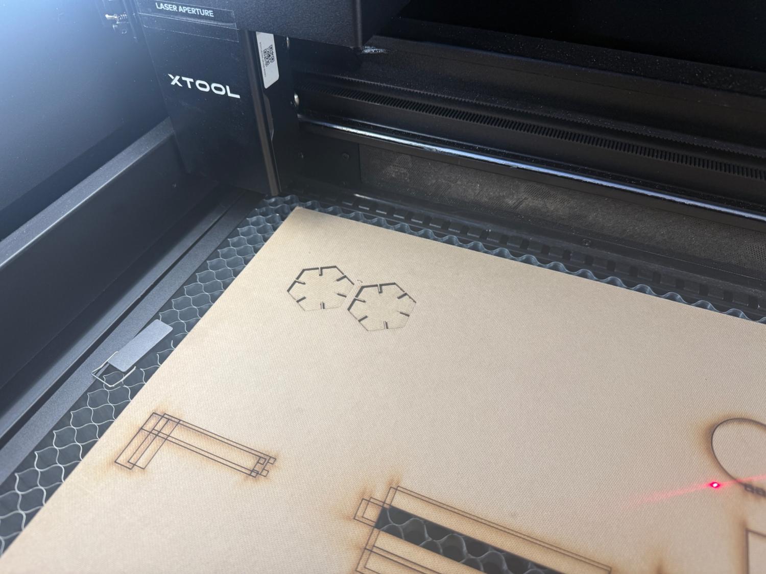
And the cutting process in action:
*Cutting process on Xtool P3Kerf
I realized that the hexagon parts that I laser cut were too hard to slide into each other and that is when I realized that I did not put kerf into considiration.
Kerf is the amount of material that a laser cutter removes while cutting. Because the laser beam has a small thickness, every cut is slightly wider than the line you draw. So if you do not account for kerf, your parts may become:
- loose (if kerf removes too much)
- too tight (if you overcompensate)
To determine the average kerf, I designed a simple square with a 20mm side and cut it 3 times to calculate the average kerf. I measured three kerf values: 0.12 mm, 0.08 mm, and 0.10 mm, which averaged to 0.10 mm.
For the first piece, the cut result measured 19.76 mm, producing a kerf of 0.12 mm since there are 2 sides of a square.
For the second measurement, the cut piece was 19.84 mm, indicating a kerf of 0.08 mm.
Finally, the third piece, the cut result was 19.80 mm, producing a kerf of 0.10 mm.
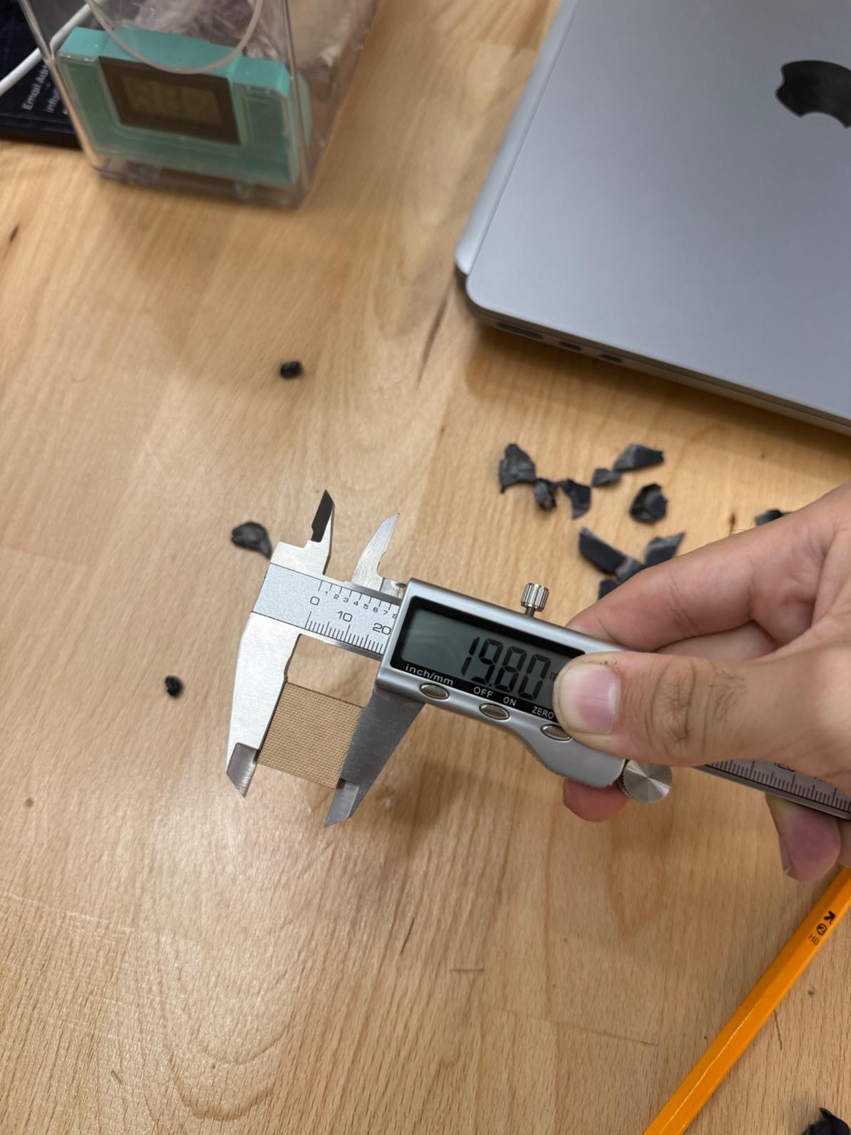 *Photo of the 3rd cut and its measurment.
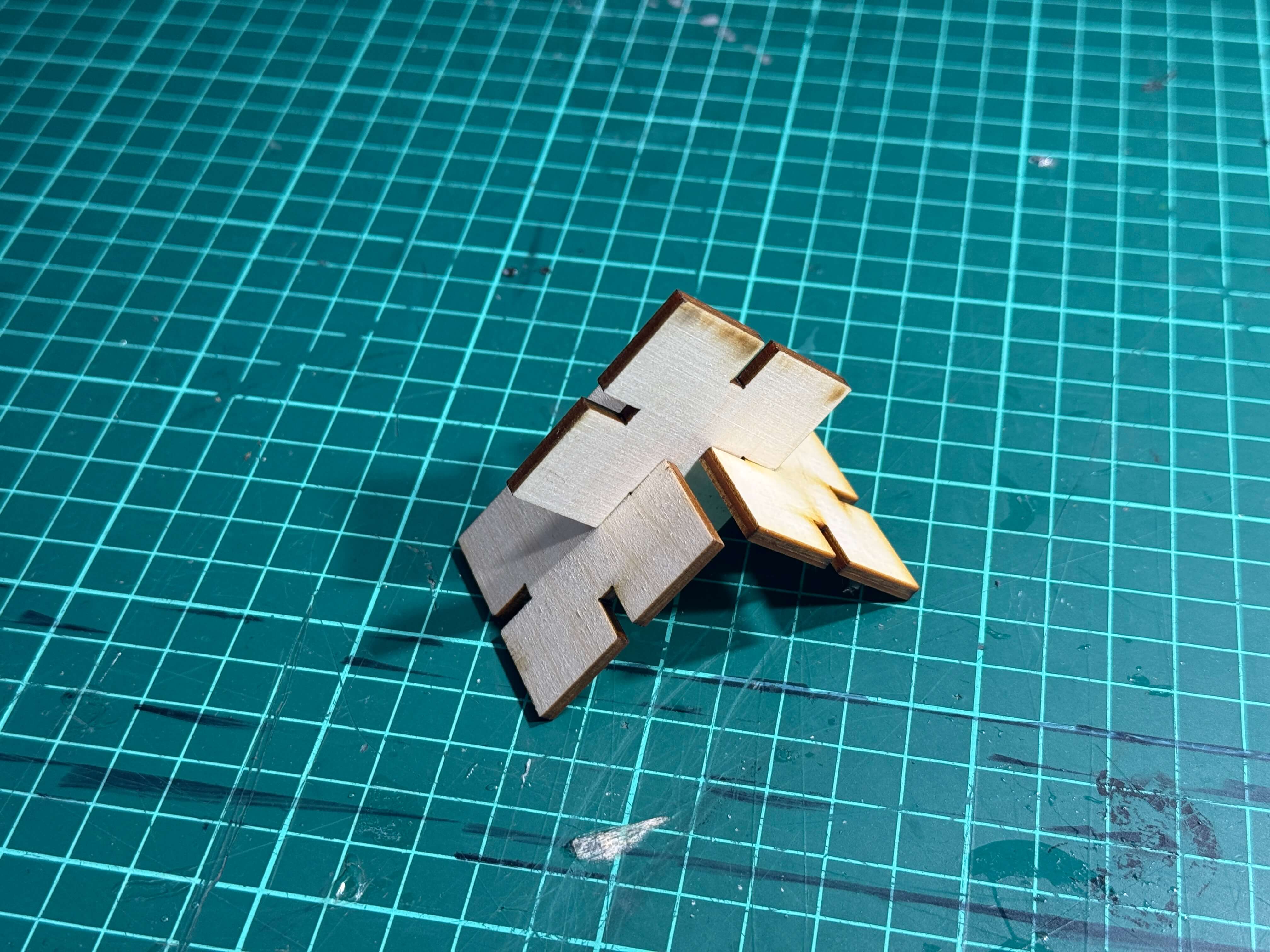
Hexagon with the Calculated Kerf Value:
I applied the calculated kerf value directly to my slot dimensions by increasing the slot width by the kerf value on each side. I cut the hexagon again and here is the video of it creating a snug press fit indicating a good calculation of the kerf value:
*Press fit.Photo of The Finished Hexagon
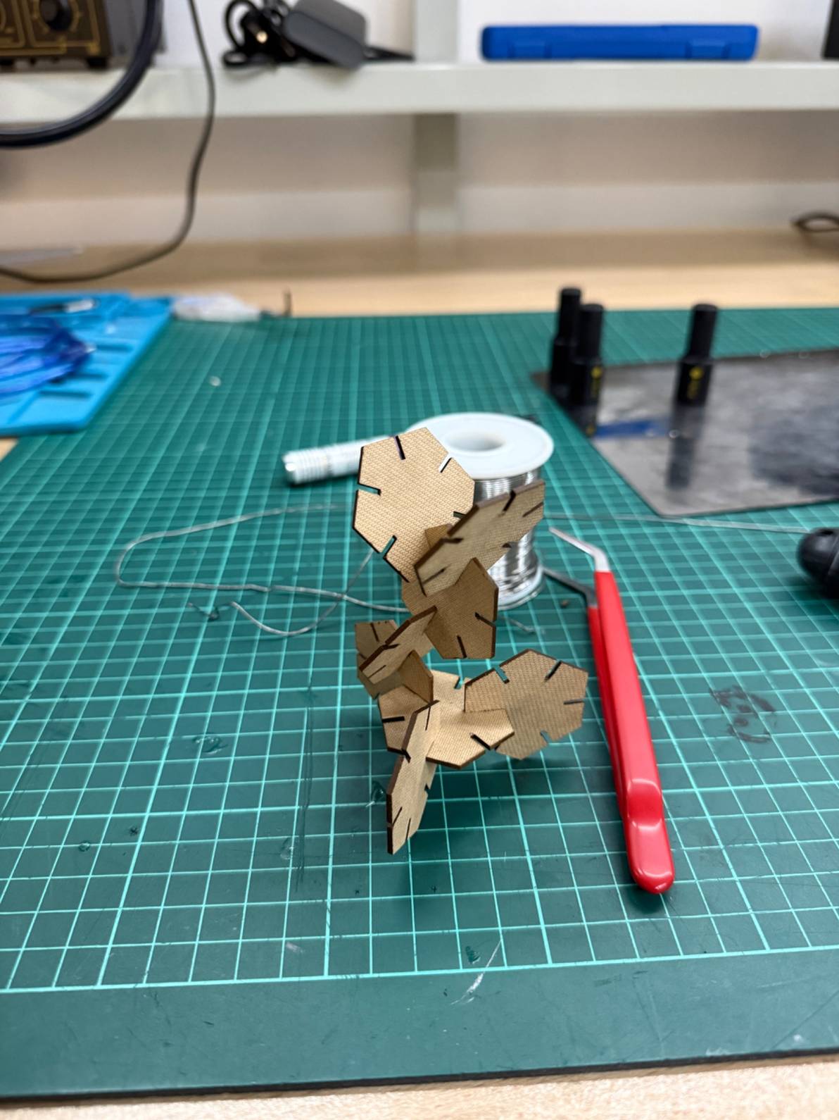
Here is an example way that you can stack up the cut hexagons:
Parametric Construction Kit
For the parametric construction kit I have decided to do a desk organizer without a top panel that you could easily change its dimensions thanks to its parametric constraints and add different compartments.
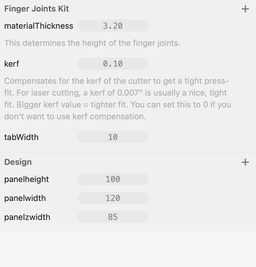
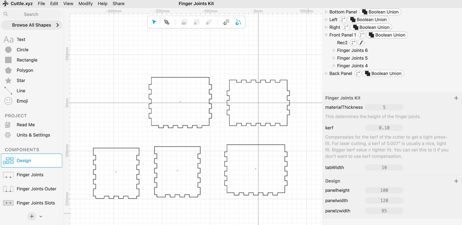
First, I found a cool ready to use parametric finger joints kit and imported to my design. Link to the Kit
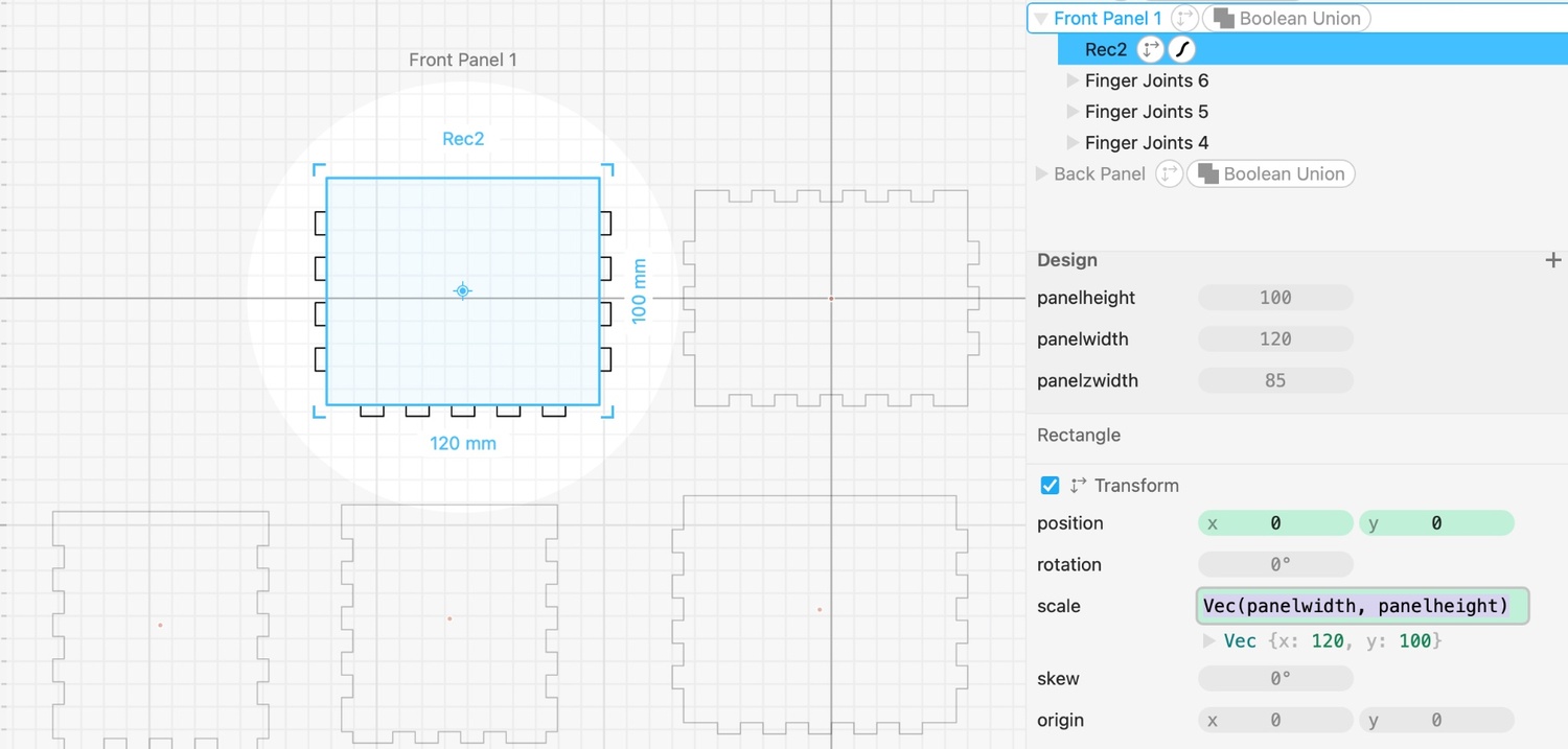
This finger joints kit had already 3 parameters defined so I edited them according to my own design. I added 3 more parameters in the design as you can see below:
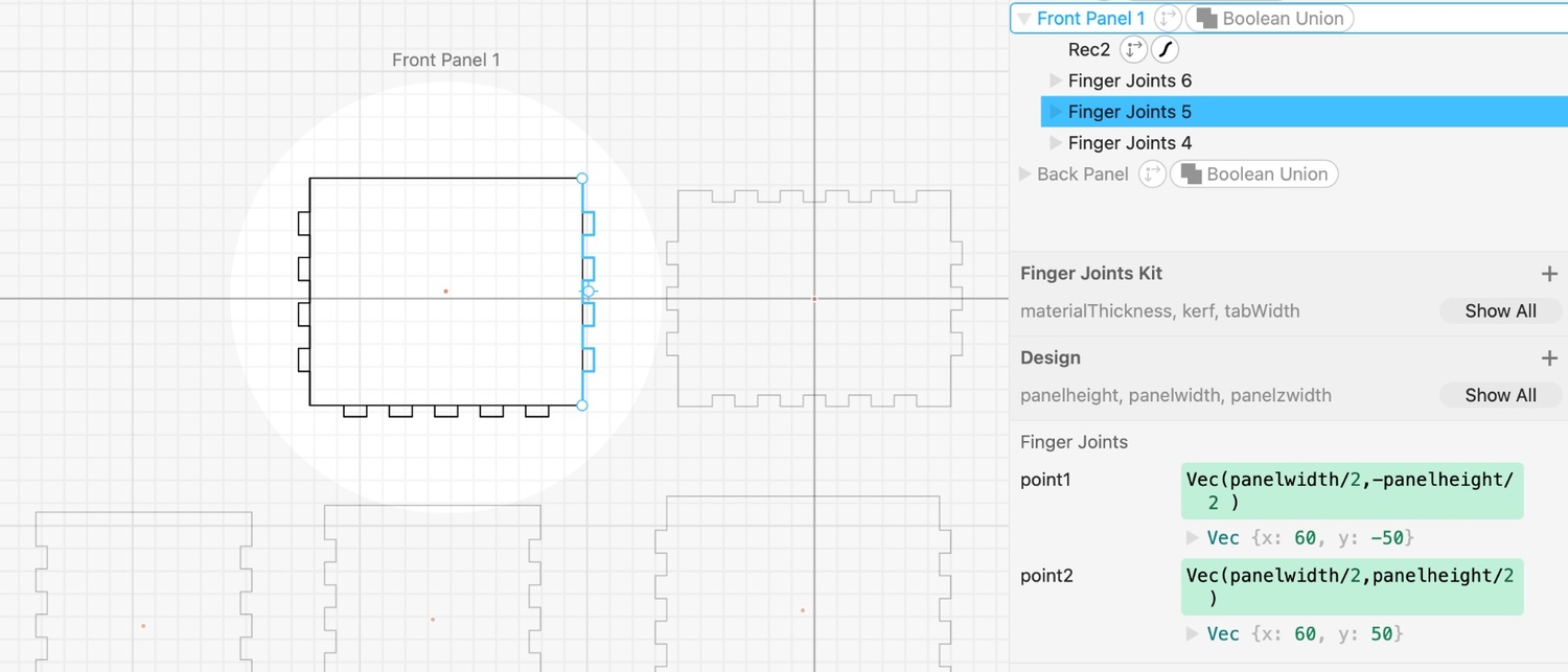
I connected panels’ sizes and the finger joints’ points regarding the parametric values that I created before this step. After each panel don’t forget to group joints and panels toghether. Here is an example from one of the front panel’s finger joints. You can see the that the points of the finger joints are connected to the parametric values, just like front panel itself, so as the parametric values increase/decrease the finger joints and actual panel’s size change accordingly.
The completed design of the parametric construction kit can be seen below:
Cutting the Parametric Construction Kit:
I went with the exact same steps and configurations while cutting the hexagon using the xTool. I used a 3mm wood panel this time but I had some problems. Since the material was thicker and I forgot to change the speed and power accordingly, first cut didn’t even fully go through the panel.
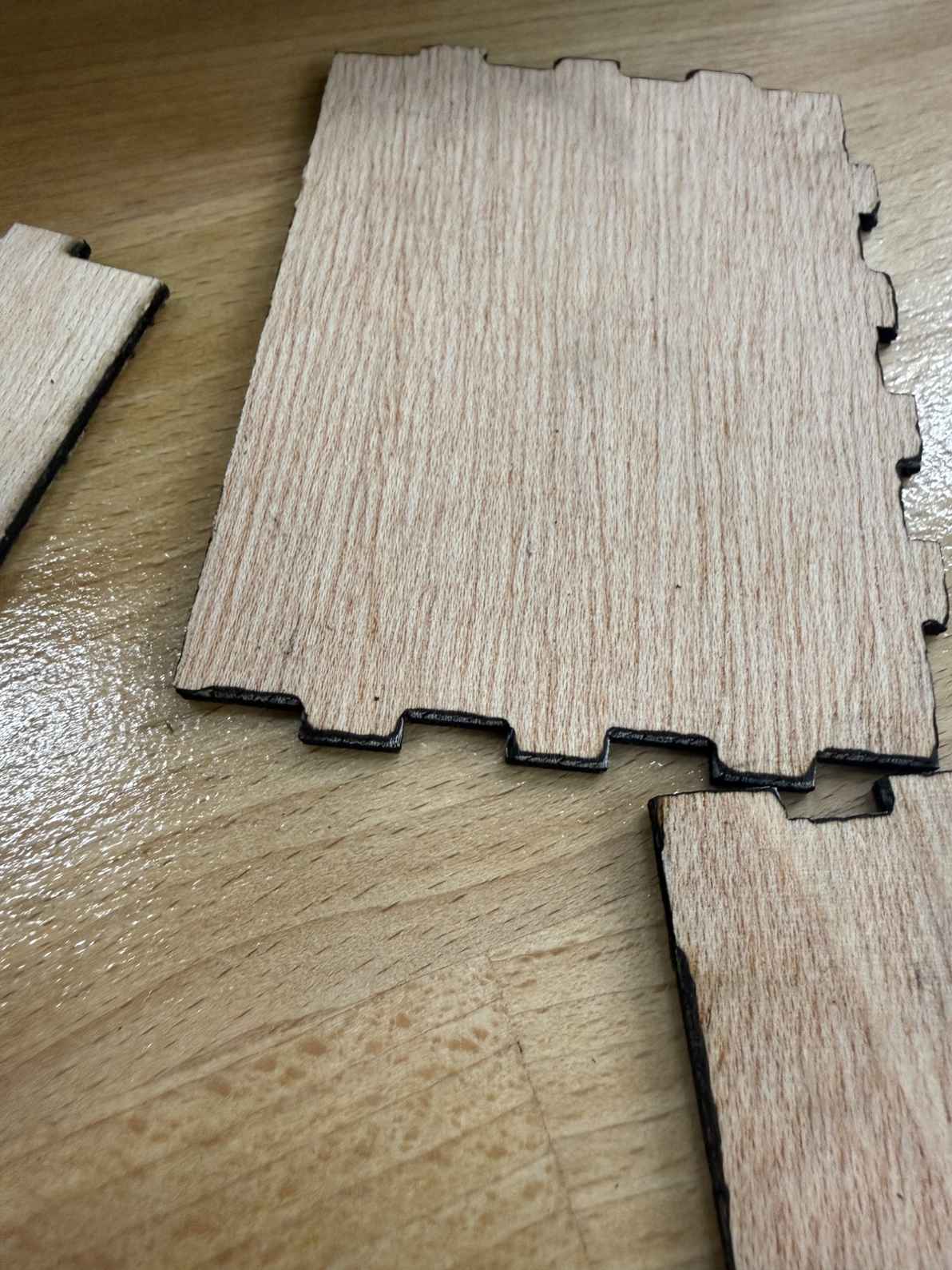
In the second cut I set the values speed at 25 and power at 75. This time the laser went through but it made sides of the cut uneven (destroying the perfect fit) and burnt partially. Here is the close up photo:
After examining the sides, I went for a cut with speed at 30 and power at 80. Even though it was not perfect here is the photo of the construction kit:
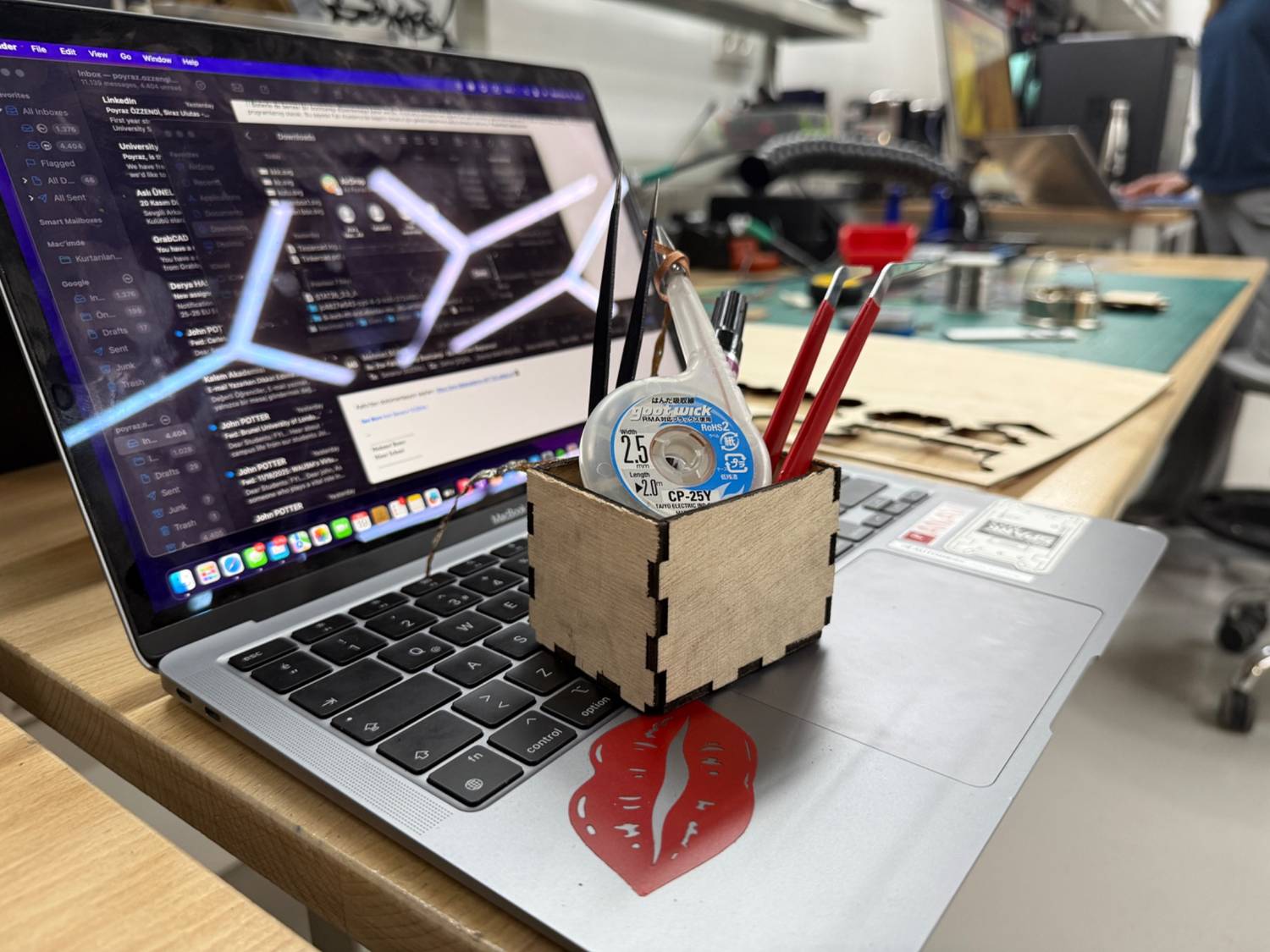
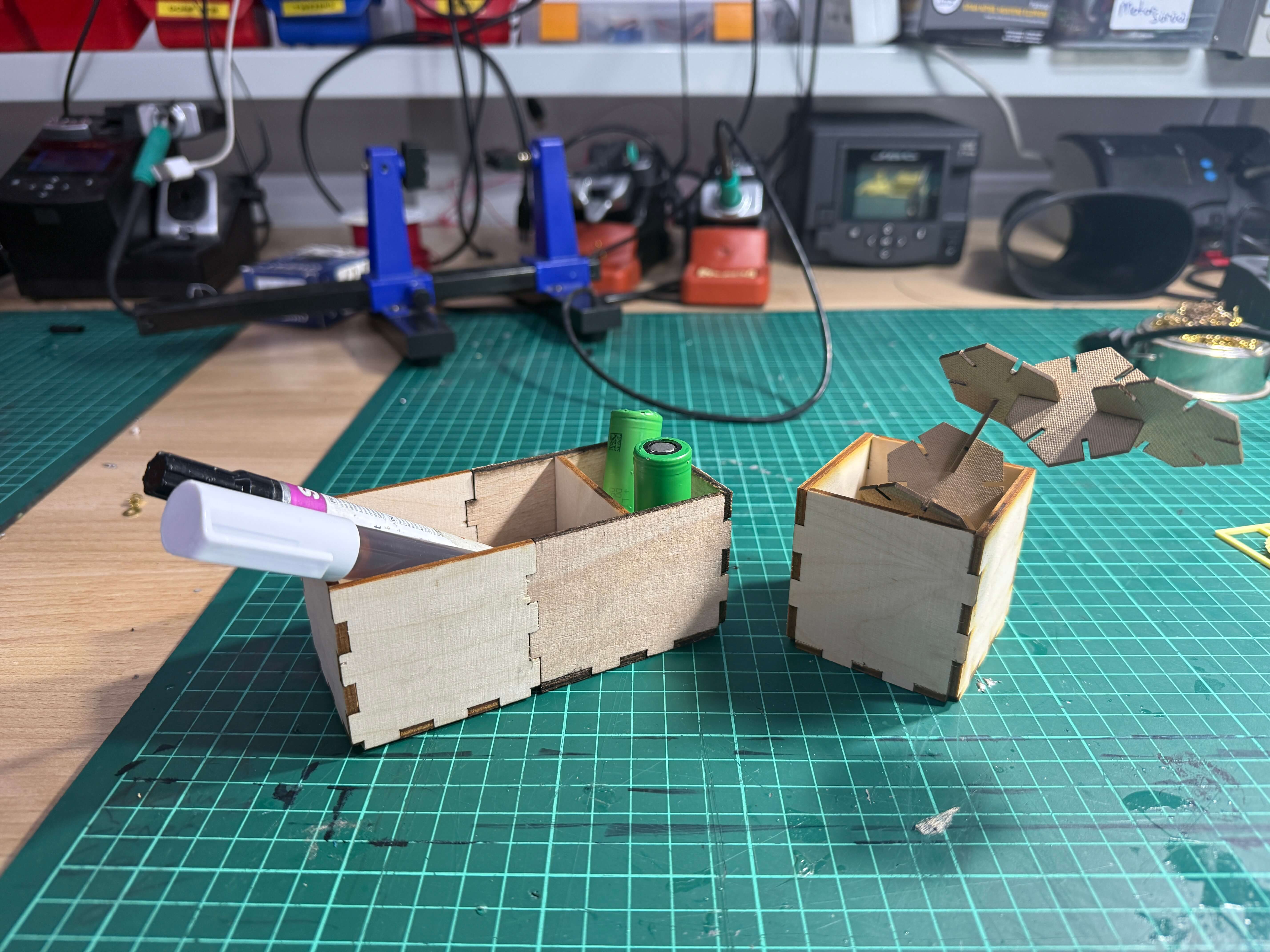
Since I will be using them, I wanted to create another organizer with increased height. Also, increase the old organizer’s lenght and add a divider. This time I changed the power to 100 and speed to 50. This values ensured me a perfect clean cut. (As you can see the difference between the old and the new cut.)
Other Parametric Construction Kit With OTTO:
To test out another parametric design environment I used OTTO a multimodal parametric design environment that is an ongoing research project at our lab for the last year.
https://idealab-design-environments-group.github.io/otto-v2/
I wanted to do squares that linked with each other using press fit joints so I got help form on of my friends who are currently on this research project. Basically parametric design process was similiar to CuttleXYZ but this time with code.
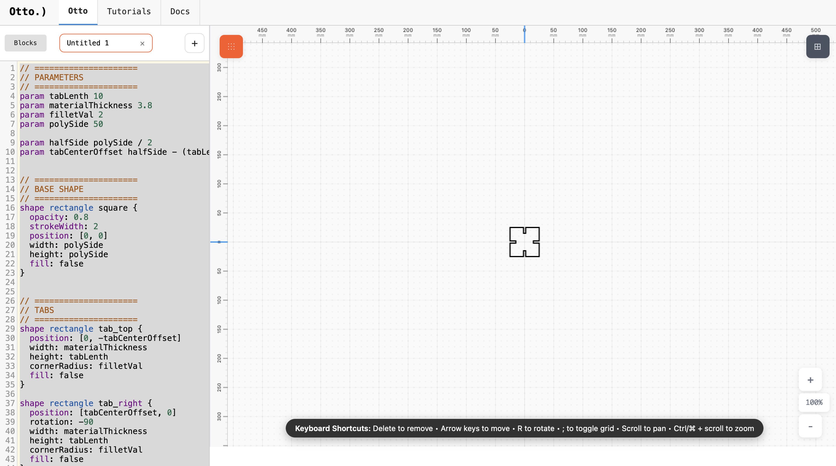
I exported the file as .svg and imported to Xtool’s application. On the xtool’s appliccation I duplicated these squares so that I could have multiple pieces that I could connect. Laser cut with the same perfected parameters that I used before since i was still using 3mm plywood.
Vinyl Cutting on Cricut Maker 3
1) Creating the Design
I began by connecting a Mac computer to the Cricut Maker 3 and launching the Cricut Design Space software. On a blank canvas, I created my own design: a multi colored “Fab In The Sun” text.
Design:
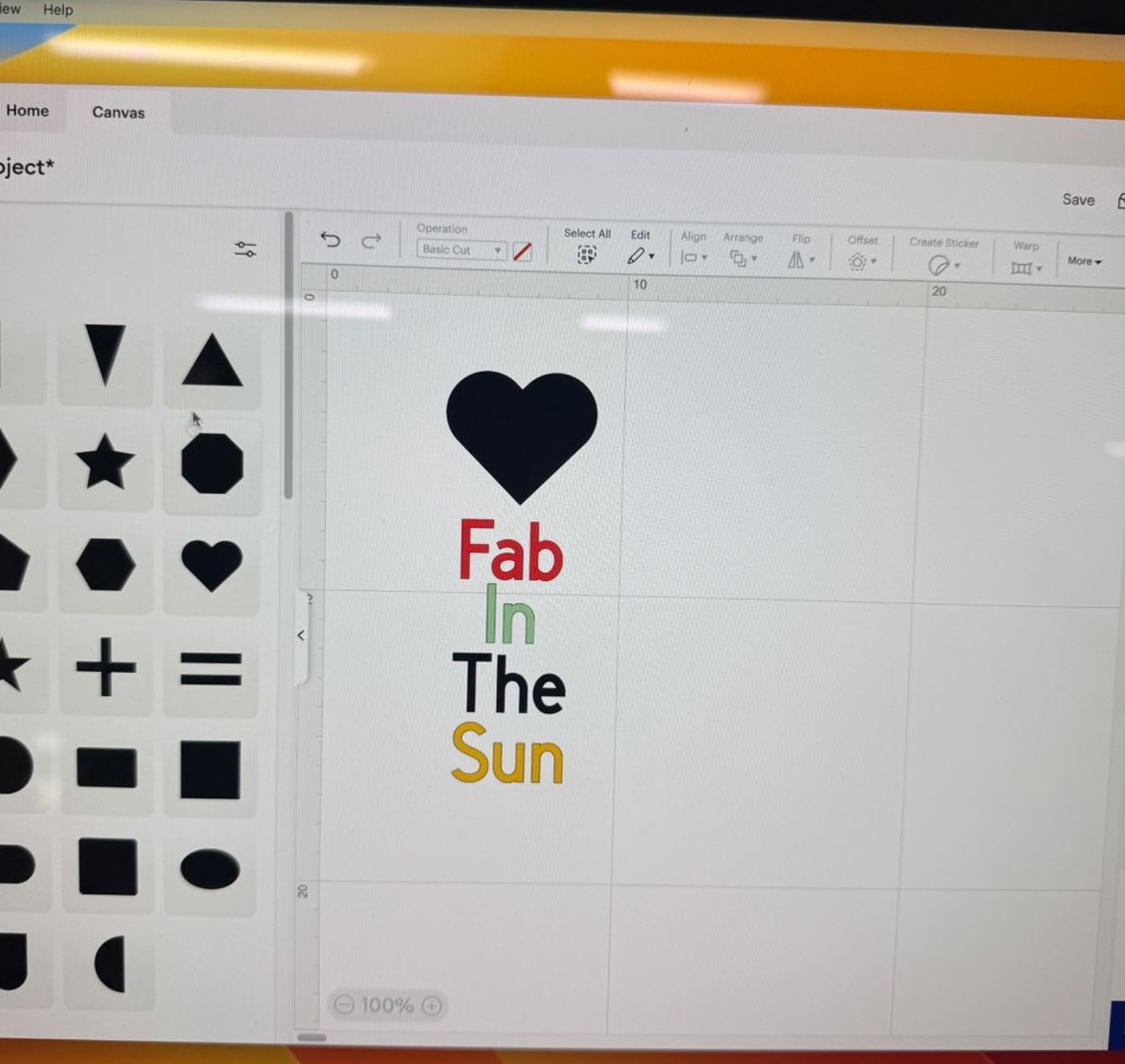
The design included four individual layers of text, each representing a separate vinyl color.
2) Cutting the Vinyl
To produce the final cut, I followed these steps:
- Positioned the vinyl sheet on the Cricut cutting mat.
- Used a roller to press down the vinyl, ensuring there were no air pockets.
- Loaded the mat into the Cricut Maker 3.
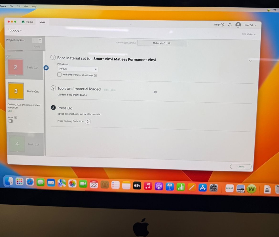
- Selected the proper material setting inside Design Space.
- Clicked “Make It” to begin cutting.
Since my project had four layers, I repeated this process four times with different vinyl colors.
Here’s what some of the on-screen cutting instructions looked like:
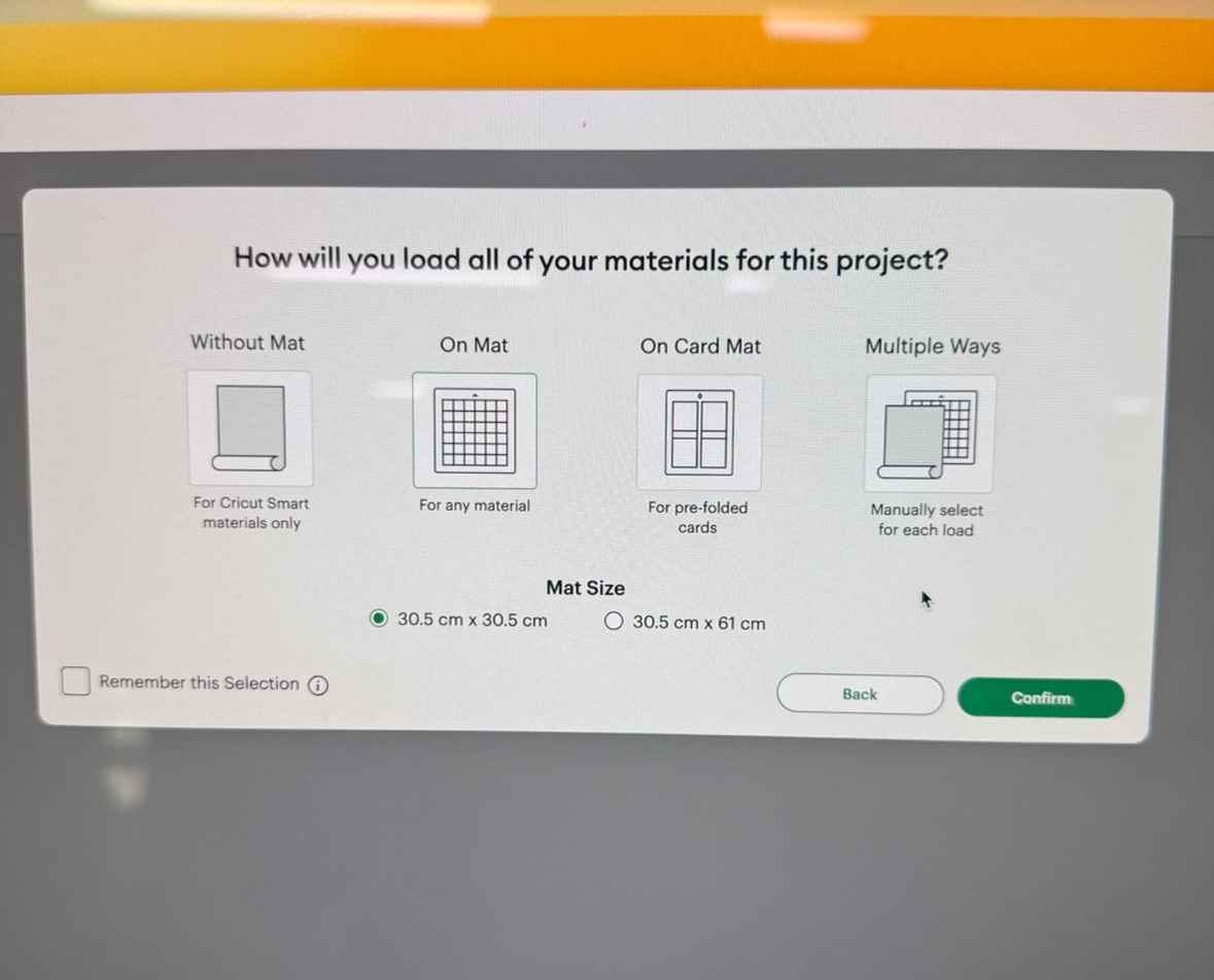
Video of the cutting process:
*Cutting process on Cricut Maker 3.3) Final Sticker
Once all layers were cut, I carefully removed the extra vinyl (weeding) and aligned each color layer.
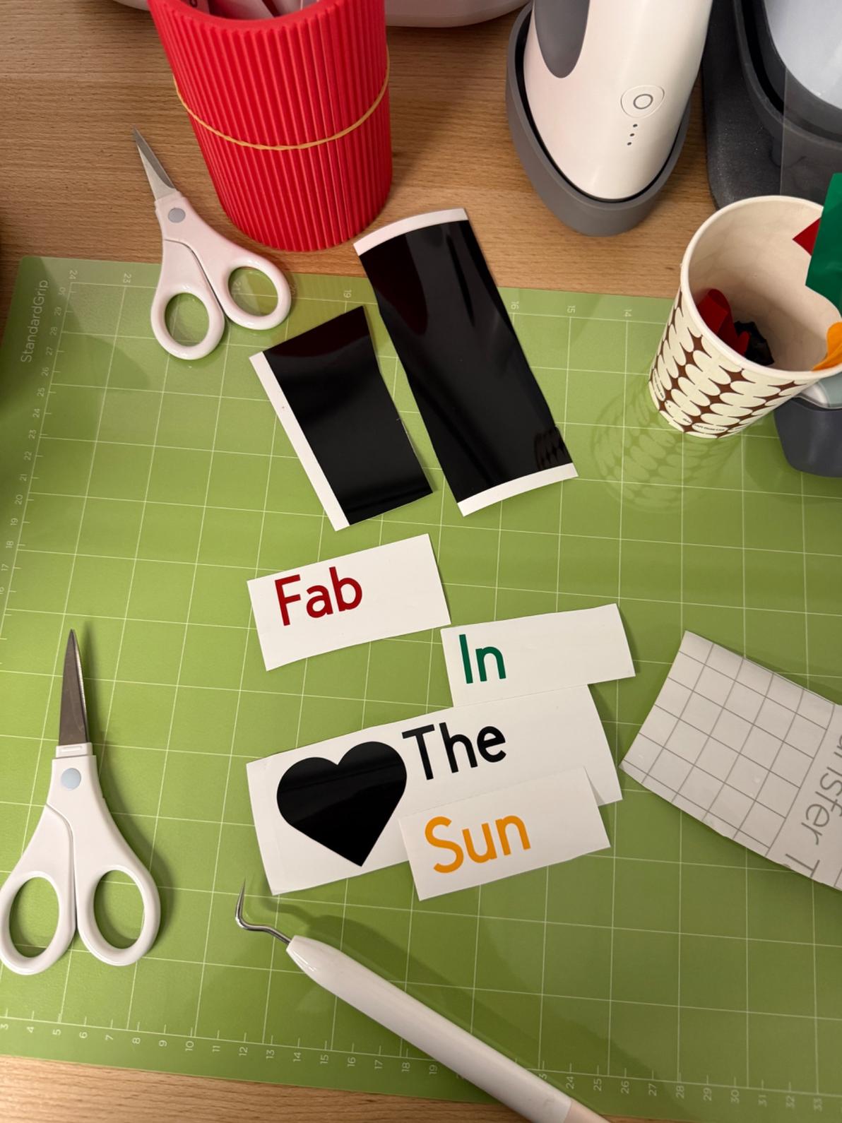
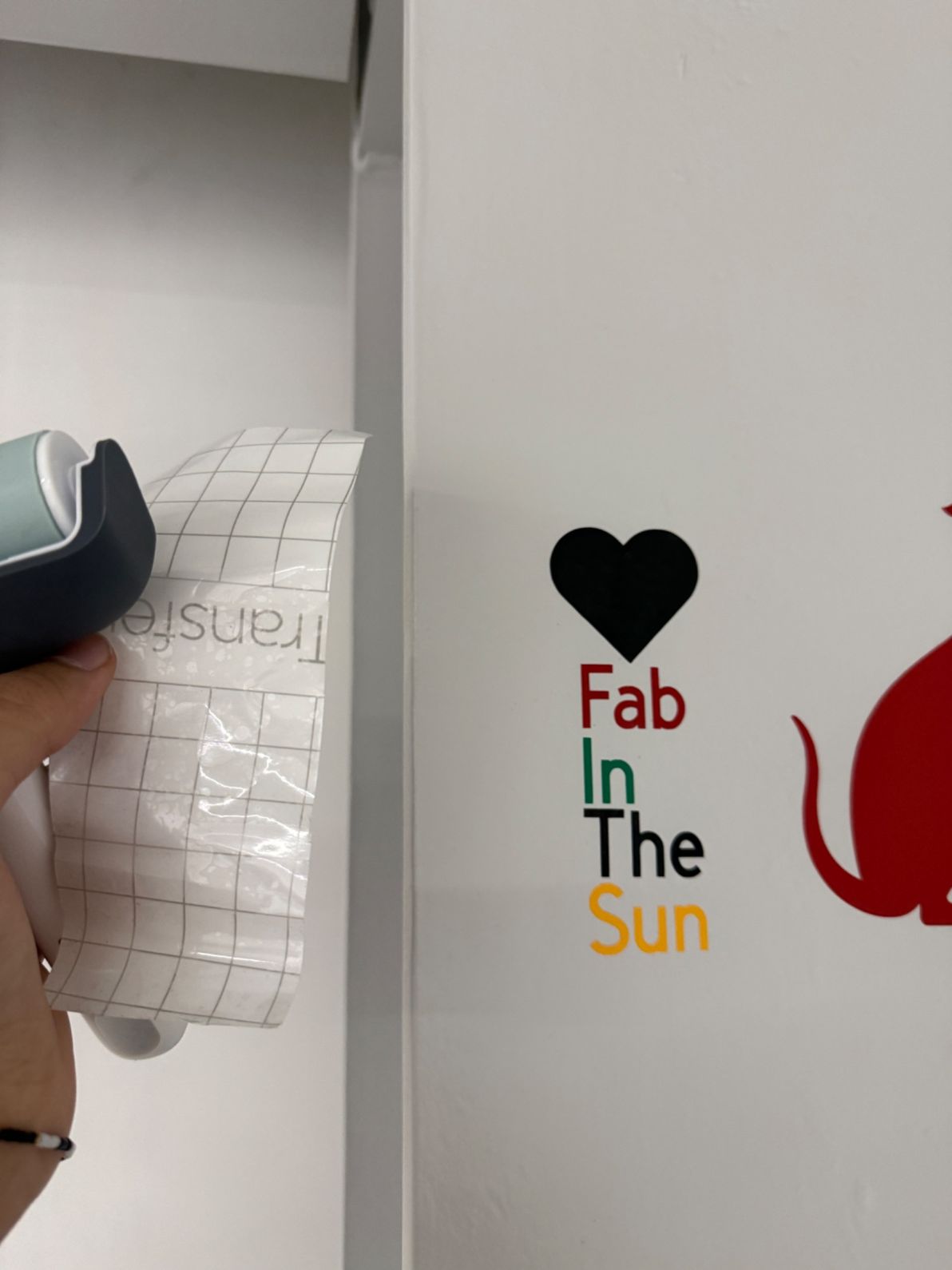
After aligning each layer I used a transfer tape to transfer the vinyls on seperate bases to one base.
The result was a multi-layered vinyl sticker “Fab in The Sun”:
Reflection
This week showed me how important kerf compensation and parametric design are for accurate laser cutting. Measuring and applying the kerf value and experimenting with different laser settings taught me how sensitive results are to material thickness.
Working with parametric tools made it easy to iterate and modify designs quickly.
The vinyl cutting part also helped me understand layer-based design, alignment, and transfer techniques, especially when working with multi-color graphics.
Overall, this week emphasized precision, iteration, and adapting workflows to different computer-controlled cutting tools.