This week’s assignment was focused on embedded programming using a microcontroller.
The main goals was to learn how to:
- browse and understand a microcontroller datasheet
- write and test a program for an embedded system
- interact with local inputs/outputs
- communicate with remote wired/wireless connections
- upload working code and show a functional result
For my individual assignment, I used an Xiao ESP32 C3 development board, soldered male pin headers, and tested it on a breadboard by blinking an LED, then upgrading the circuit with a button input + Serial communication.
Hero Shots
Group Assignment
Group assignment page:
https://week-4-group-assignment-e3c295.fabcloud.io
Tools & Materials
Hardware
- Xiao ESP32 C3 Dev board
- Male pin headers
- Breadboard
- LED
- Resistor (220Ω)
- Push button
- type-c cable (for power + programming)
- Macbook Air
Software
- Arduino IDE
- ESP32 board package
Microcontroller Datasheet Research (ESP32)
Before writing code, I browsed an ESP32 datasheet (https://documentation.espressif.com/esp32_datasheet_en.pdf) to understand what I am programming and what features the board offers. This documentation was overwhelming for me.
I also got help from this more user friendly guide for Xiao ESP32 C3:
- Seeed Studio XIAO ESP32C3 Getting Started:
https://wiki.seeedstudio.com/XIAO_ESP32C3_Getting_Started/
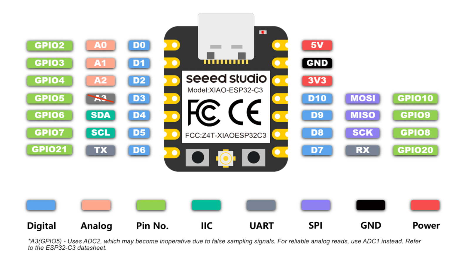
Key features:
- GPIO pins: ESP32 has many programmable pins used for input/output
- PWM support: allows dimming LEDs and controlling motors
- Wi-Fi + Bluetooth: built-in communication features
- Multiple power modes: useful for battery powered projects
- 3.3V logic: important because ESP32 pins are not 5V tolerant in most cases
What I learned from the datasheet:
- ESP32 pins can behave differently depending on boot mode
- Some GPIO pins are “special” pins used for booting, flash programming, etc.
- ESP32 is designed for projects that need both processing + wireless communication, which makes it suitable for my final project plans.
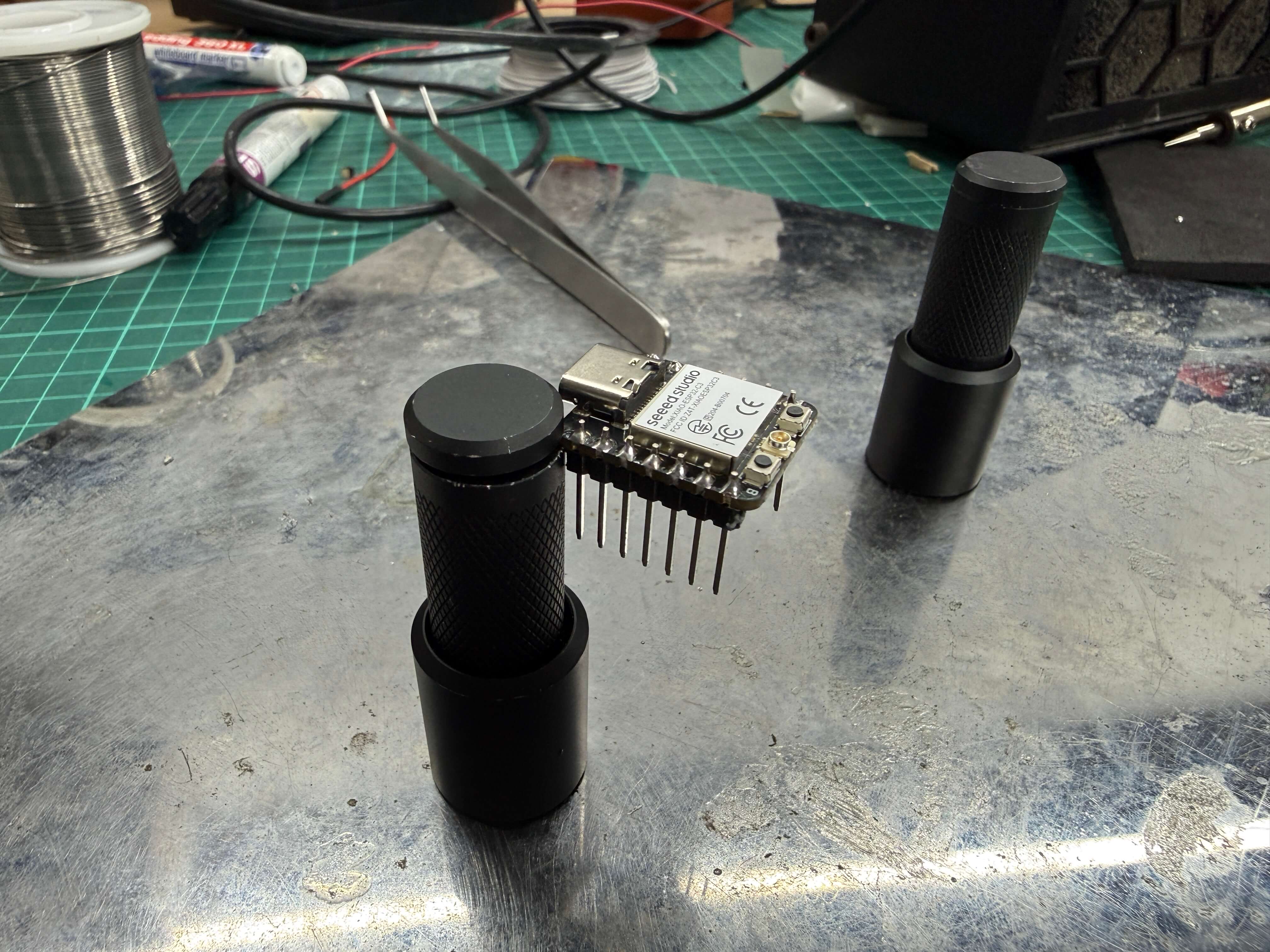
Preparing the ESP32 Board (Soldering Headers)
My ESP32 board came without soldered pins, so I first had to solder male pin headers.
Steps I followed:
- Placed the male pin headers into the breadboard (to keep them straight)
- Positioned the ESP32 board on top of them
- Soldered each pin carefully, checking alignment constantly
- Inspected solder joints to ensure:
- no bridges between pins
- shiny and solid connections
- strong mechanical stability
This step was important because without headers, I couldn’t reliably connect the board to a breadboard for prototyping and programming.
Checking the solder:
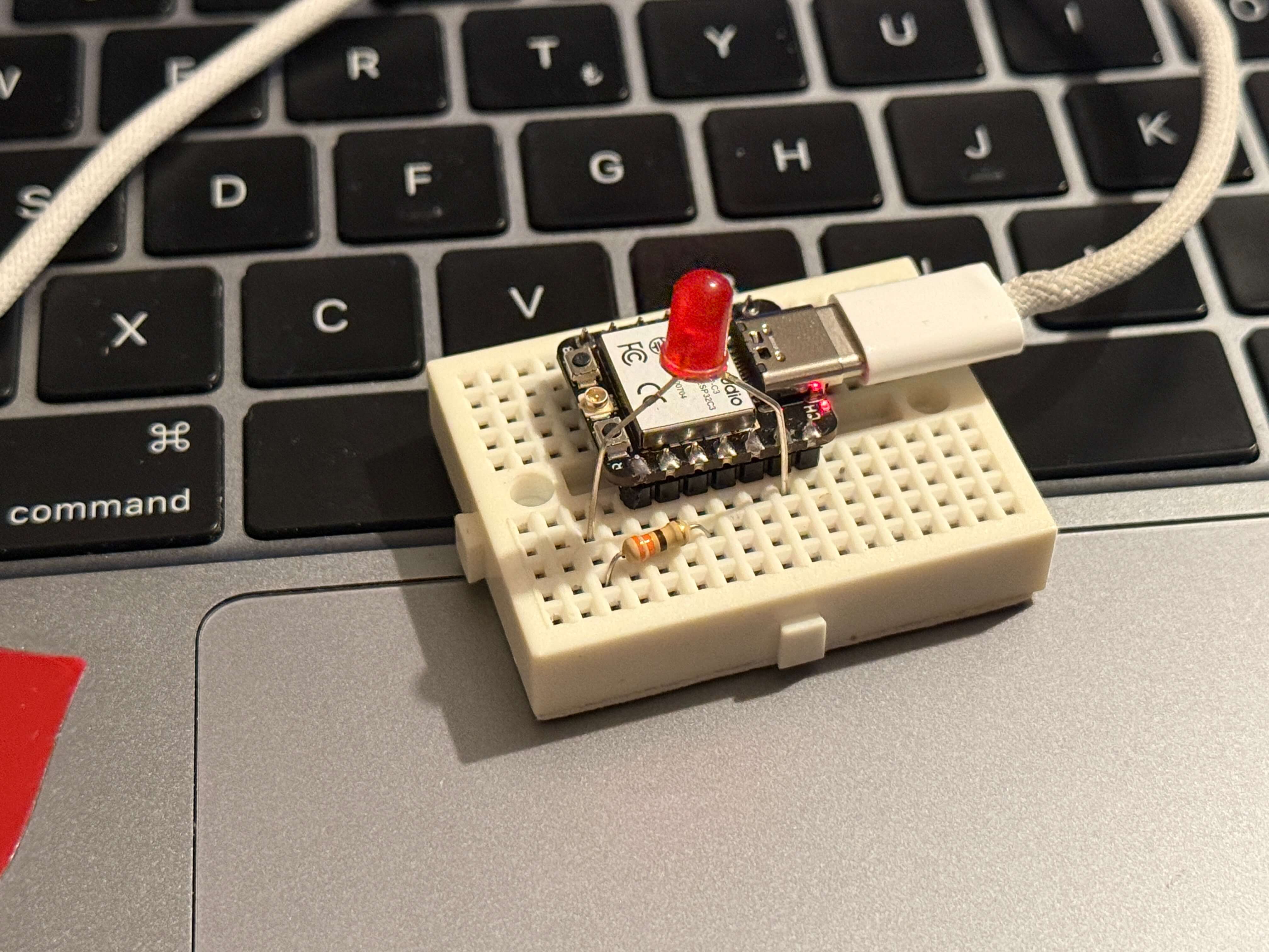
Circuit 1 — Blink LED Test (Local Output)
After soldering, I moved on to a simple embedded test: blinking an LED.
Circuit setup
- One LED leg (anode) connected to a GPIO pin
- The other LED leg (cathode) connected to GND
- A resistor was added in series to protect the LED
My wiring logic:
- The ESP32 turns a pin HIGH → LED turns ON
- The ESP32 turns a pin LOW → LED turns OFF
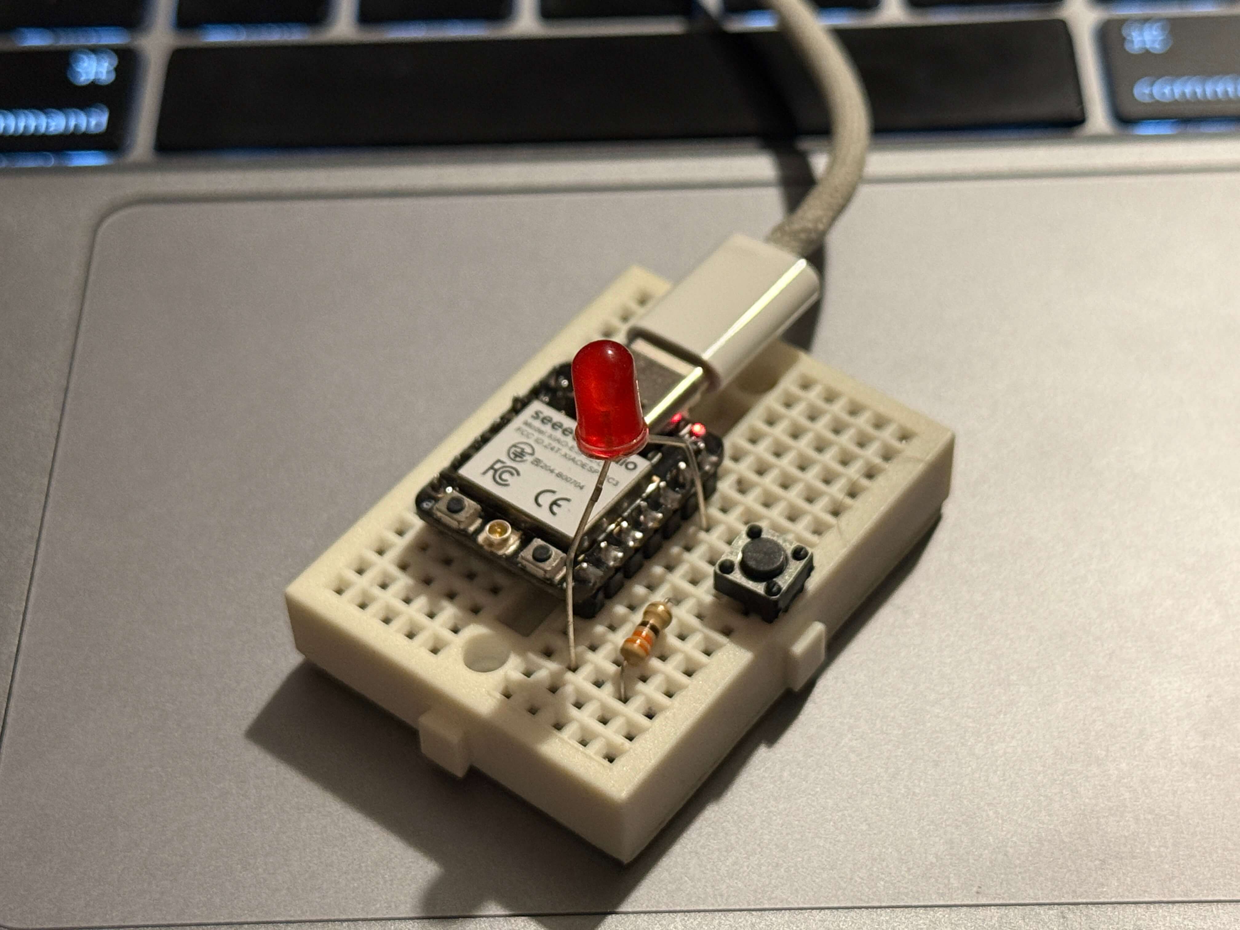
Circuit 2 — Button Input + Serial Communication (Input + Output + Wired Communication)
After confirming the ESP32 worked with the blink test, I upgraded the circuit to include:
Local input: push button
Local output: LED
Wired communication: Serial Monitor (type-c)
- In terms of wiring a push button with 2 legs is added. One of its leg to a gpio pin and the other is to ground.
Circuit logic
- When I press the button → ESP32 reads the input
- ESP32 turns the LED ON/OFF
- ESP32 prints the state to Serial Monitor
Programming Process
Installing ESP32 Support in Arduino IDE
To program ESP32 using Arduino IDE, I first installed the ESP32 boards manager.
Steps:
- Open Arduino IDE
- Go to Preferences
- Add ESP32 Board Manager URL (It is in the datasheet)
- Go to Boards Manager
- Install esp32 by Espressif Systems
Then I selected:
- Board: ESP32 Dev Module
- Port: the detected USB serial port
Note: Be sure that you chose the correct board as there are many board to chose from with similar names. At first I did that mistake :P
How Arduino Ide Looks:
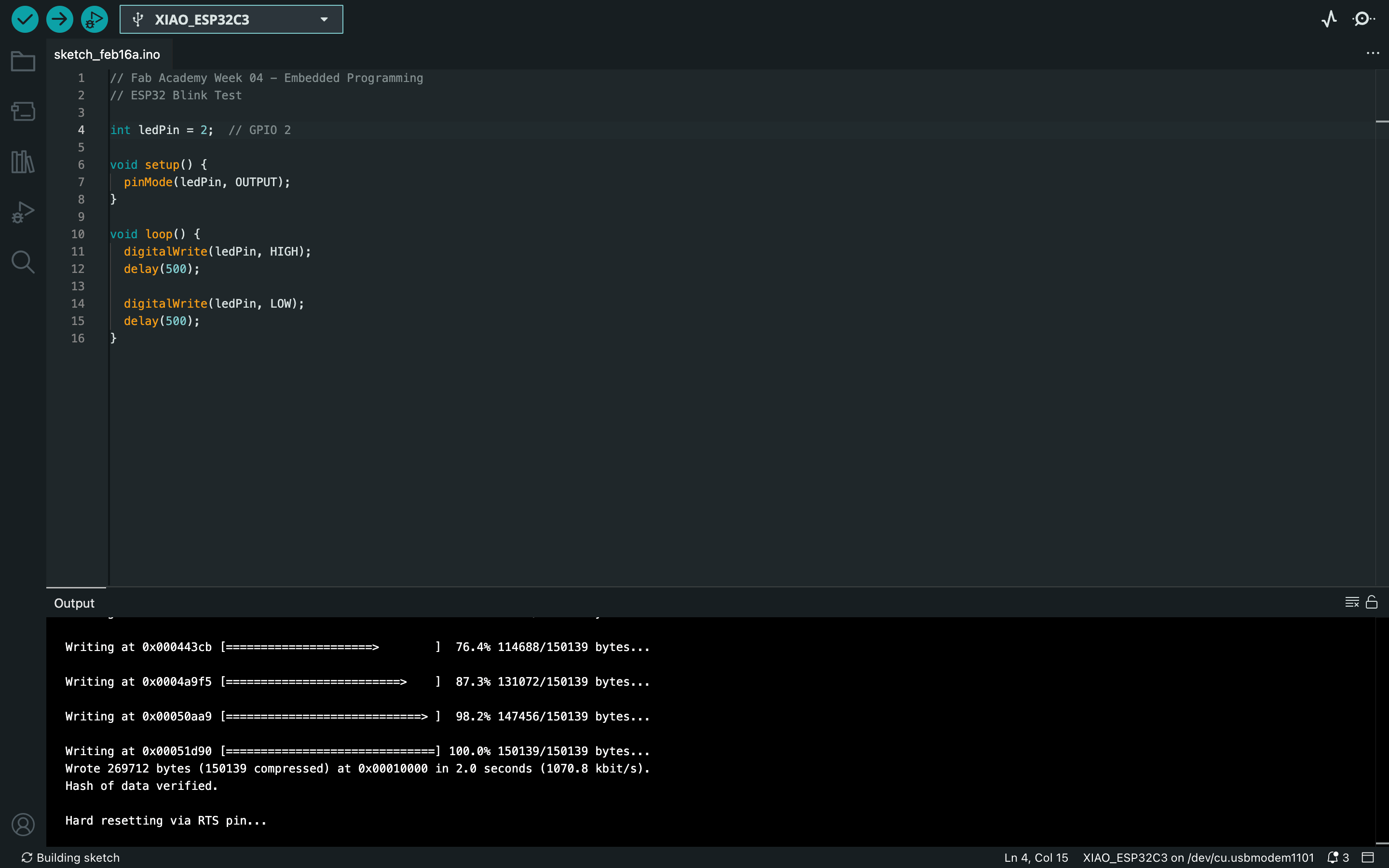
Source Code
Code 1 — Blink LED
// Fab Academy Week 04 - Embedded Programming
// ESP32 Blink Test

int ledPin = 2;  // GPIO 2

void setup() {
  pinMode(ledPin, OUTPUT);
}

void loop() {
  digitalWrite(ledPin, HIGH);
  delay(500);

  digitalWrite(ledPin, LOW);
  delay(500);
}
Code 2 — Button + Serial Communication
// Fab Academy Week 04 - Embedded Programming
// ESP32 Button + LED + Serial Communication

int ledPin = 2;      // GPIO 2
int buttonPin = 4;   // GPIO 4

void setup() {
  pinMode(ledPin, OUTPUT);
  pinMode(buttonPin, INPUT_PULLUP);  // internal pull-up

  Serial.begin(115200);
  delay(1000);
  Serial.println("ESP32 Button + LED Test Started");
}

void loop() {
  int buttonState = digitalRead(buttonPin);

  if (buttonState == LOW) { // pressed
    digitalWrite(ledPin, HIGH);
    Serial.println("Button Pressed -> LED ON");
  } else {
    digitalWrite(ledPin, LOW);
    Serial.println("Button Released -> LED OFF");
  }

  delay(100);
}
Testing and Results
After uploading the codes to the ESP32, the board successfully ran the programs
The LED blinked continuously (Circuit 1)
Video:
The button correctly controlled the LED (Circuit 2)
Serial Monitor printed live status messages (Circuit 2)
Video:
Serial communication:
This confirmed:
- the ESP32 was properly powered
- my header soldering was correct
- my wiring was correct
- I could compile and upload code successfully
Reflection
This week helped me understand the full process of embedded programming from scratch:
- hardware preparation (soldering headers)
- wiring and testing on a breadboard
- programming through Arduino IDE
- writing and uploading code
- basic output behaviors
- adding input + communication for a more complete embedded system test
The biggest takeaway for me is that embedded programming is not only “writing code”, but also combining hardware setup + correct wiring + understanding what the microcontroller is capable of.
This was an important foundation week because I will need these skills when I start building more advanced outputs (RGB LEDs, displays, and sound) for my final project.