Introduction
This week focused on designing, machining, and assembling a large object using a CNC router.
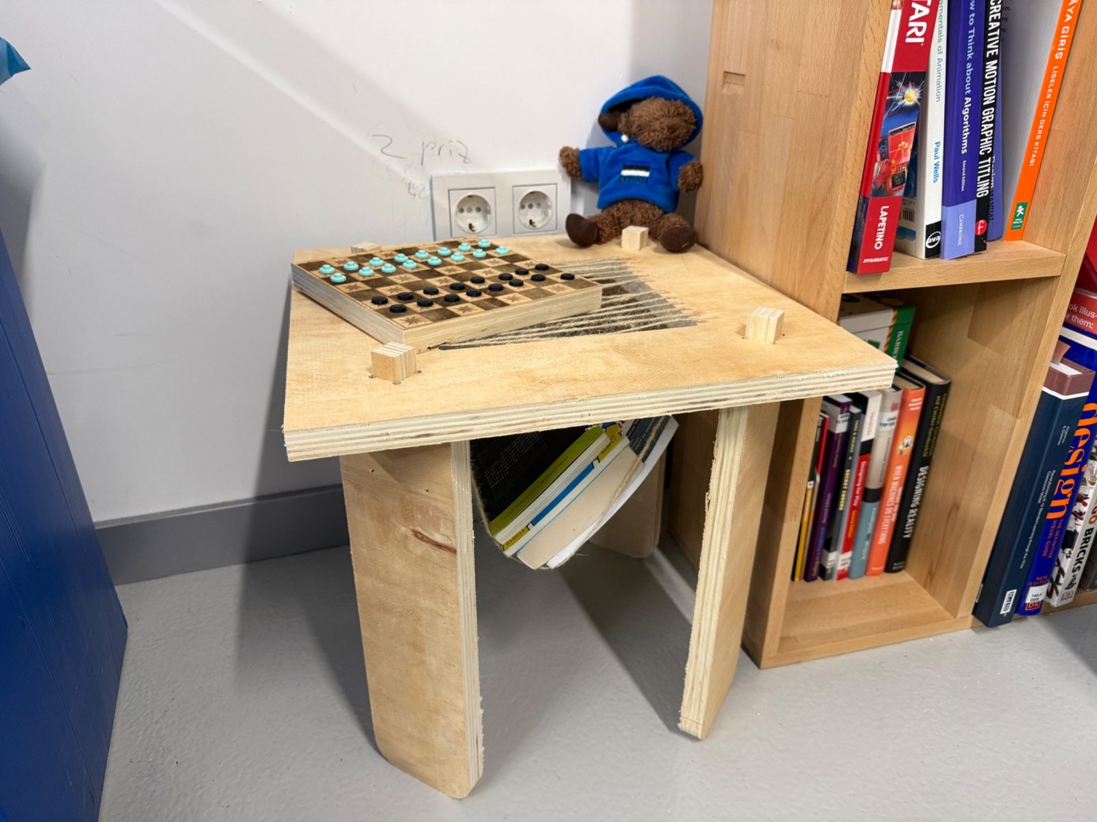
For my individual project, I designed and fabricated a compact plywood table with a central woven opening. This middle section is not only a visual element, but also gives the table a secondary function as a book or magazine holder.
The workflow for this week covered the complete process from design to CAM preparation, machine setup, machining, assembly, and final use.
Group Assignment
Group assignment page:
(paste your group assignment link here)
Tools and Materials
Hardware
- Locally Produced Large format CNC router
- 2cm Plywood sheet
- Flat end mills
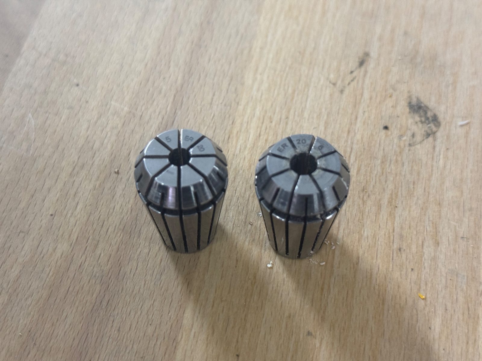
- Collets
- Screws for fixturing
- Drill / screwdriver
- Jute rope for the woven middle section
- XTool p3 Laser cutter for the checkerboard made from leftover material
- Vacuum or brush for cleaning
- Sandpaper for light finishing
Software
- Fusion 360
- VCarve Pro
- CNC machine control software
Hero Shot
Assignment Overview
The assignment for this week was to make something big using design, CAM preparation, CNC machining, and assembly.
My final product is a compact plywood table. The design consists of:
- one top panel
- four legs
- slot-based joints between the top and the legs
- a woven center opening
- a built-in book or magazine holder function
Design Process
Initial idea
I started with the idea of making a small table that could fit into a room without taking too much space. I also wanted the table to have an additional purpose, so instead of leaving the center as a straight plane, I developed it into a section that could hold books or magazines using a woven mesh.
The design idea was based on keeping the geometry minimal while still making the object visually interesting and structurally useful.
Parametric design in Fusion 360
I designed the object in Fusion 360. I kept the model parametric so the dimensions could be changed easily if the plywood thickness or the overall scale changed.
Example parameters:
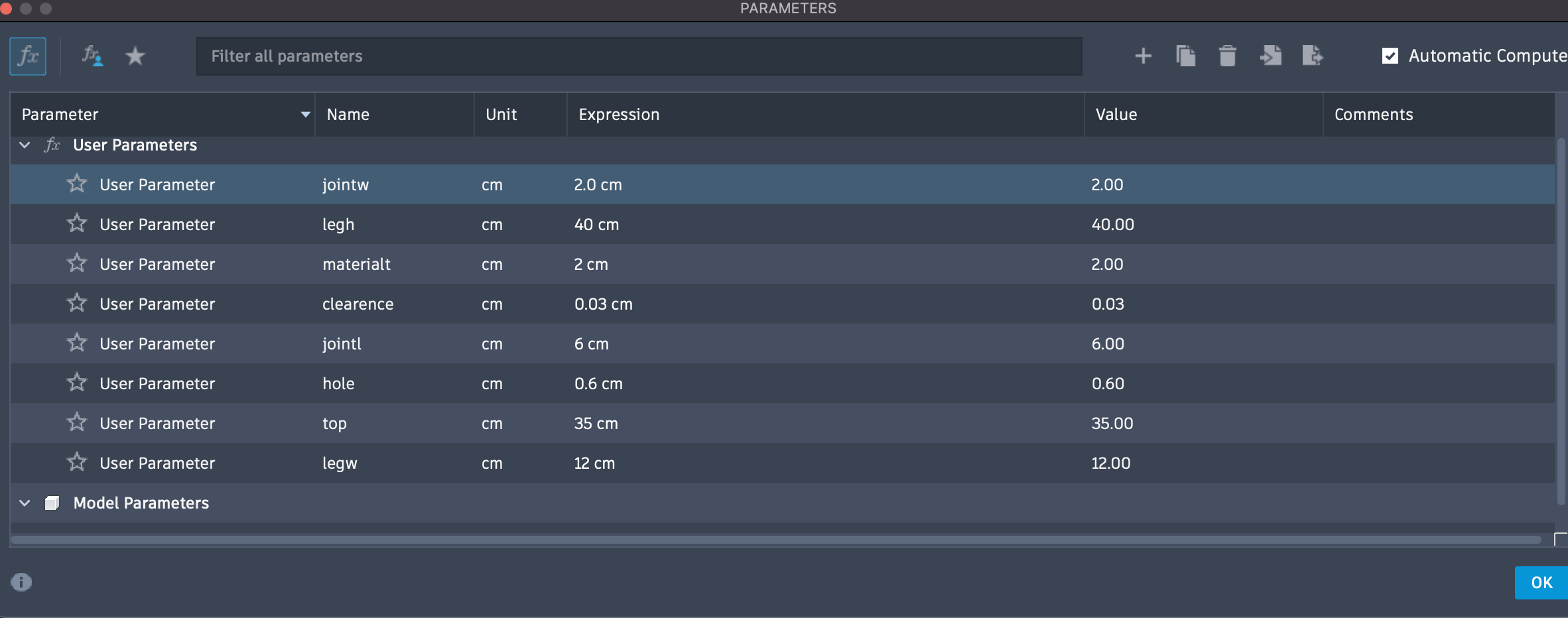
The main things I considered during the design were:
- overall table width and height
- slot widths for the leg joints
- material thickness
- fit between the top and the legs
- the geometry of the central opening
- CNC limitations on internal corners
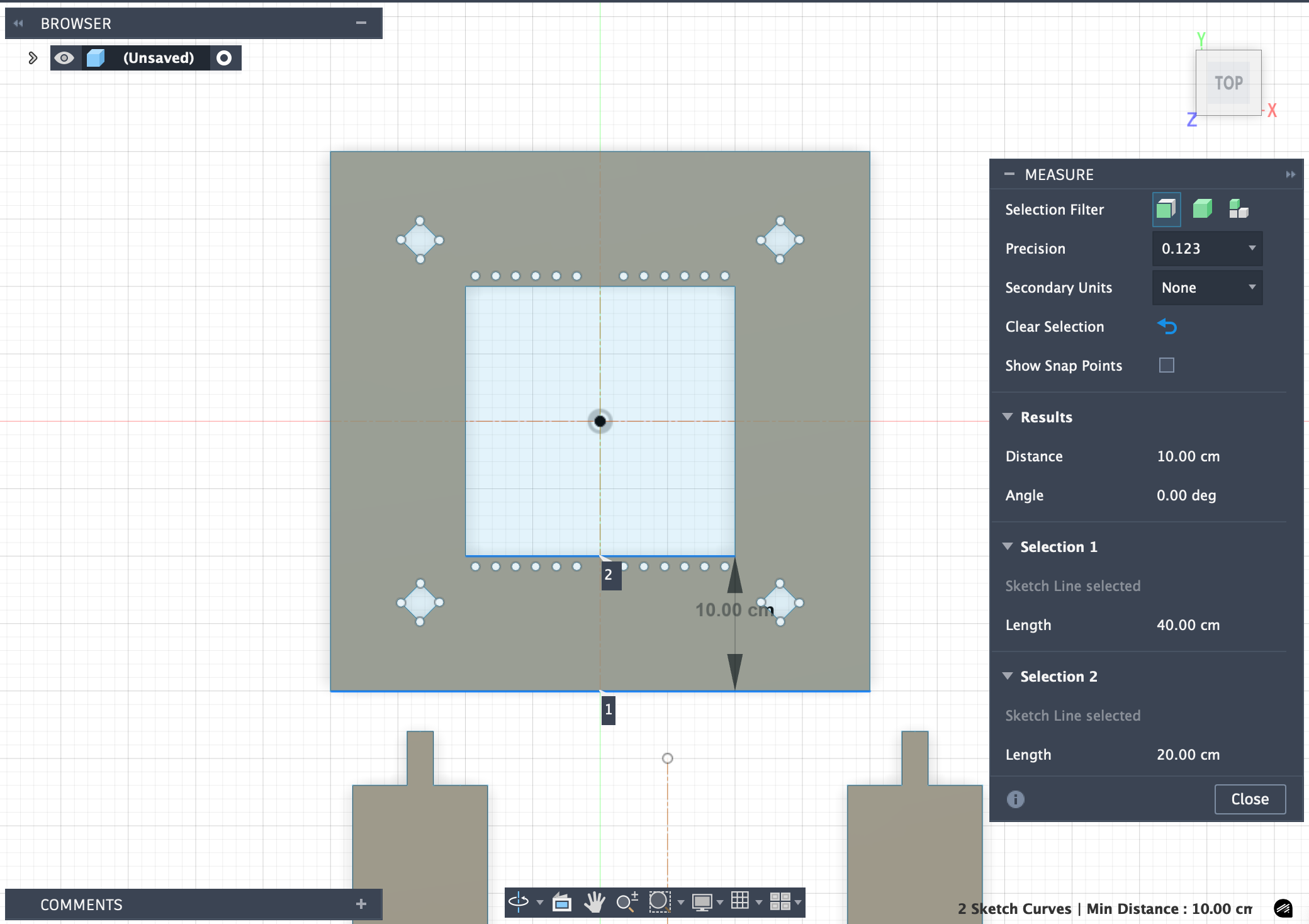
Dimension check
Before exporting the parts for machining, I checked the dimensions carefully to make sure the proportions and joint areas were correct. With the inspect tool:
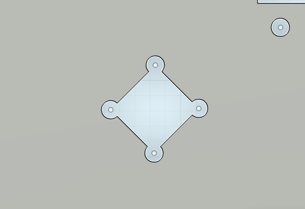
Dogbone consideration
Because CNC end mills are round, inner corners cannot be perfectly sharp. To make the press-fit joints assemble properly, I considered dogbone fillets in the slot corners. These relief cuts allow rectangular tabs to fit into milled internal corners more easily and make assembly much cleaner.
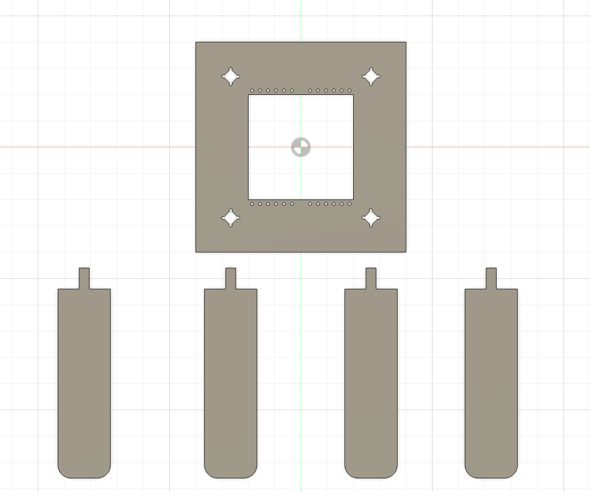
Flat layout for CNC cutting
After modeling the parts, I arranged them as a flat 2D layout for machining. This step made it easier to prepare the CAM workflow and place the parts efficiently on the plywood sheet.
The layout included:
- the square tabletop
- four leg pieces
- the joint geometry for assembly
CAM Workflow in VCarve
Importing the geometry
After preparing the 2D layout, I imported the geometry into VCarve Pro and set up the machining job.
In VCarve, I checked:
- material size
- datum position
- tool selection
- toolpath type
- cut depth
- final simulation before export
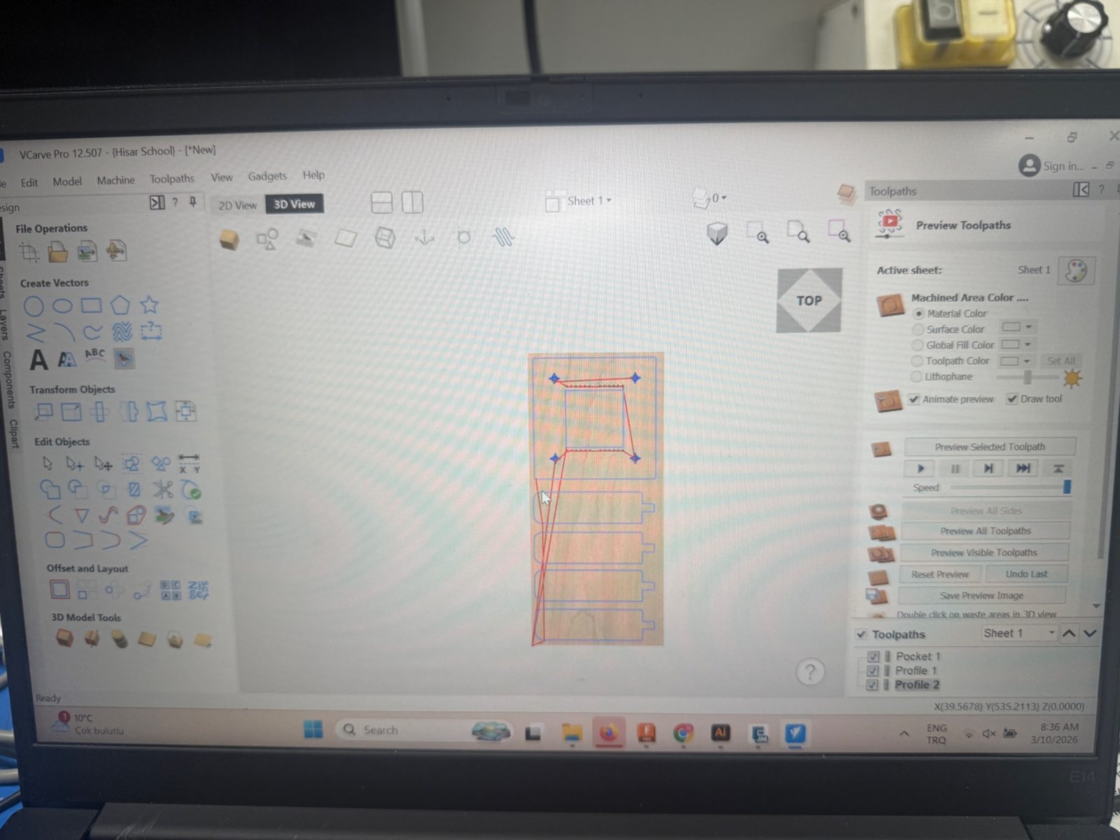
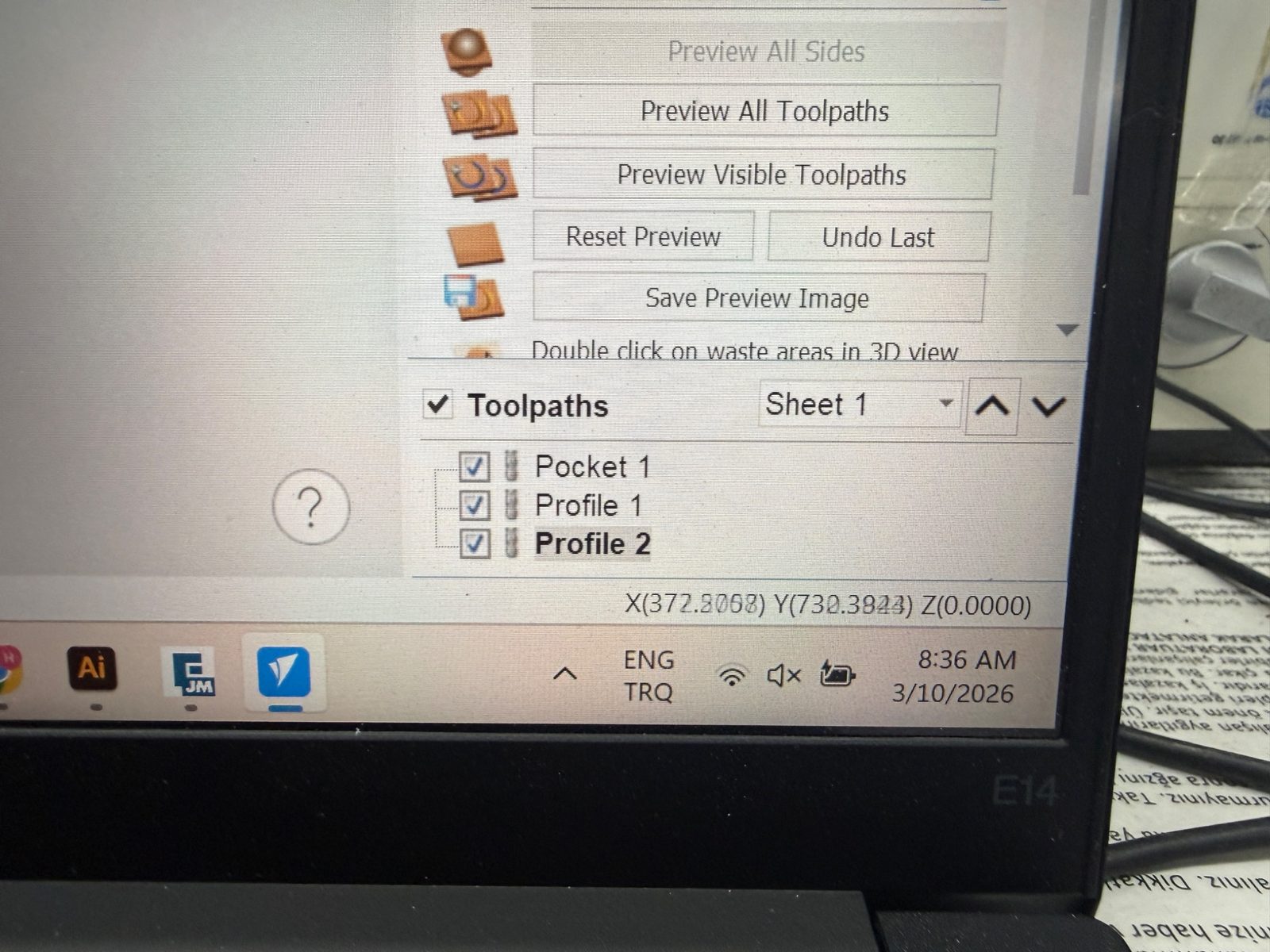
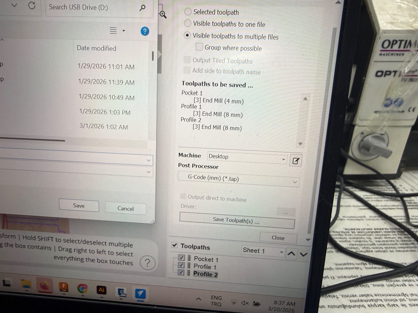
Toolpaths
I separated the machining process into multiple toolpaths. In my file, the operations included:
- Pocket 1
- Profile 1
- Profile 2
This made it easier to control which features would be cut first and how the outer profiles would be machined.
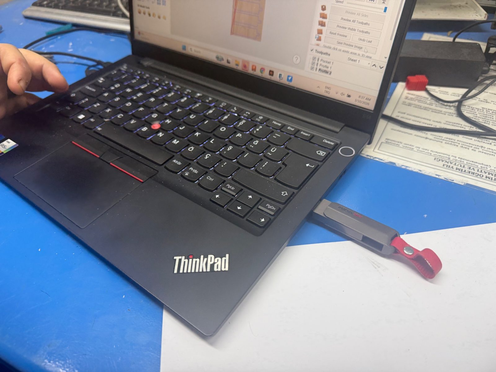
CAM workstation and export
After reviewing the preview and confirming that the visible toolpaths were correct, I exported the machining files from VCarve.
CAM settings
Main settings:
- material thickness: *2 cm *
- tool diameter: 6mm
- spindle speed: 120000 rpm
- pass depth: 6mm
- cut depth: 20.1mm
These settings are important because they directly affect the machining quality, tool load, and fit of the final assembled parts.
Machine Setup
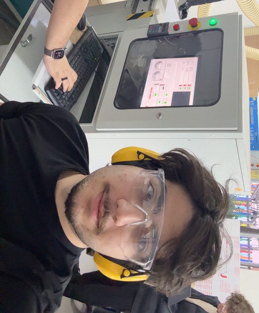
Safety reflection
Before starting the CNC process, I reviewed the lab safety rules and reflected on what is important when using a large machine like this.
The most important points for me were:
- always secure the sheet properly before cutting
- make sure the correct tool and collet are installed
- check the machine zero carefully before running the job
- wear safety glasses and hearing protection
- keep a safe distance while the machine is operating
- never leave the CNC unattended during cutting
- clean the bed before use so the material sits flat
This week reminded me that safety is part of the workflow, not a separate step. Correct setup protects both the user and the machine.
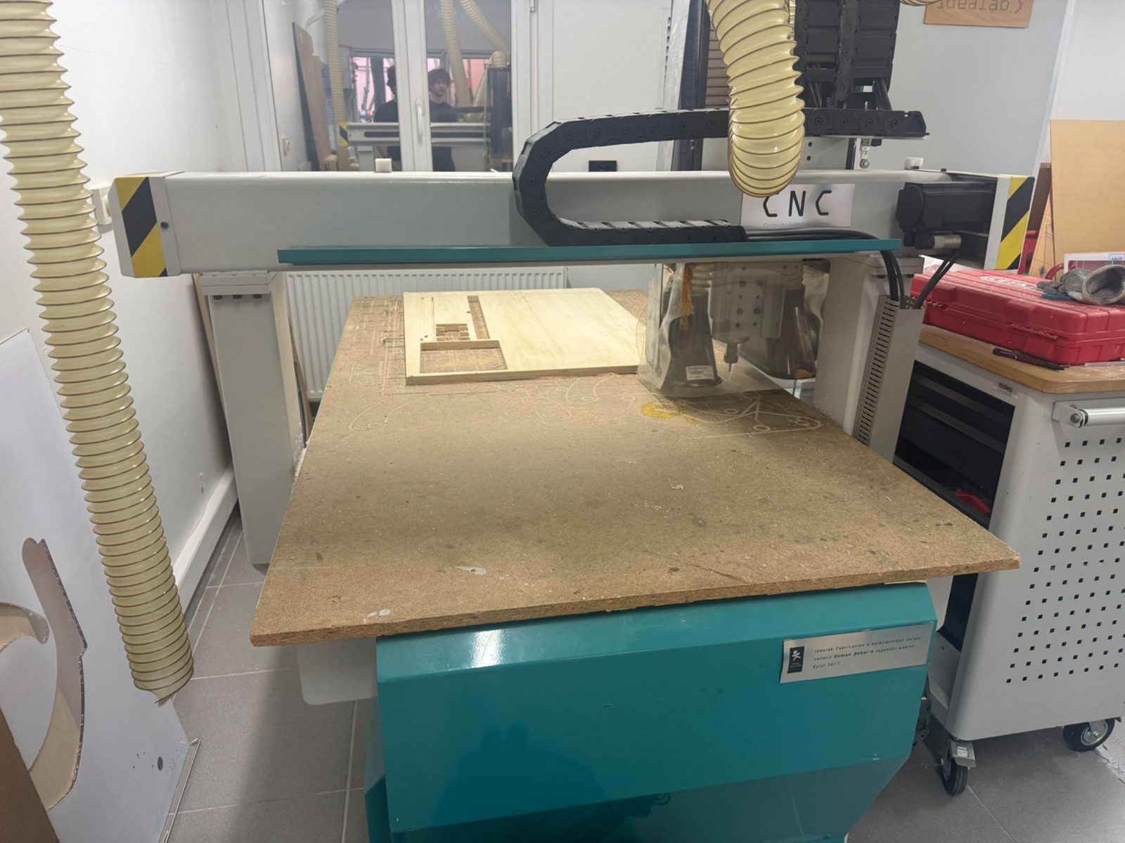
Preparing the machine bed
Before machining, I cleaned the CNC bed and checked the work area. A clean and flat setup is important for both accuracy and safety.
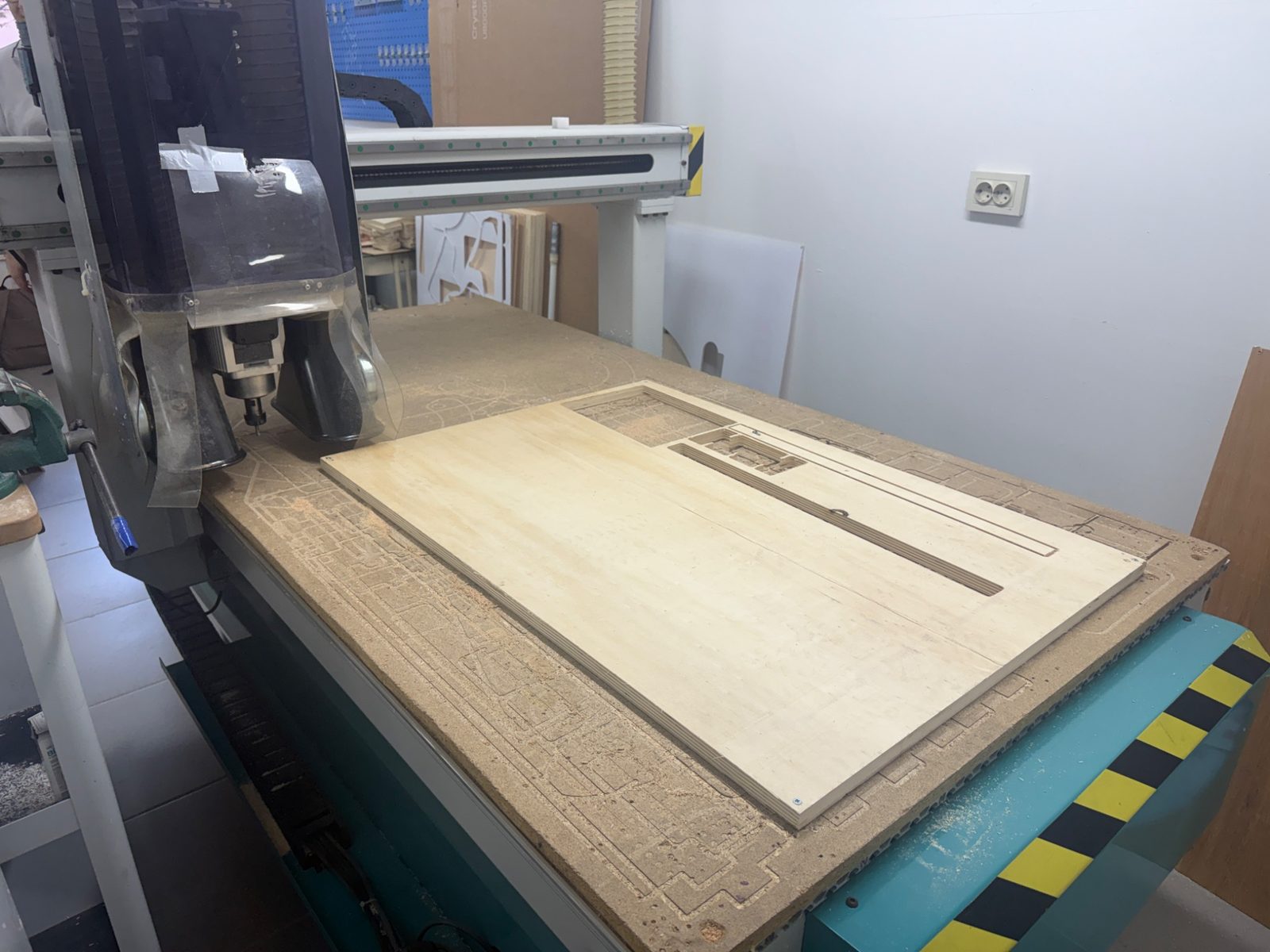
Fixing the material
The plywood sheet was fixed to the machine bed so it would not move during machining. Proper fixturing is one of the most important parts of CNC preparation because even a small movement can ruin the part.
Tool and collet selection
I checked the collets and tool holders before machining and made sure the setup matched the tool I planned to use.
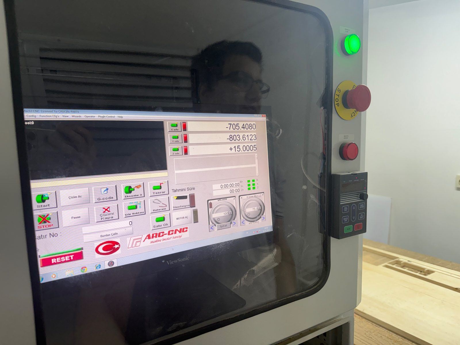
Setting the origin
After fixing the sheet, I set the X, Y, and Z origin positions for the machine before starting the cut.
Machining Process
Running the CNC job
After the setup was complete, I ran the machining process. The machine followed the prepared toolpaths in sequence, starting with the internal features and continuing with the profile cuts.
During machining, I monitored:
- whether the tool followed the expected path
- whether the sheet remained fixed
- whether the cut depth looked correct
- whether there was any unusual vibration or movement
Here is a video of the machining process:
Problems and Fixes
Fit issues and machining constraints
One of the most important things I learned this week was that a digital design does not automatically become a perfect physical object. Material thickness, machining tolerances, and tool geometry all affect the final fit.
Important constraints I had to consider:
- CNC bits are round, so they cannot create perfectly sharp inside corners
- joints must account for real material thickness
- if the fit is too tight, assembly becomes difficult
- if the fit is too loose, the structure becomes unstable
Assembly
Assembling the table
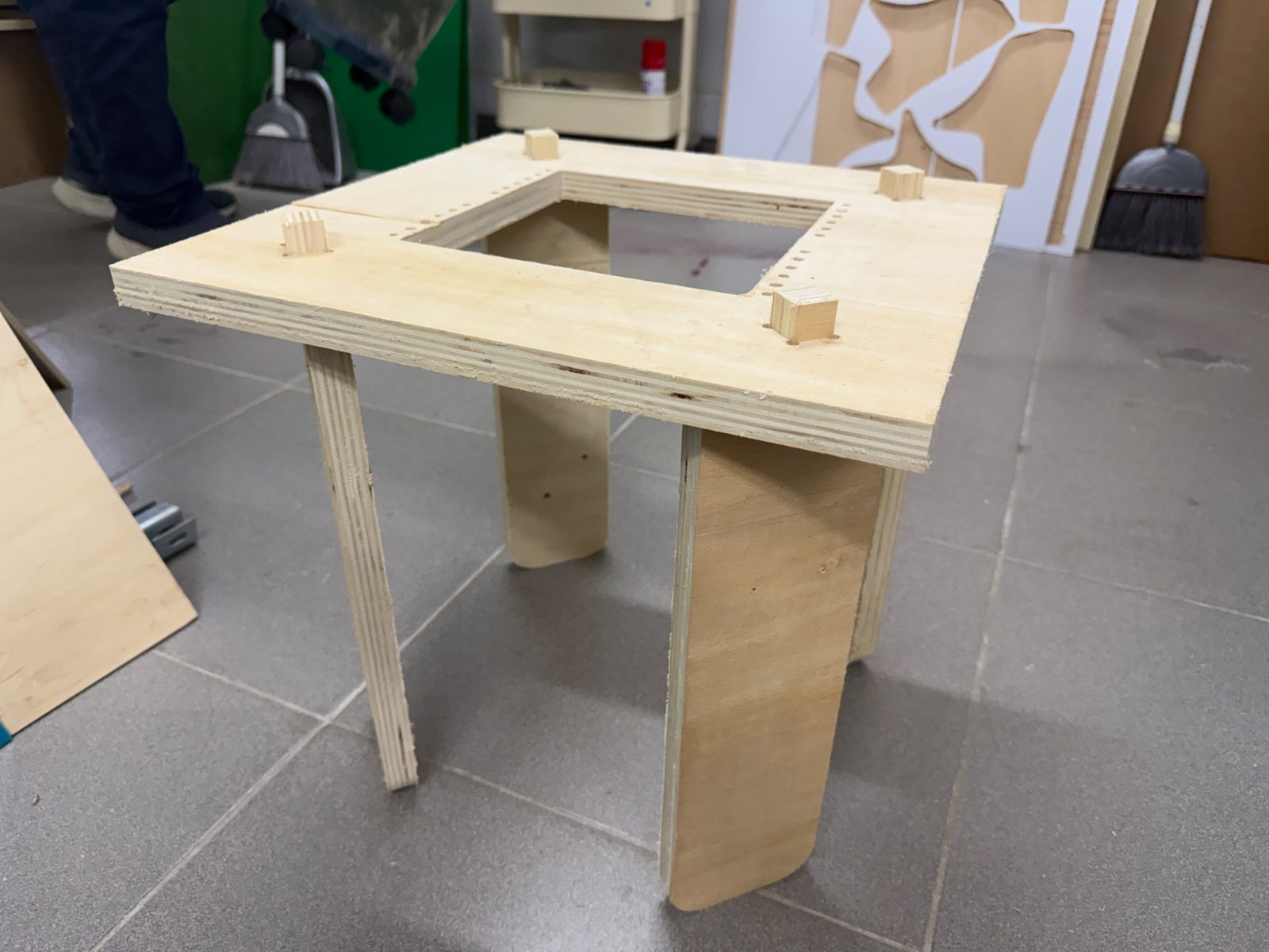
After removing the machined parts, I assembled the table by inserting the leg tabs into the matching slots on the tabletop.
The structure was designed as a press-fit assembly, so the final product did not rely on screws or glue in the assembled form.
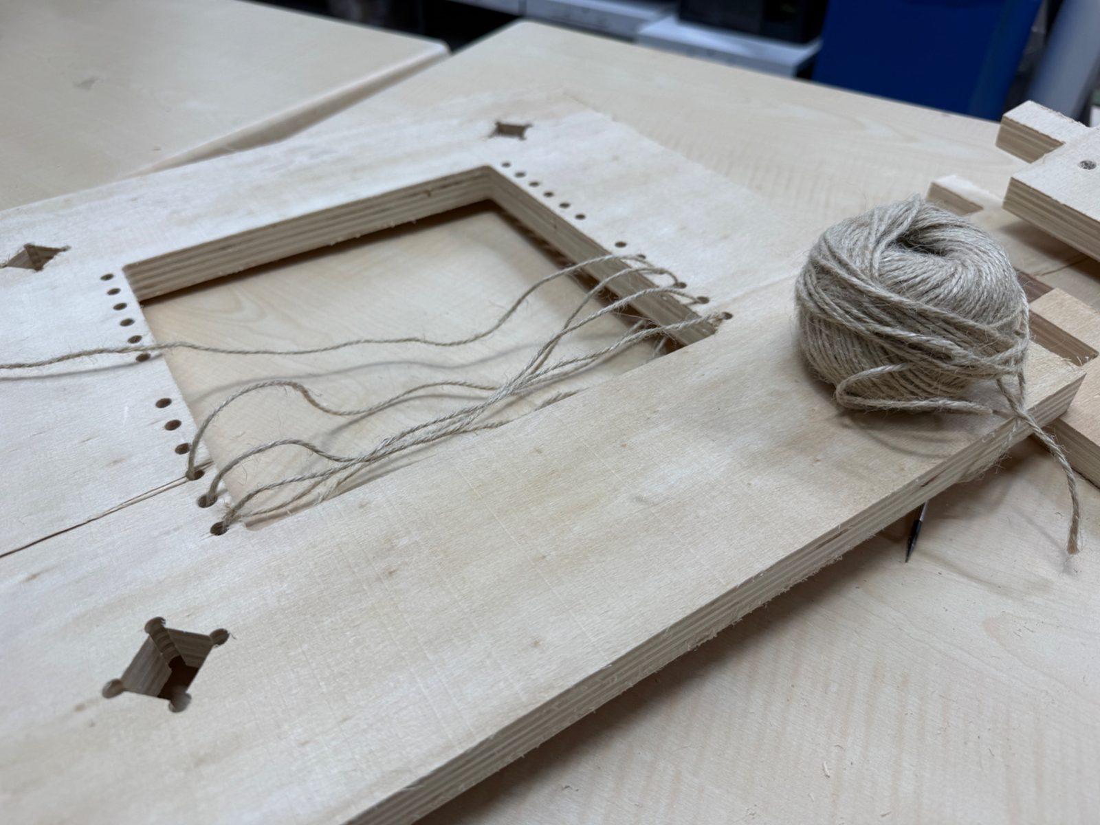
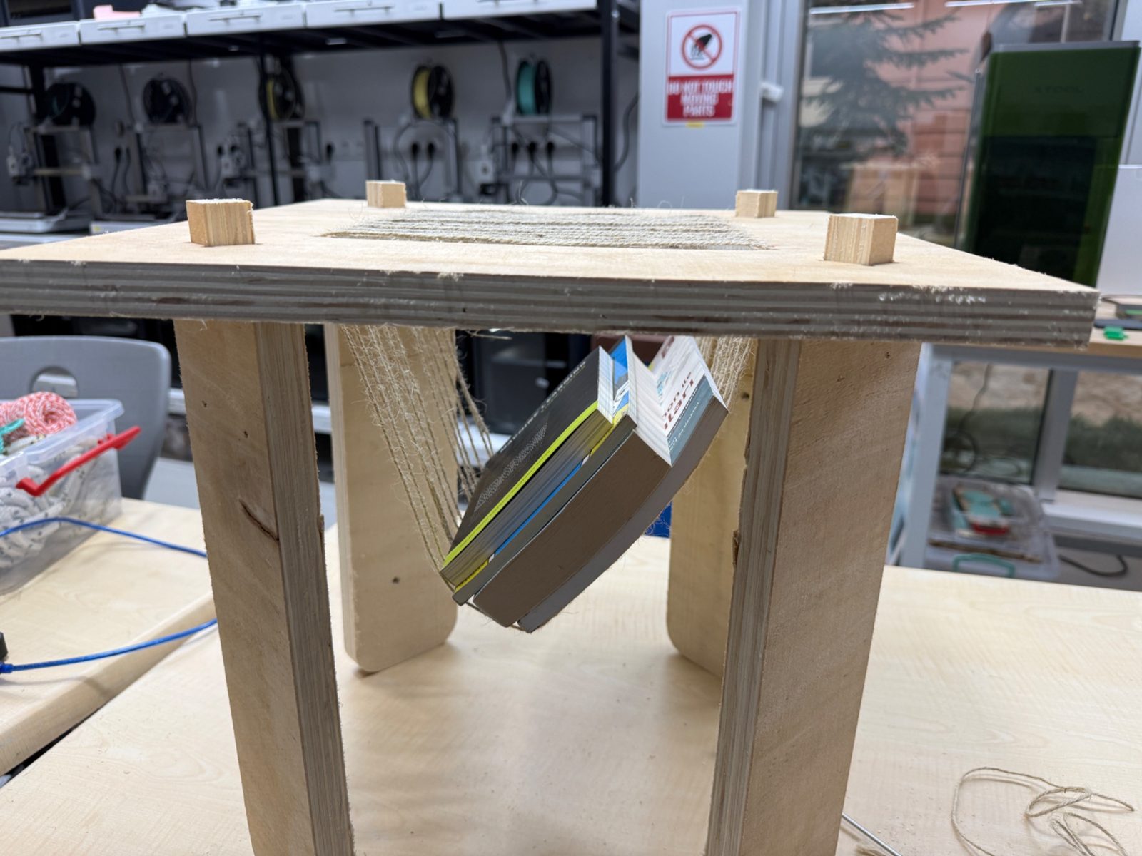
Creating the woven center
After assembling the wooden structure, I added the woven mesh in the middle section using rope. This transformed the center opening into a functional support area for books and magazines.
Using the Leftover Material
Checkerboard from the inner cutout
One part that I especially liked in this project was using the leftover square piece from the center opening instead of wasting it.
I laser cut and engraved a checkerboard from that leftover part, which turned the removed material into another usable object. This made the project more efficient and gave a second life to what would otherwise have been scrap.
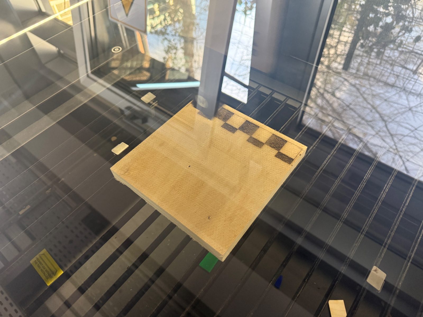
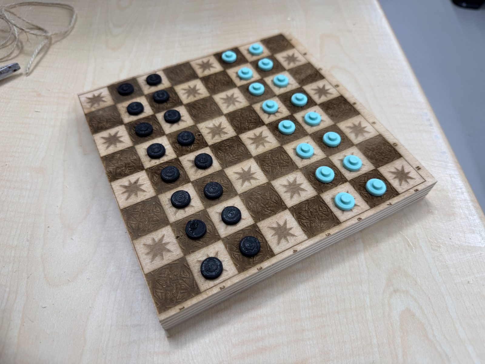
This part was not required for the assignment itself, but it was a nice extension of the project and showed how leftover material can still be used creatively.
Final Result
The final result is a compact plywood table with:
- a usable top surface
- four interlocking legs
- a woven center section
- a built-in book or magazine holder function
The woven center gives the table its main character and makes it more than a standard side table.
Reflection
This assignment helped me understand the full workflow of large format CNC fabrication from design to assembly.
The most valuable part for me was seeing how small digital decisions directly affect the physical outcome. Dimensions, tolerances, dogbone details, toolpath strategy, and machine setup all have visible consequences in the final object.
Overall, this week improved my understanding of:
- parametric design for fabrication
- CNC machining constraints
- CAM workflow in VCarve
- safe machine operation
- press-fit assembly logic
- making better use of leftover material