Introduction
This week focused on input devices and how to interface sensors with a microcontroller board.
For this assignment, I used a new modular board based on the Seeed XIAO ESP32 that I designed. Instead of preparing a separate board for every sensor, I designed one reusable board that could support different input devices through jumper-wire connections.
For Week 09, I tested four different input devices:
- MAX4466 microphone module
- MPU-6050
- button
- TTP223B touch sensor
Group Assignment
Group assignment page:
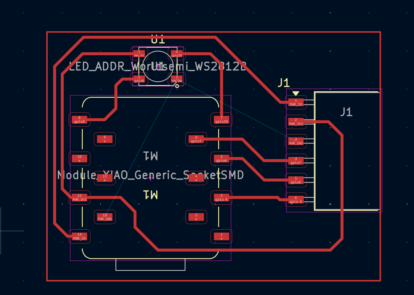
Board Overview
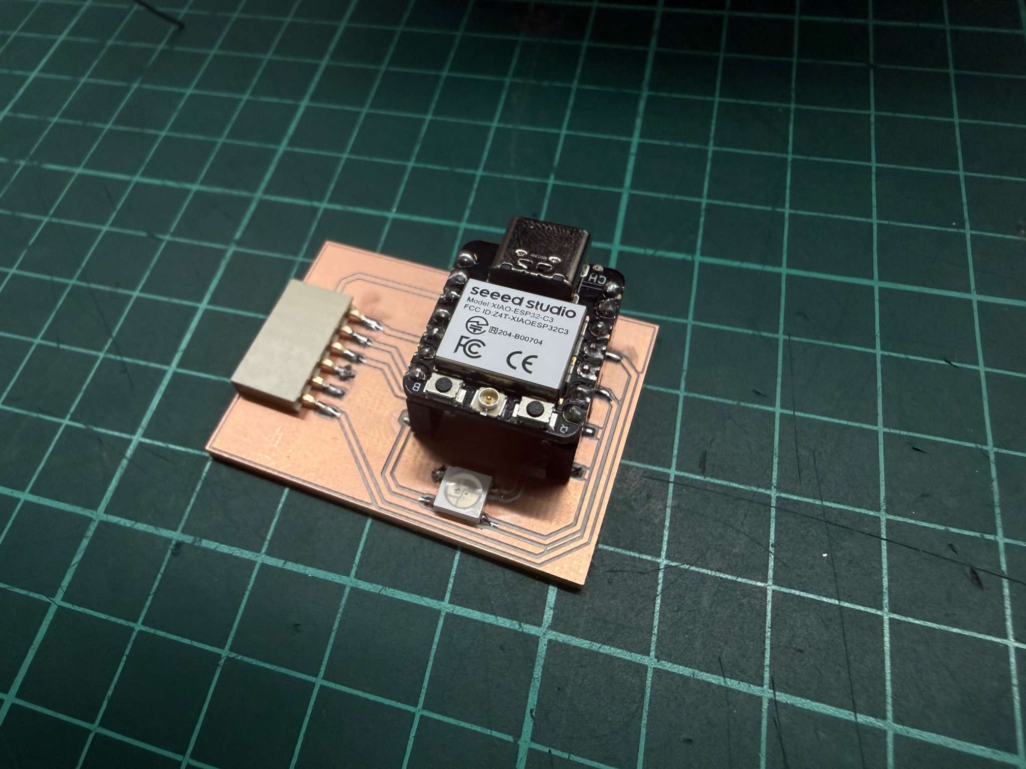
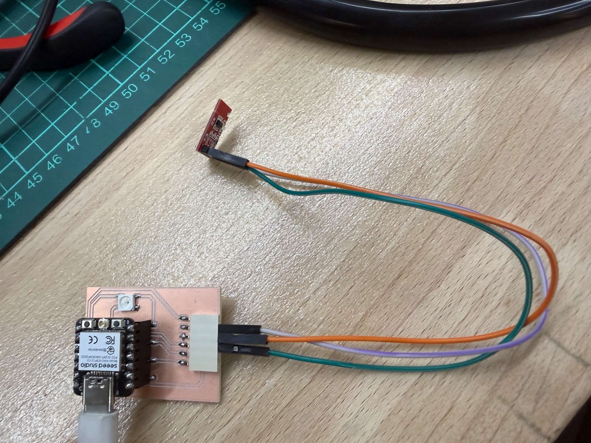
Modular XIAO ESP32 board
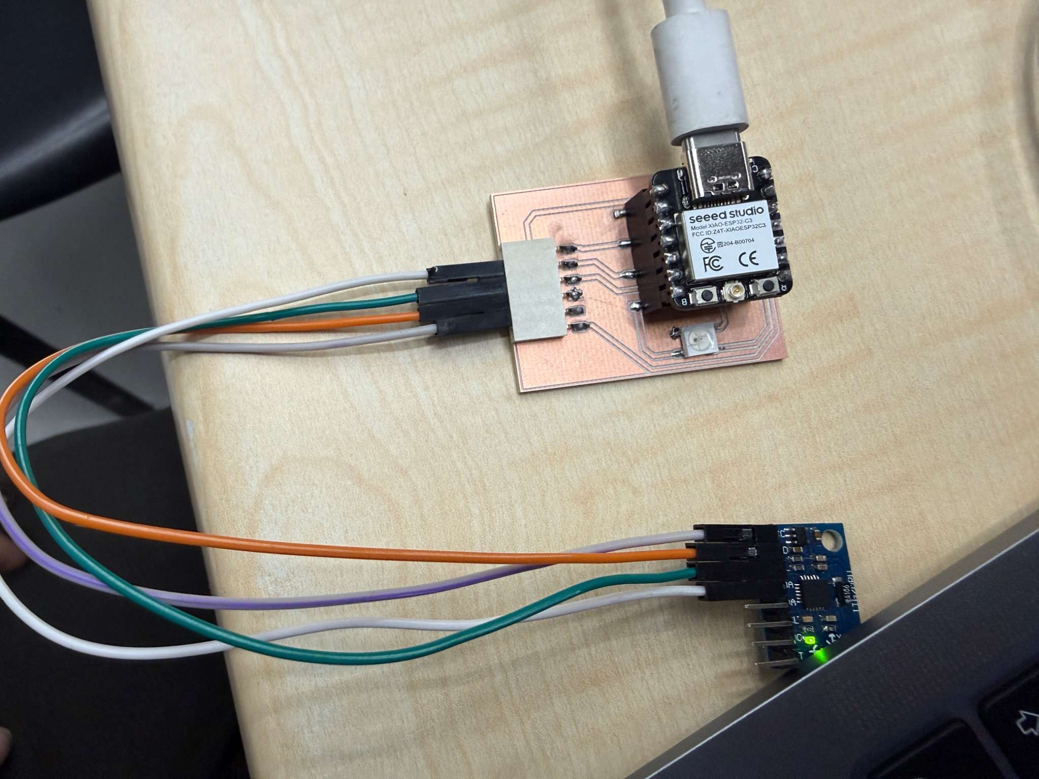
For this week, I used a new modular board built around the Seeed XIAO ESP32 C3. The main goal of this board was to make sensor testing easier, faster, and more reusable.
Instead of designing a board for a single sensor, I added a 6-pin horizontal socket so that different sensor modules could be connected using jumper wires. This made the board much more flexible and suitable for both analog and communication-based sensors.
Why I designed it this way
I wanted the same board to support different kinds of sensors, so I exposed several useful connections on the socket:
- GND
- 3.3V
- 5V
- GPIO pins
- one analog-capable input
- I2C-ready connections for future and current digital sensors
This design allowed me to test analog sensors like the microphone, digital input devices like the button and touch sensor, and communication-based sensors like the MPU-6050, all on the same board.
Notes about the board
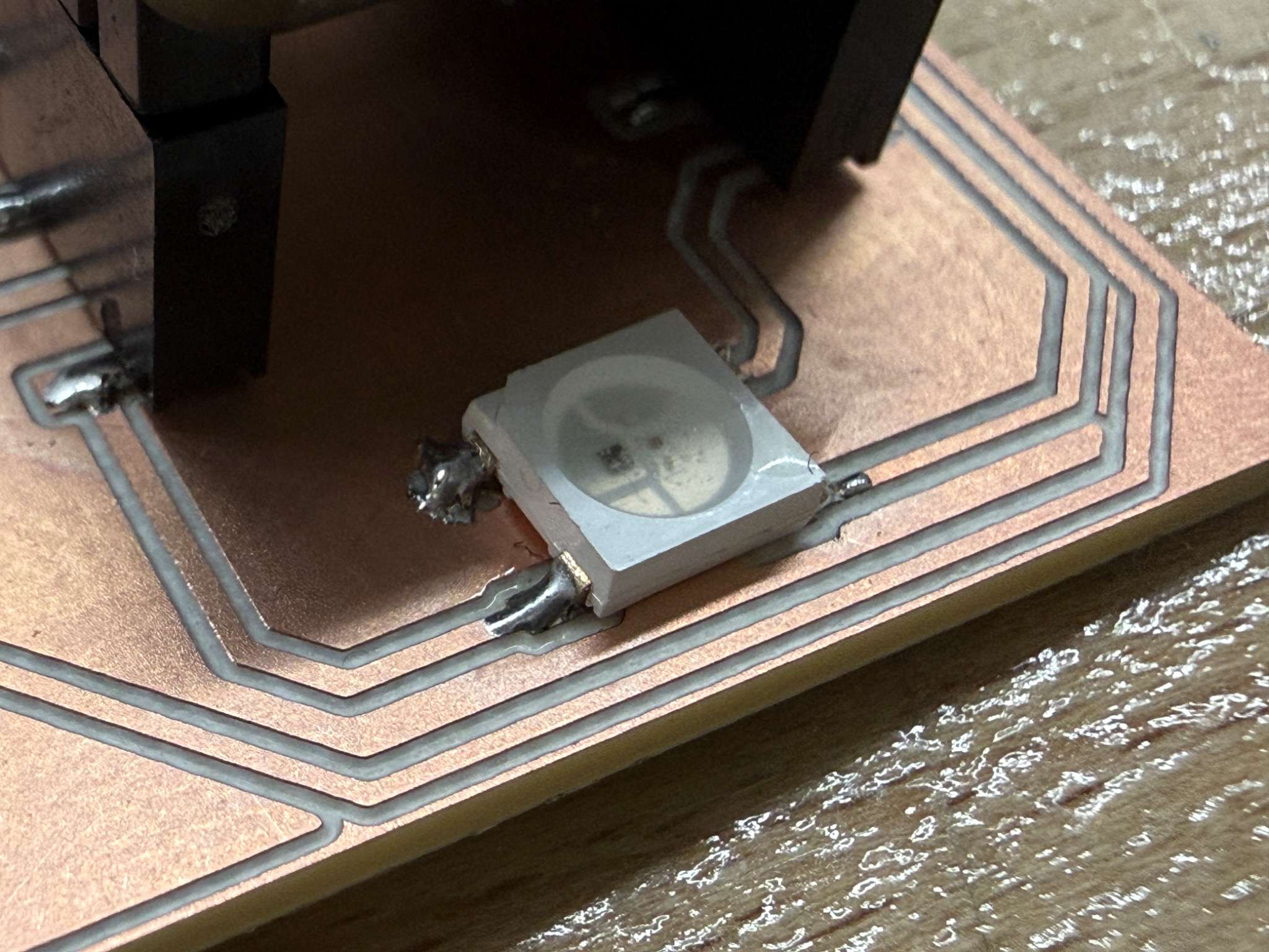
I also added an RGB LED to the board, but that was not the main focus of this week. For Week 09, the important part of the board was its modular sensor interface and how it allowed me to compare different kinds of inputs using the same microcontroller platform.
Input Device 1 - Microphone
Sensor overview
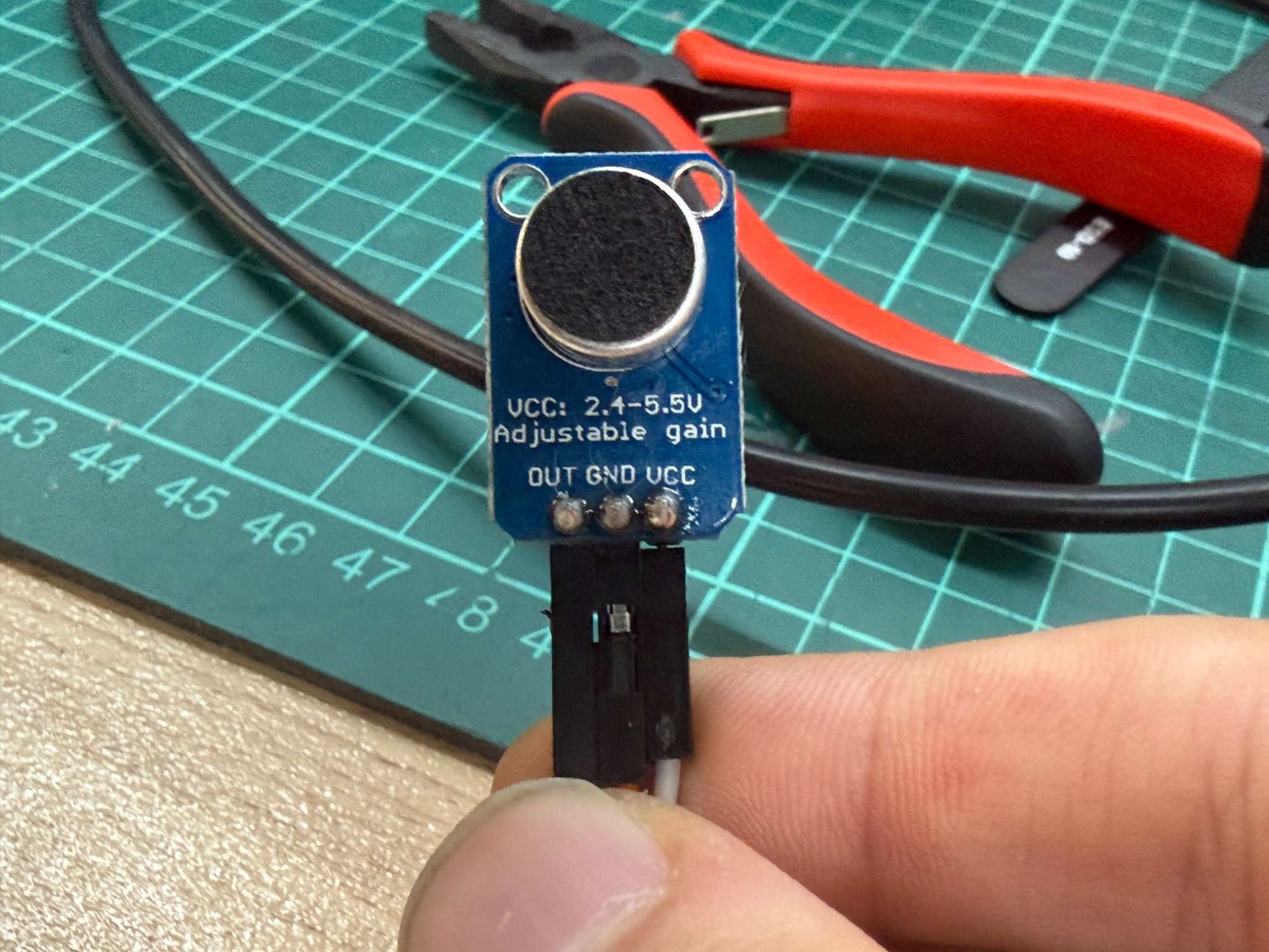
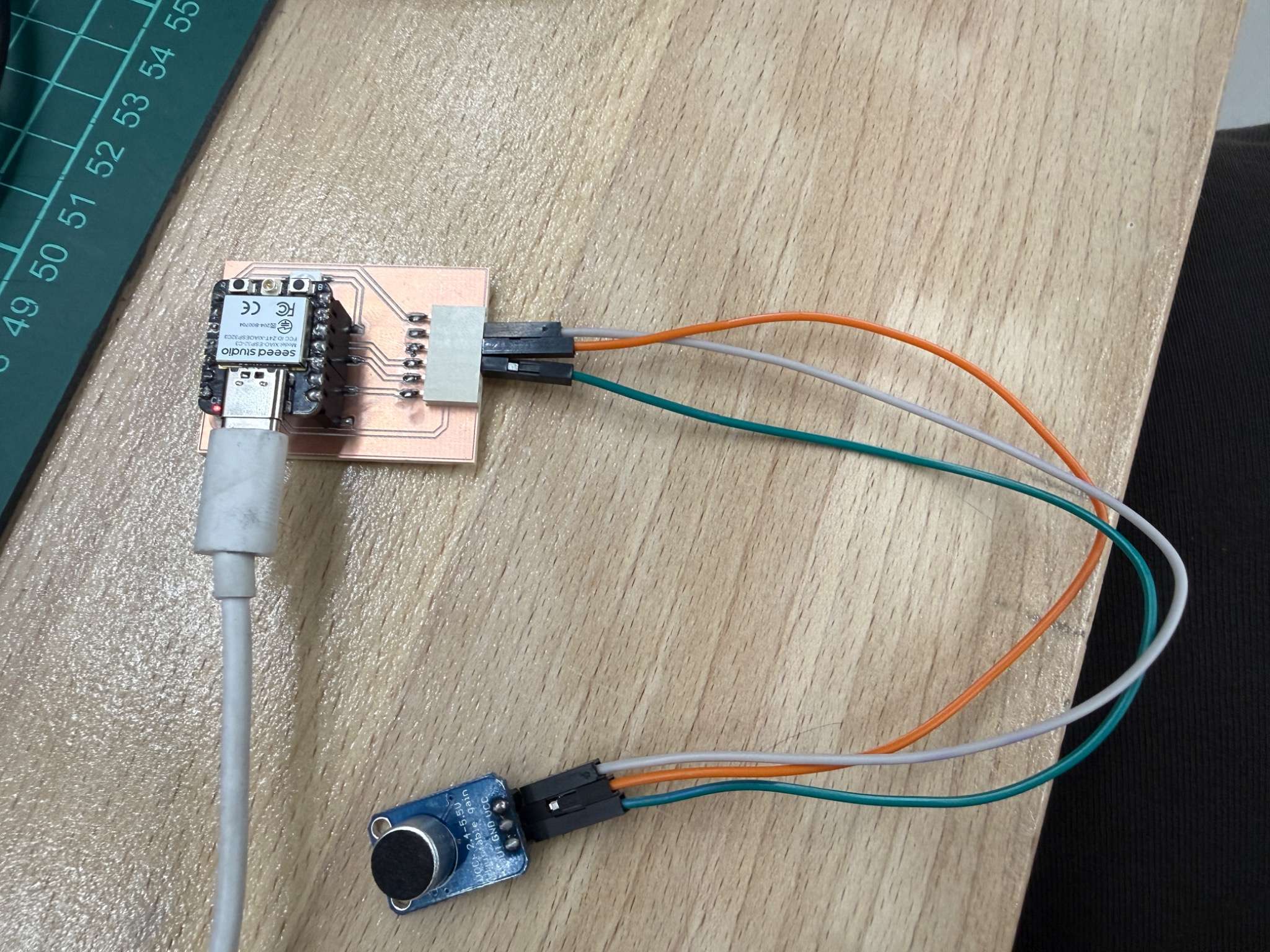
For sound input, I used a MAX4466-based microphone module.
The MAX4466 is a microphone preamplifier designed for low-power microphone applications. According to the datasheet, it operates from 2.4 V to 5.5 V, and has rail-to-rail output, which makes it suitable for analog measurement with a microcontroller ADC.
Why I chose it
This sensor fit my modular board very well because it only needed:
- power
- ground
- one analog input pin
That made it a good example of an analog input device.
How it works
The microphone module does not directly output a value like “sound level in decibels.” Instead, it outputs an analog voltage signal that changes according to the sound waveform. The MAX4466 stage amplifies the microphone signal so that the ESP32 can read it more easily through its ADC.
In practice, this means:
- louder sound causes larger signal variation
- the ESP32 reads that variation as changing analog values
- the code can interpret raw waveform, peaks, or average level
Code
const int MIC_PIN = 4;

void setup() {
  Serial.begin(115200);
}

void loop() {
  int value = analogRead(MIC_PIN);
  Serial.println(value);
  delay(20);
}
Video
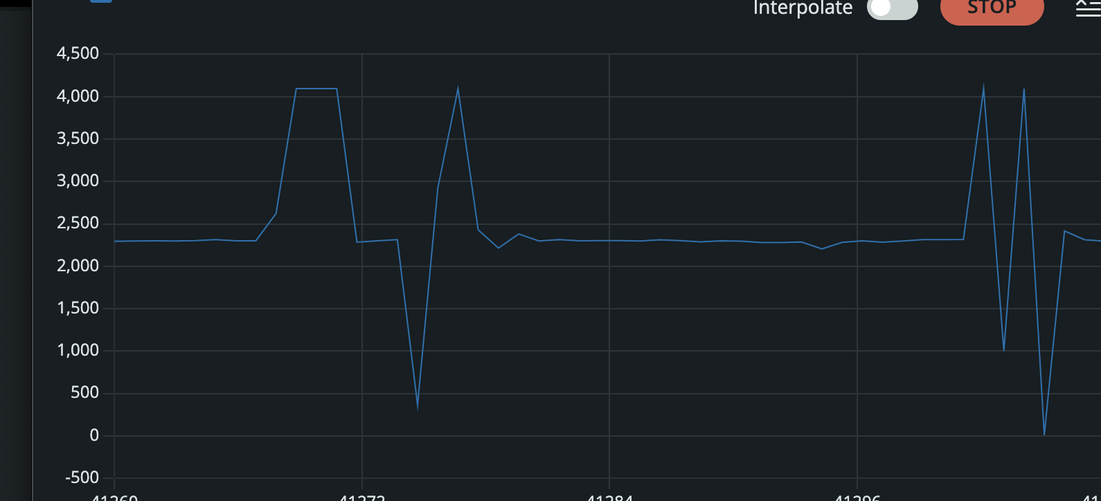
I used the Serial Monitor to observe how the ADC values changed when I spoke near the microphone or created sound around it.
What I learned
This sensor showed me that analog input is very different from a simple on/off input. The values are always changing, so interpreting the signal is part of the work. It also showed me that analog input can be noisy and needs more interpretation than a digital sensor.
Input Device 2 - MPU-6050
Sensor overview
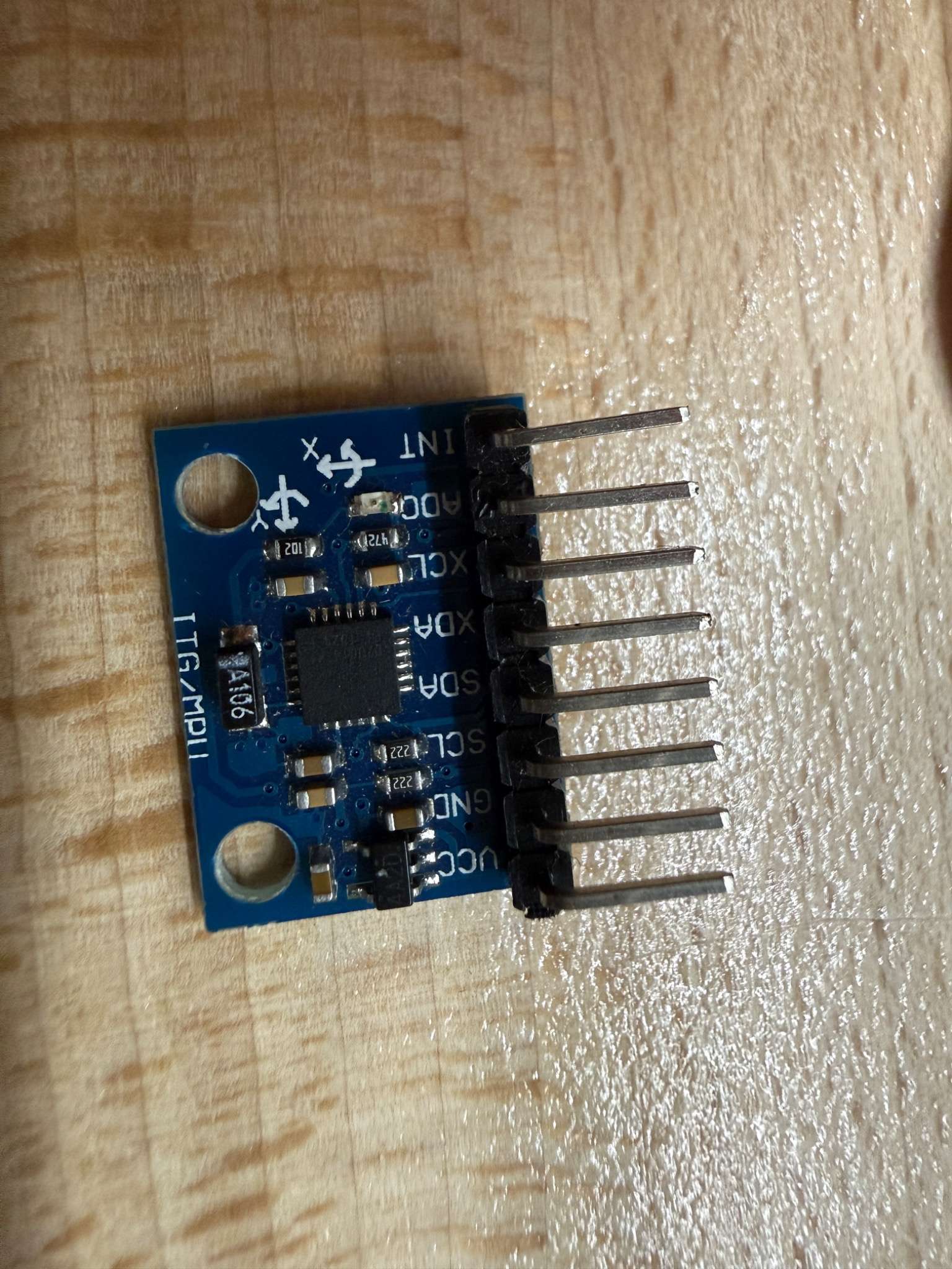
For motion sensing, I used the MPU-6050.
The MPU-6050 combines a 3-axis gyroscope and a 3-axis accelerometer in one device, making it a 6-axis motion sensor. It communicates through I2C, which makes it a good test for communication-based input rather than direct analog reading.
Why I chose it
I wanted this board to support more than just analog sensors. The MPU-6050 was a good test because it uses:
- power
- ground
- SDA
- SCL
That matched the I2C-ready part of my modular header design and proved that the same board could support more advanced digital sensors as well.
How it works
This sensor measures:
- rotational motion through the gyroscope
So instead of reading a simple analog voltage, the microcontroller communicates with the module and receives structured motion data. The physical relationship is straightforward:
- when the sensor is tilted, rotated, or moved
- the measured gyro values change
Code
#include <Wire.h>
#include <Adafruit_MPU6050.h>
#include <Adafruit_Sensor.h>

Adafruit_MPU6050 mpu;

void setup() {
  Serial.begin(115200);
  Wire.begin(6, 7);

  if (!mpu.begin()) {
    Serial.println("MPU6050 not found");
    while (1);
  }
}

void loop() {
  sensors_event_t a, g, temp;
  mpu.getEvent(&a, &g, &temp);

  Serial.print(a.acceleration.x); Serial.print(", ");
  Serial.print(a.acceleration.y); Serial.print(", ");
  Serial.println(a.acceleration.z);

  delay(200);
}
Video
What I learned
Communication-based sensors require correct wiring, correct initialization, and correct reading of multiple outputs. It also showed why designing the board with I2C support was useful from the start.
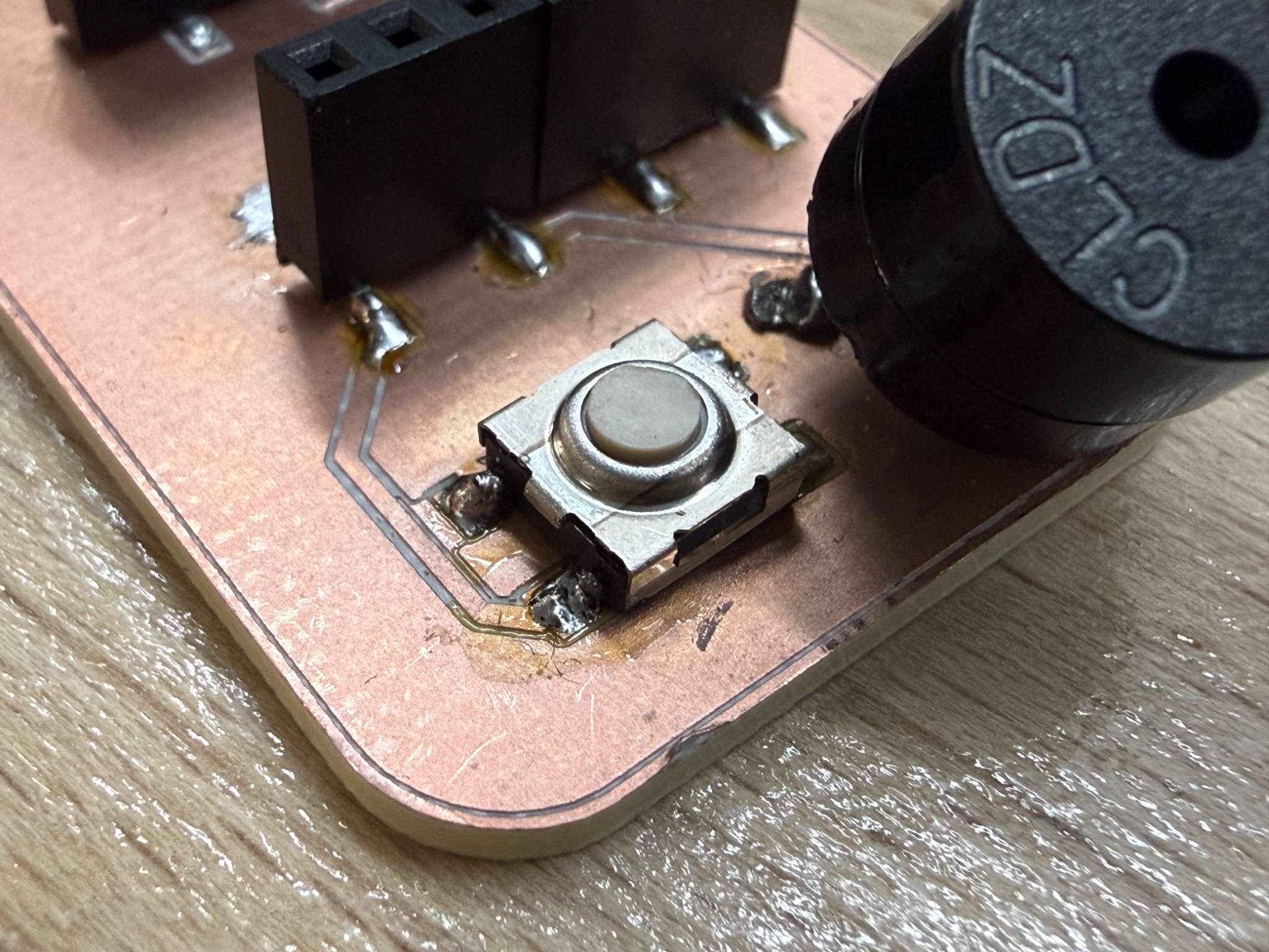
Input Device 3 - Button
Sensor overview
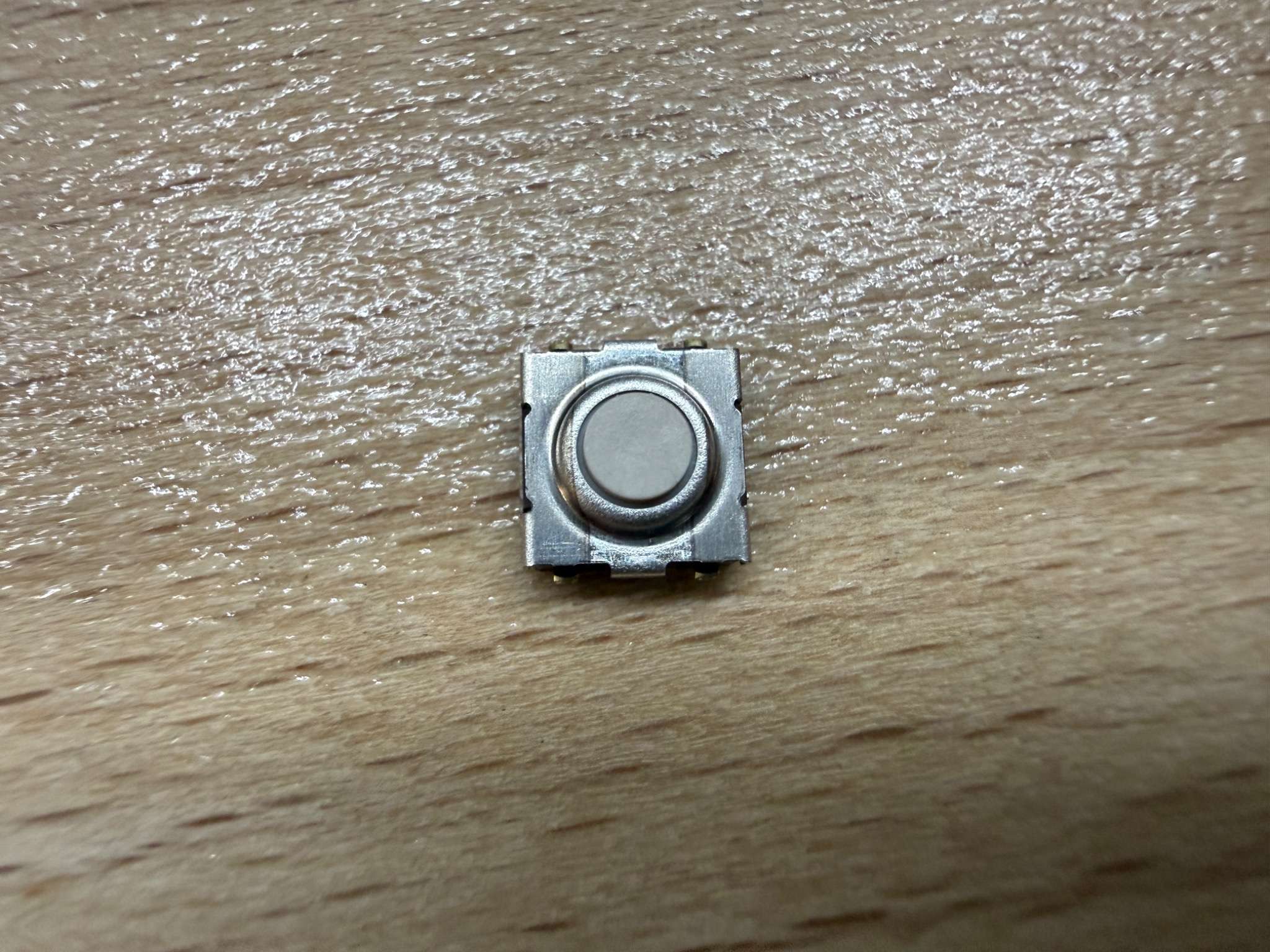
The button is the simplest input device I used this week, but it is still important because it is the clearest example of a digital input. I used my week8 board to test how a button works without wasting any materials since it already consists of a button (Omron Tacile Switch).
Unlike the microphone or motion sensor, the button only has two states:
- pressed
- not pressed
Why I included it
I included the button because it provided a clear comparison with the other sensors:
- button = simple digital input
- microphone = analog input
- MPU-6050 = I2C communication-based input sensor
- touch sensor = digital capacitive input
Code
const int BUTTON_PIN = 7;

void setup() {
  Serial.begin(115200);
  pinMode(BUTTON_PIN, INPUT_PULLUP);
}

void loop() {
  Serial.println(digitalRead(BUTTON_PIN));
  delay(100);
}
Test result
I used the Serial Monitor to confirm that the value changed when the button was pressed and released.
What I learned
The button was useful because it gave me a reliable baseline input. It also helped confirm that the board and GPIO logic were working.
Input Device 4 - TTP223B Touch Sensor
Sensor overview
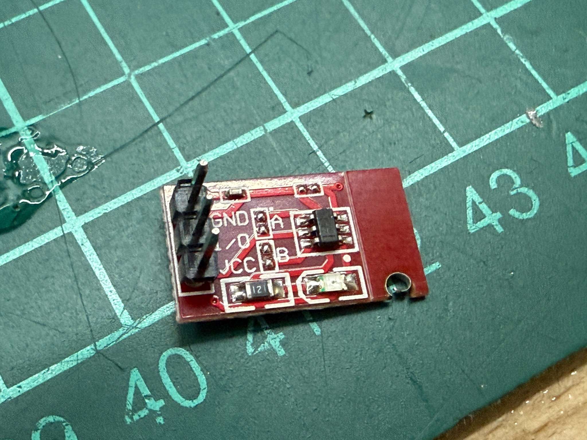
For a fourth sensor, I used a TTP223B touch sensor module.
The TTP223 family is a one-key capacitive touch detector designed to replace a traditional button. It is suitable as a digital input for a microcontroller and behaves like a touch-based switch.
Why I chose it
This sensor was interesting because it behaves like a button from the user perspective, but internally it works through capacitive touch detection rather than mechanical contact.
The module I used already came as a separate small board, so I did not need to fabricate the sensing part myself. Since it is a breakout-style module, it only needed a small number of connections and could easily be tested using jumper wires.
How it works
The sensor detects touch through capacitance change rather than physical switch movement. In practice, this means:
- touching the sensor pad changes the internal detection state
- the module outputs a digital signal
- the ESP32 reads that signal like a digital input
So even though it can be treated in code similarly to a button, the sensing principle is different.
Code
For the touch sensor, I read the output pin as a digital input.
const int TOUCH_PIN = 4;

void setup() {
  Serial.begin(115200);
  pinMode(TOUCH_PIN, INPUT);
}

void loop() {
  Serial.println(digitalRead(TOUCH_PIN));
  delay(100);
}
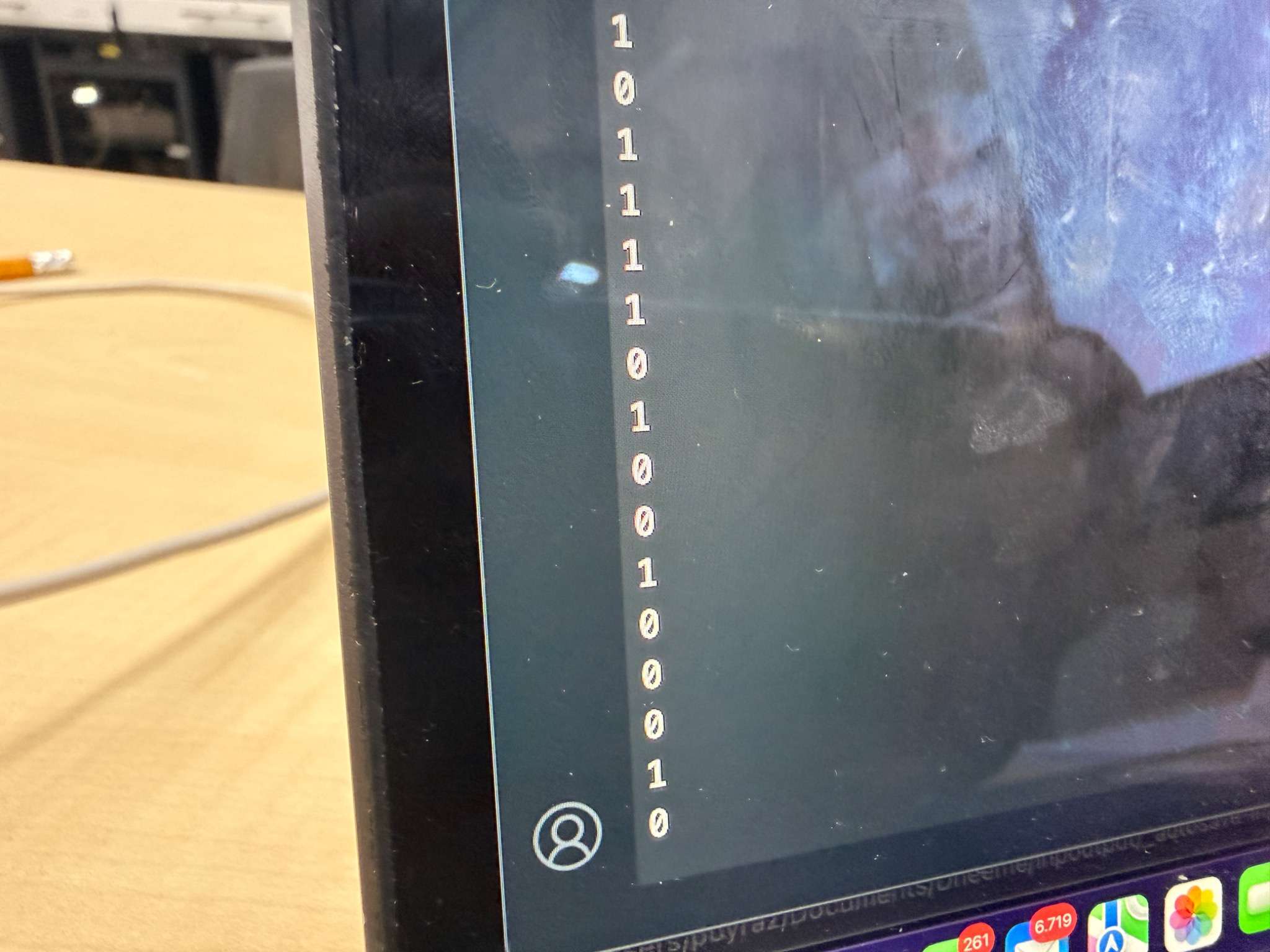
Test result
I observed the sensor output changing when I touched and released the touch surface.
Video
What I learned
The touch sensor was a nice comparison with the button. Both of them can produce a digital result, but the physical sensing mechanism is very different. This helped me understand that two sensors can look similar in code while measuring physical interaction in different ways.
Problems and Fixes
Modular wiring challenges
A modular board makes testing easier, but it also increases the chance of wiring mistakes. I had to be careful about:
- which pin was analog
- which pins were for I2C
- which modules expected 3.3V
Signal interpretation
Especially for the microphone, reading values was not enough on its own. The raw values changed constantly, so understanding what they meant required more interpretation than the button or touch sensor.
Reflection
This week helped me understand that input devices can work in very different ways even when connected to the same board. “input devices” is actually a broad category with very different workflows.
The most useful part of the assignment for me was designing and using a modular board that could support multiple sensor types. That made it much easier to compare:
- digital input
- analog input
- communication-based sensor input
The clearest takeaway for me was:
- a button gives simple digital state
- a touch sensor also gives digital state, but through capacitive sensing
- a microphone gives an analog signal
- an MPU-6050 gives structured motion data through I2C