Introduction
This week focused on output devices and how to control them with a microcontroller.
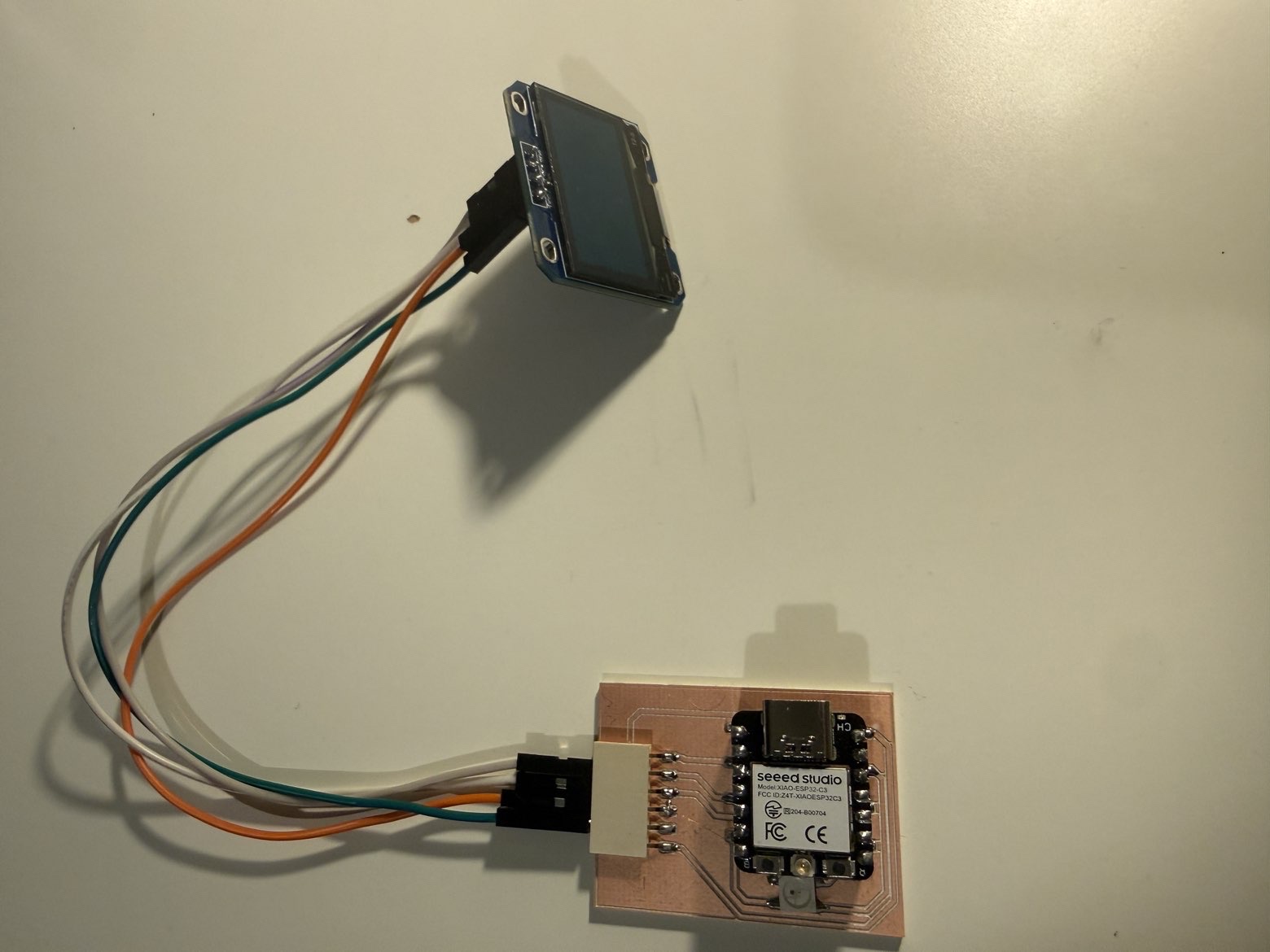
For this assignment, I reused the same modular Seeed XIAO ESP32-C3 board that I documented in Week 09, so I did not design a new board for this week. Instead, I focused on interfacing and controlling different kinds of outputs using the same platform.
For Week 10, I tested three different output devices:
- on-board WS2812B RGB LED
- SG90 servo motor
- I2C OLED display (SH110X)
Group Assignment
Group assignment page:
Board Used
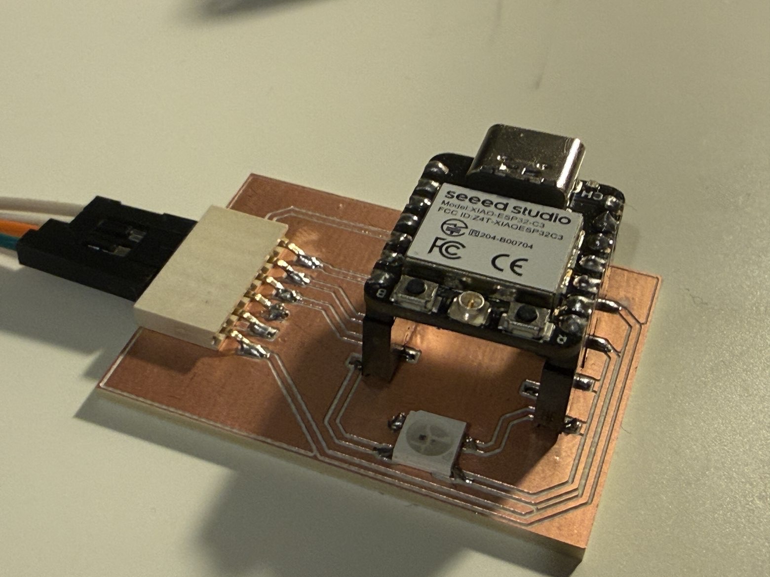
I reused the same modular XIAO ESP32-C3 board from Week 09.
Link to previous board documentation: [add your Week 09 page link here]
Since the board already included:
- an on-board WS2812B RGB LED
- exposed GPIO pins
- 5V / 3.3V / GND
- I2C-ready connections
it was already suitable for this week’s output device tests.
Output Device 1 - On-board WS2812B RGB LED
Device overview
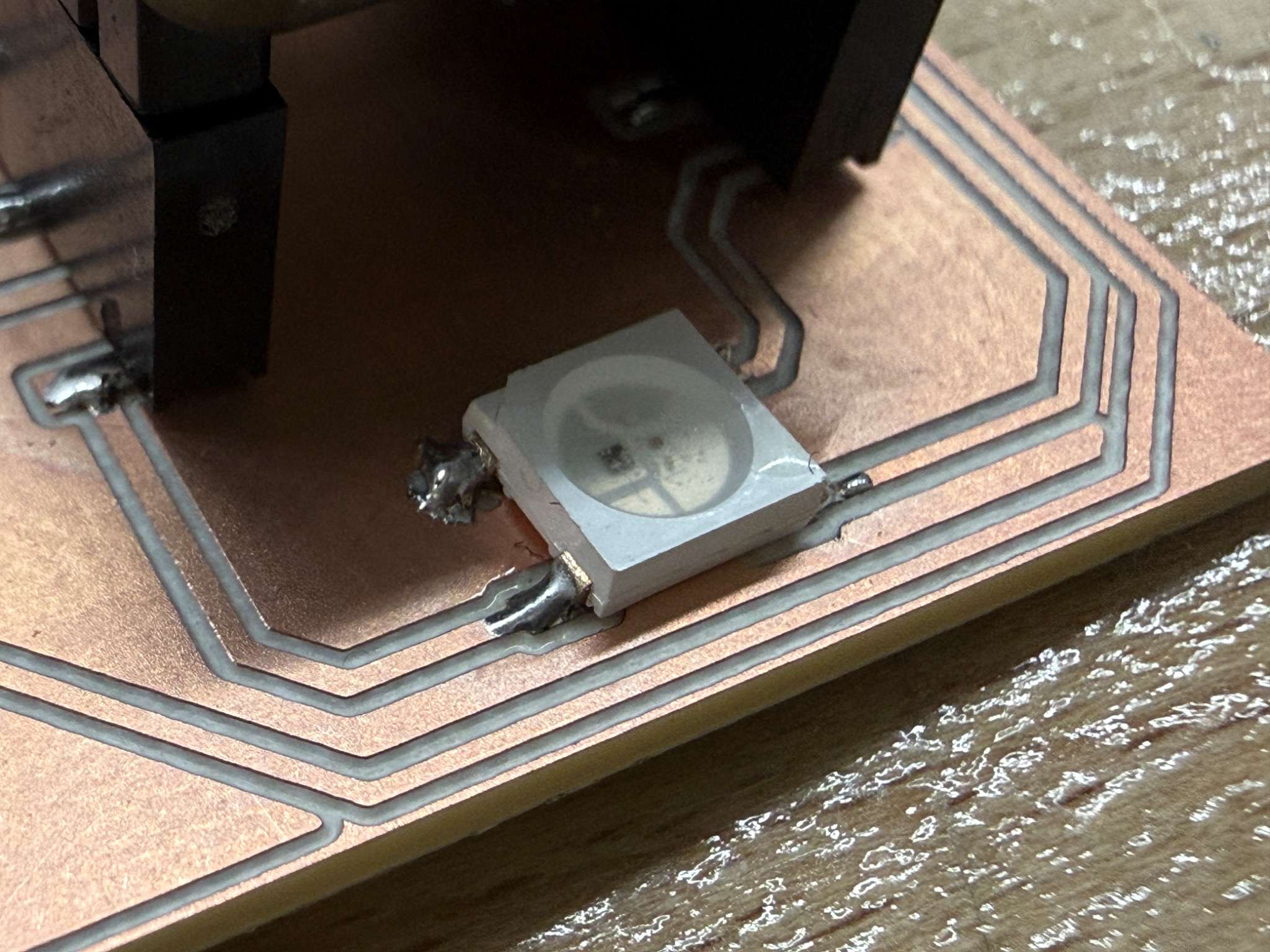
The first output device I used was the WS2812B RGB LED already placed on my board.
This was a good starting point because it is a compact but expressive output device. Even though it is only one LED, it can produce many different colors by combining red, green, and blue light.
Why I chose it
I chose the WS2812B because:
- it was already integrated into my board
- it can demonstrate programmable light output
- it allowed me to test an addressable LED directly on my custom board
How it works
On my PCB, the WS2812B footprint is connected to two GPIO-related traces. This is because the LED package includes both:
- DIN for incoming control data
- DOUT for passing data to another WS2812B in a chain
So while two signal-related traces are routed on the board, only the data input pin is actually used to control the LED in code. The other trace corresponds to the LED’s serial data output and would only be useful if another addressable LED were connected after it.
For this reason, the LED still behaves as a single-wire controlled output device from the microcontroller side.
Code
#include <Adafruit_NeoPixel.h>

#define LED_PIN   21
#define NUMPIXELS 1

Adafruit_NeoPixel pixels(NUMPIXELS, LED_PIN, NEO_GRB + NEO_KHZ800);

void setup() {
  pixels.begin();
  pixels.clear();
  pixels.show();
}

void loop() {
  pixels.setPixelColor(0, pixels.Color(255, 0, 0));
  pixels.show();
  delay(500);

  pixels.setPixelColor(0, pixels.Color(0, 255, 0));
  pixels.show();
  delay(500);

  pixels.setPixelColor(0, pixels.Color(0, 0, 255));
  pixels.show();
  delay(500);

  pixels.setPixelColor(0, pixels.Color(255, 255, 255));
  pixels.show();
  delay(500);

  pixels.clear();
  pixels.show();
  delay(500);
}
How the code works
In this code:
- the Adafruit_NeoPixel library is used to control the LED
- only one GPIO pin is used in software, because only the WS2812B data input is driven by the microcontroller
- the second routed data-related trace on the PCB is not separately controlled in code
- in the loop, the LED changes color step by step:
- red
- green
- blue
- white
- off
Result
The RGB LED responded correctly and displayed the programmed colors in sequence.
Video
What I learned
This test helped me understand the difference between a normal RGB LED and an addressable RGB LED. Even though the PCB routes both data-related pads of the WS2812B footprint, the LED is still controlled through only one incoming data line. The second data connection is there for signal chaining, not as a separate control line.
Output Device 2 - SG90 Servo Motor
Device overview
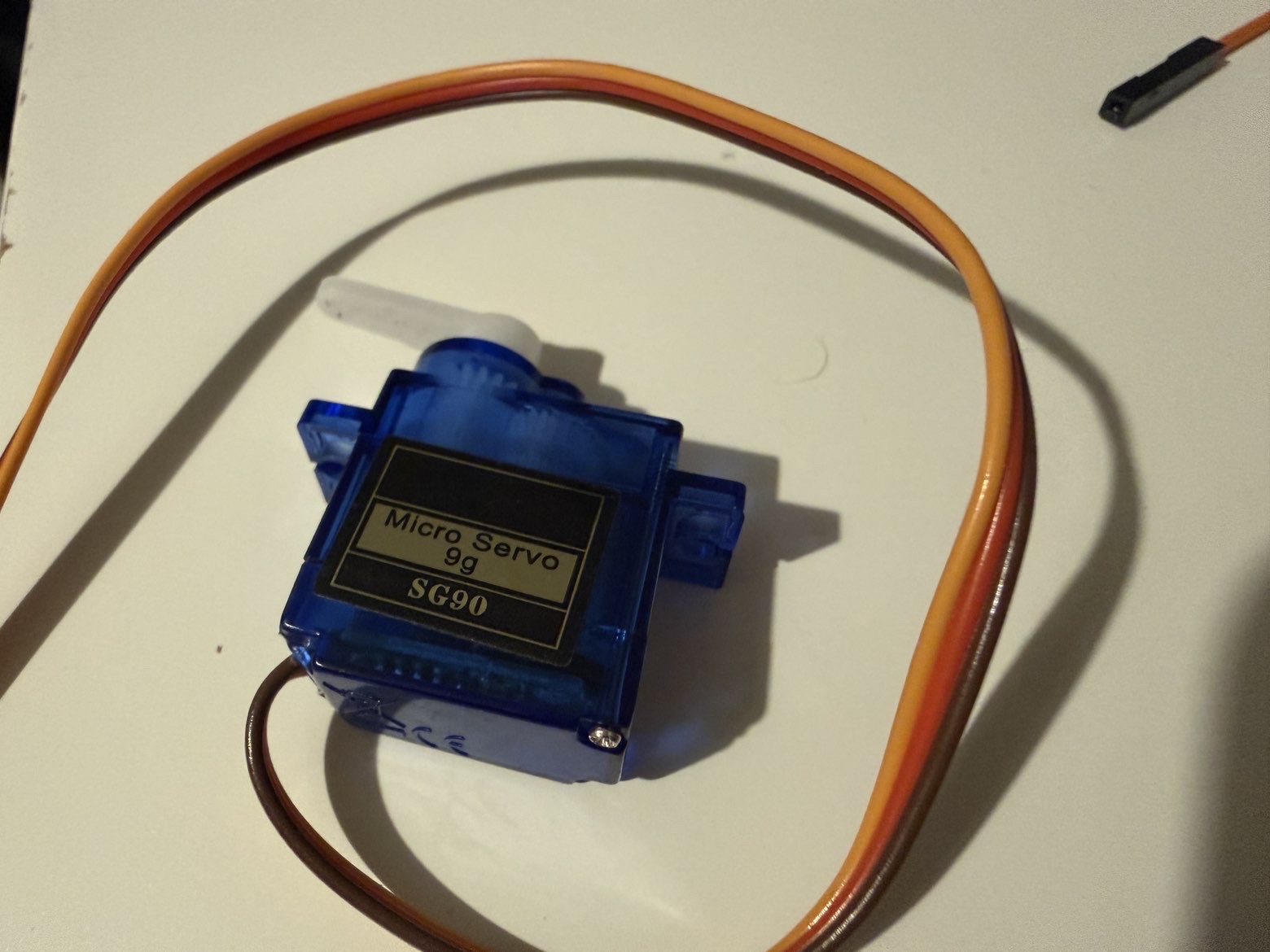
The second output device I used was an SG90 servo motor.
Unlike the RGB LED, which gives visual light output, the servo produces mechanical movement. This made it a good example of a physical output device.
Why I chose it
I chose the SG90 because:
- it is a very common actuator
- it is simple to control from a microcontroller
It also helped me compare visual output with physical output.
Wiring
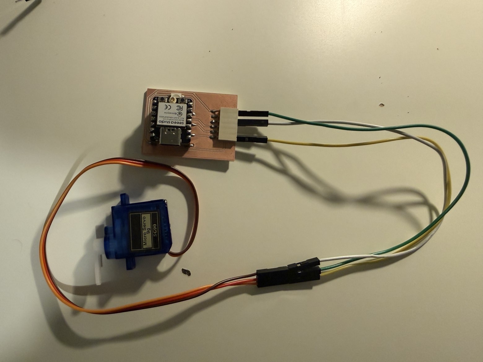
For this test, I connected:
- VCC -> 5V
- GND -> GND
- signal -> GPIO4
The servo used the modular connector on my board for power and signal access.
How it works
A servo motor does not spin continuously like a normal DC motor. Instead, it moves to a target angle based on a control pulse.
In this case:
- the ESP32 sends a control signal from a GPIO pin
- the servo interprets that signal as a position
- the shaft rotates to the corresponding angle
Code
#include <ESP32Servo.h>

Servo myServo;

const int SERVO_PIN = 4;

void setup() {
  myServo.setPeriodHertz(50);
  myServo.attach(SERVO_PIN, 500, 2400);
}

void loop() {
  myServo.write(0);
  delay(1000);

  myServo.write(90);
  delay(1000);

  myServo.write(180);
  delay(1000);
}
How the code works
In this code:
- the ESP32Servo library is used
- the servo signal is connected to GPIO4
- the servo is attached with standard pulse limits
- the shaft moves between:
- 0°
- 90°
- 180°
Result
The SG90 moved correctly between the programmed angles. This demonstrated that the board could control an actuator and create repeatable motion output.
Video
What I learned
The servo was useful because it introduced motion control. Compared with the RGB LED, it required more attention to power and timing, but it gave a much more physical kind of output.
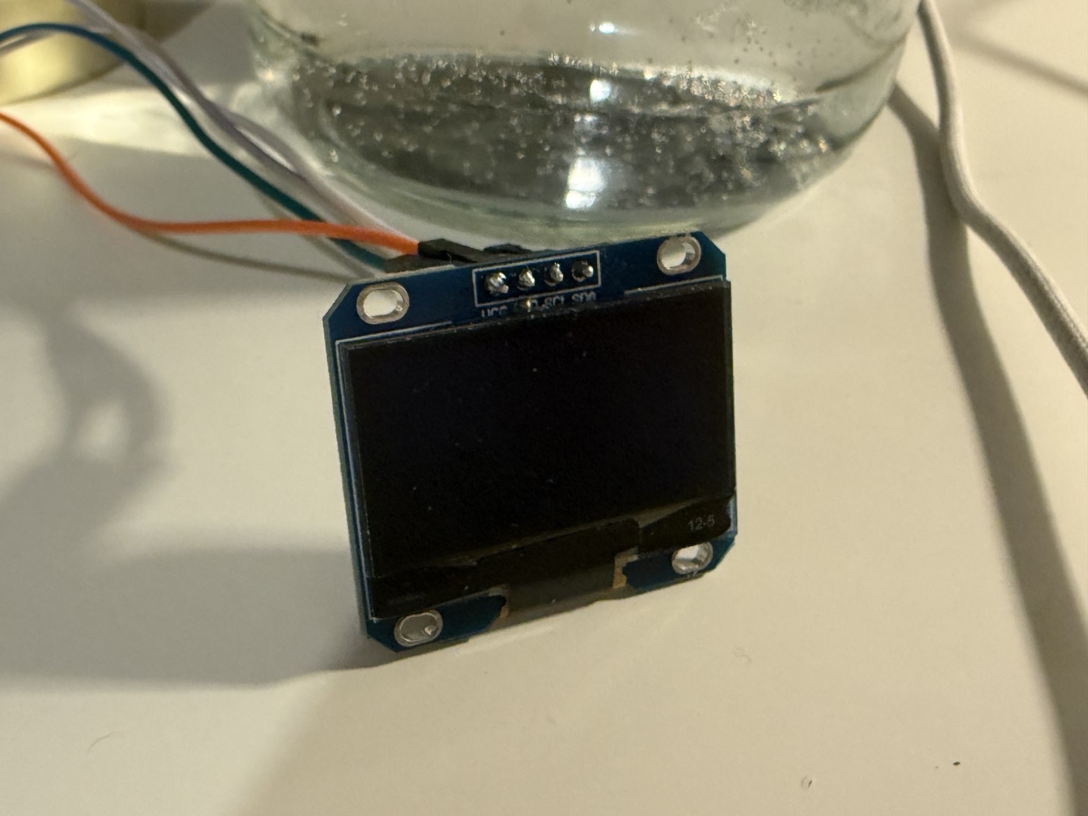
Output Device 3 - I2C OLED Display (SH110X)
Device overview
The third output device I used was an SH110X I2C OLED display.
This output device was different from both the RGB LED and the servo because it can display text and graphics, not just light or motion.
Why I chose it
I chose the OLED because:
- it uses the board’s I2C-ready connections
- it can display structured visual output
- it is useful for future projects where feedback needs to be shown clearly
This made it a good example of an information-based output device.
Wiring
For the OLED test, I connected:
- VCC -> 3.3V
- GND -> GND
- SDA -> GPIO6
- SCL -> GPIO7
How it works
The OLED communicates through I2C, so instead of controlling each pixel directly through many wires, the ESP32 sends display commands and data through the SDA and SCL lines.
That means the microcontroller can:
- print text
- draw shapes
- refresh the screen content dynamically
Code
#include <Wire.h>
#include <Adafruit_GFX.h>
#include <Adafruit_SH110X.h>

#define SCREEN_WIDTH 128
#define SCREEN_HEIGHT 64

Adafruit_SH1106G display(SCREEN_WIDTH, SCREEN_HEIGHT, &Wire, -1);

void setup() {
  Wire.begin(6, 7);

  if (!display.begin(0x3C, true)) {
    while (1);
  }

  display.clearDisplay();
  display.setTextSize(1);
  display.setTextColor(SH110X_WHITE);
  display.setCursor(0, 0);
  display.println("Week 10");
  display.println("Output Devices");
  display.display();
  delay(1000);
}

void loop() {
  display.clearDisplay();

  display.setTextSize(1);
  display.setCursor(0, 0);
  display.println("OLED Test Poyraz");

  display.drawRect(0, 20, 60, 20, SH110X_WHITE);
  display.fillRect(50, 20, 40, 20, SH110X_WHITE);

  display.setCursor(0, 50);
  display.println("XIAO ESP32-C3");

  display.display();
  delay(1000);
}
How the code works
In this code:
- Wire.begin(6, 7) initializes I2C using my board’s SDA and SCL pins
- the OLED is initialized at address 0x3C
- text and simple graphics like rectangles are drawn on the display
- the screen is refreshed with
display.display()
Result
The OLED successfully displayed text and graphics. Compared with the other outputs, it gave the most information-rich result because it could show readable data rather than only light or movement.
Video
What I learned
The OLED showed me that output devices can also be used as interfaces. It was not just an indicator, but a way of communicating information clearly to the user.
Problems and Fixes
I2C device setup
For the OLED, the most important part was correct I2C wiring if the pins do not match, the display will not initialize.
I also initially used the wrong library for my oled. I used SSD1306 but then switched to SH110X.
Reflection
This week helped me understand that different output devices require very different workflows even when they are connected to the same board.
The most useful part for me was reusing the same modular board from Week 09 and testing several kinds of outputs on it. This made it easier to compare different forms of actuation and feedback without redesigning the electronics from the beginning.
The clearest takeaway for me was:
- an RGB LED gives simple programmable visual feedback
- a servo motor gives controlled physical movement
- an OLED display gives structured visual information
Together, these three devices showed three very different ways a microcontroller can interact with the physical world.