Introduction
This week focused on networking and communications. Instead of treating the OLED only as an output device like I did in Week 10, I wanted to understand the communication behind it more clearly.
For this assignment, I reused my modular Seeed XIAO ESP32-C3 board from Week 09 and the I2C OLED display that I tested in Week 10. The main goal was to explore I2C as a bus communication protocol, scan the bus, identify the OLED address, and then use that address in my code to control the display.
The setup for this week was simple, but it helped me understand an important idea: in I2C, the microcontroller is not just sending random signals to a screen. It communicates with a device at a specific bus address.
For Week 11, I worked with:
- XIAO ESP32-C3 board from my previous weeks
- SH110X 128x64 I2C OLED display
- SDA and SCL communication lines
- I2C scanner code
- OLED display code using the detected bus address
Group Assignment:
https://week-11-group-assignment-393041.fabcloud.io
The OLED is the local output device, and it is selected through its I2C bus address. This allowed me to satisfy the networking and communication part of the assignment without making the documentation unnecessarily complicated.
Board Used
I reused the same modular XIAO ESP32-C3 board from my Week 09 and Week 10 assignments.
I did not design a new board for this week because the assignment allows using a board that was designed and fabricated earlier. My board was already suitable because it exposed:
- 3.3V
- GND
- SDA
- SCL
- GPIO pins
This made it easy to connect an I2C device and focus on the communication protocol itself.
Why I Chose I2C
I chose I2C because it is one of the most common communication protocols used between microcontrollers and small modules.
The useful part of I2C is that it only needs two communication wires:
- SDA, which carries the data
- SCL, which carries the clock signal
Multiple devices can share the same SDA and SCL lines as long as each device has its own address. In my setup I only used one I2C device, but the addressing idea is still visible because the OLED responds at address 0x3C.
This was different from Week 10. In Week 10, I mainly cared about making the display show text and shapes. This week, I focused more on how the ESP32 finds and talks to the display.
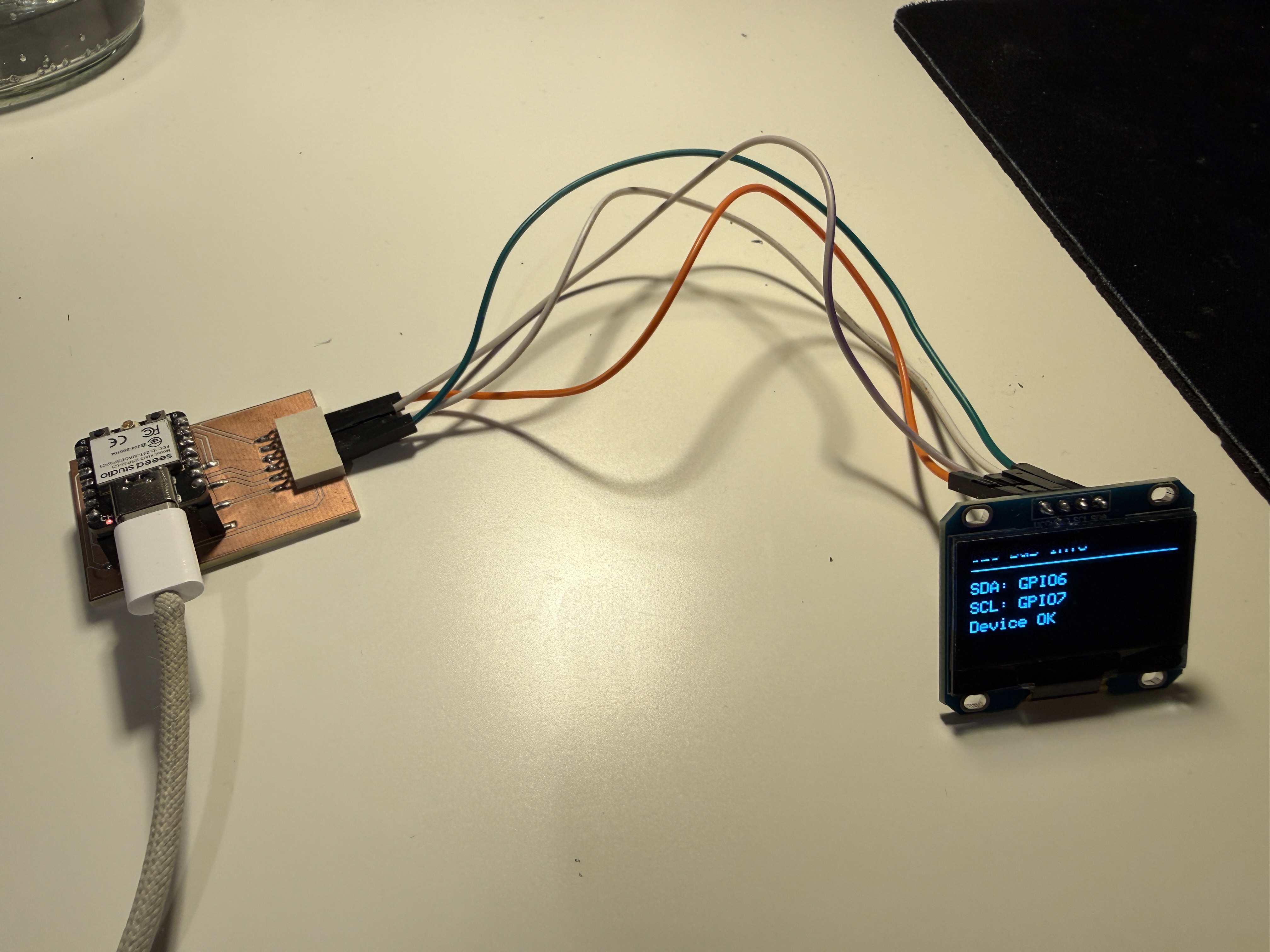
Hardware Setup
Components
- Seeed XIAO ESP32-C3 board
- SH110X 128x64 OLED display
- Jumper wires
- USB cable for power and programming
Wiring
For the OLED, I used the same I2C pins as before:
| OLED Pin | XIAO ESP32-C3 Connection |
|---|---|
| VCC | 3.3V |
| GND | GND |
| SDA | GPIO6 |
| SCL | GPIO7 |
I2C Addressing
The most important part of this week was understanding the address.
When an I2C device is connected to the bus, the microcontroller does not control it by pin number only. Instead, the microcontroller sends data to a bus address.
In my case, the OLED display was found at:
0x3C
That means the ESP32 sends commands to address 0x3C, and the OLED responds.
This is the main addressing used in my project:
| Part | Address / Identity |
|---|---|
| OLED display | 0x3C |
| SDA pin | GPIO6 |
| SCL pin | GPIO7 |
Step 1 - Scanning the I2C Bus
Before writing the OLED display program, I first used an I2C scanner.
The scanner checks all possible I2C addresses and prints which devices respond. This was useful because it confirmed that:
- the wiring was correct
- SDA and SCL were assigned correctly
- the OLED was alive
- the address was
0x3C
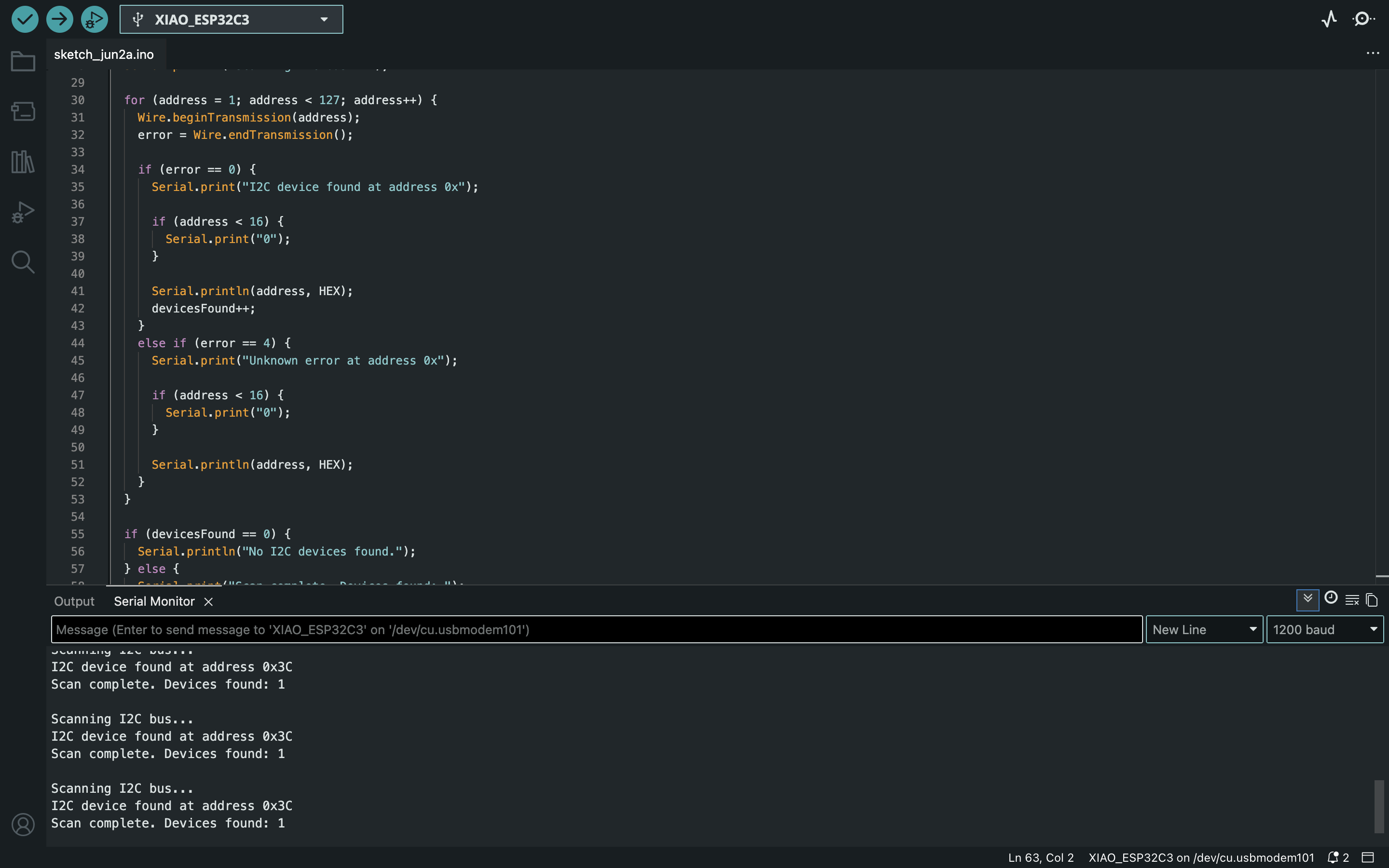
I2C Scanner Code
#include <Wire.h>

#define SDA_PIN 6
#define SCL_PIN 7

void setup() {
  Serial.begin(115200);
  delay(1000);

  Serial.println();
  Serial.println("Week 11 - I2C Scanner");
  Serial.println("Starting I2C bus on custom pins...");

  Wire.begin(SDA_PIN, SCL_PIN);

  Serial.print("SDA pin: ");
  Serial.println(SDA_PIN);
  Serial.print("SCL pin: ");
  Serial.println(SCL_PIN);
}

void loop() {
  byte error;
  byte address;
  int devicesFound = 0;

  Serial.println();
  Serial.println("Scanning I2C bus...");

  for (address = 1; address < 127; address++) {
    Wire.beginTransmission(address);
    error = Wire.endTransmission();

    if (error == 0) {
      Serial.print("I2C device found at address 0x");

      if (address < 16) {
        Serial.print("0");
      }

      Serial.println(address, HEX);
      devicesFound++;
    }
    else if (error == 4) {
      Serial.print("Unknown error at address 0x");

      if (address < 16) {
        Serial.print("0");
      }

      Serial.println(address, HEX);
    }
  }

  if (devicesFound == 0) {
    Serial.println("No I2C devices found.");
  } else {
    Serial.print("Scan complete. Devices found: ");
    Serial.println(devicesFound);
  }

  delay(3000);
}
(Got this scanner code from ChatGPT)
Scanner Result
The OLED was detected at:
I2C device found at address 0x3C
This was the point where the communication setup started to make more sense to me. The screen was not just connected to the board physically. It was a device on a bus, and the ESP32 needed to communicate with the correct address.
Step 2 - Displaying the Address on the OLED
After confirming the I2C address, I wrote a second program that initialized the OLED at 0x3C and displayed a small status screen.
This made the output more meaningful than just printing random text. The OLED displayed:
- the week number
- the protocol
- the bus address
- the SDA and SCL pins
- the node name
OLED Address Display Code
#include <Wire.h>
#include <Adafruit_GFX.h>
#include <Adafruit_SH110X.h>

#define SDA_PIN 6
#define SCL_PIN 7

#define SCREEN_WIDTH 128
#define SCREEN_HEIGHT 64
#define OLED_ADDR 0x3C

Adafruit_SH1106G display(SCREEN_WIDTH, SCREEN_HEIGHT, &Wire, -1);

const char* nodeID = "oled_node_01";

bool checkI2CDevice(byte address) {
  Wire.beginTransmission(address);
  byte error = Wire.endTransmission();

  if (error == 0) {
    return true;
  } else {
    return false;
  }
}

void drawStatusScreen() {
  display.clearDisplay();

  display.setTextSize(1);
  display.setTextColor(SH110X_WHITE);

  display.setCursor(0, 0);
  display.println("Week 11");

  display.setCursor(0, 12);
  display.println("Networking + Comm");

  display.drawLine(0, 24, 127, 24, SH110X_WHITE);

  display.setCursor(0, 30);
  display.println("Protocol: I2C");

  display.setCursor(0, 40);
  display.println("Address: 0x3C");

  display.setCursor(0, 50);
  display.println("Node: oled_node_01");

  display.display();
}

void drawBusScreen() {
  display.clearDisplay();

  display.setTextSize(1);
  display.setTextColor(SH110X_WHITE);

  display.setCursor(0, 0);
  display.println("I2C Bus Info");

  display.drawLine(0, 12, 127, 12, SH110X_WHITE);

  display.setCursor(0, 20);
  display.println("SDA: GPIO6");

  display.setCursor(0, 32);
  display.println("SCL: GPIO7");

  display.setCursor(0, 44);
  display.println("Device OK");

  display.display();
}

void setup() {
  Serial.begin(115200);
  delay(1000);

  Serial.println();
  Serial.println("Week 11 - OLED I2C Node");

  Wire.begin(SDA_PIN, SCL_PIN);

  Serial.print("Checking OLED at address 0x");
  Serial.println(OLED_ADDR, HEX);

  if (!checkI2CDevice(OLED_ADDR)) {
    Serial.println("OLED not found. Check wiring or address.");

    while (true) {
      delay(1000);
    }
  }

  Serial.println("OLED found.");

  if (!display.begin(OLED_ADDR, true)) {
    Serial.println("OLED library initialization failed.");

    while (true) {
      delay(1000);
    }
  }

  display.clearDisplay();
  display.display();

  drawStatusScreen();
}

void loop() {
  drawStatusScreen();
  delay(2000);

  drawBusScreen();
  delay(2000);

  Serial.print("Node ");
  Serial.print(nodeID);
  Serial.print(" is active at I2C address 0x");
  Serial.println(OLED_ADDR, HEX);
}
How the Code Works
The code starts by including the libraries:
Wire.hfor I2C communicationAdafruit_GFX.hfor drawing text and shapesAdafruit_SH110X.hfor controlling the SH110X OLED display
The important line for my board is:
Wire.begin(SDA_PIN, SCL_PIN);
This tells the ESP32 to use GPIO6 as SDA and GPIO7 as SCL.
Then the code checks whether a device responds at:
0x3C
If the device is found, the display is initialized and the OLED shows the status screens. If the OLED is not found, the program stops and prints an error in the Serial Monitor. I added this because it makes debugging much easier.
Result
The OLED successfully responded at address 0x3C, and the display showed the I2C information correctly.
This confirmed that:
- the board can communicate over I2C
- the OLED has a working bus address
- the SDA and SCL pins are correct
- the OLED can be used as a local output device
- the code can address the device intentionally instead of just assuming it is connected
Additional Test - Wi-Fi Button Node
After the evaluation feedback, I understood that my I2C OLED test was useful for explaining bus addressing, but it was still mostly a board communicating with a display module. To make the networking part clearer, I added one more test where my programmable board sends data to another device over Wi-Fi.
For this test, I reused the board that I had already made in the previous weeks. This board already had a push button integrated on it, so I did not need to fabricate a new board. The idea was simple: when I press the button on my ESP32-C3 board, the board sends a message to a Flask server running on my laptop, and the message appears on a browser page.
This made the assignment closer to a real network example because the result was not only happening on a local display. The input happened on my custom board, but the output appeared on a separate computer through the local Wi-Fi network.
Goal of This Test
The goal was to make the button on my board work as a small network node.
In this setup:
- the ESP32-C3 board reads the integrated button
- the board connects to the same Wi-Fi network as my laptop
- the board sends an HTTP POST request when the button is pressed
- the message is sent in JSON format
- my laptop receives the message with a Flask server
- the browser page updates and shows the latest button press
Communication Diagram
[Integrated button on my board]
              |
              v
      [Seeed XIAO ESP32-C3]
              |
              v
          Wi-Fi network
              |
              v
      [Flask server on laptop]
              |
              v
       [Browser status page]
Hardware Used
| Part | Use |
|---|---|
| Previous ESP32-C3 board | Programmable Wi-Fi node |
| Integrated button | Physical input |
| Laptop | Flask server and browser output |
| USB cable | Power and programming |
| Local Wi-Fi network | Communication between the board and laptop |
The USB cable was only used to power and program the board. The actual communication happened through Wi-Fi.
Button Pin
My board already had the button connected, so I reused it as the input for this network test.
#define BUTTON_PIN D7
pinMode(BUTTON_PIN, INPUT_PULLUP);
Because the button is connected to ground when pressed, I used the internal pull-up resistor. This means the reading is HIGH when the button is not pressed and LOW when the button is pressed.
| Button state | ESP32 reading |
|---|---|
| Not pressed | HIGH |
| Pressed | LOW |
Message Format
When the button is pressed, the ESP32 sends this type of JSON message to the laptop:
{
  "node_id": "button_node_01",
  "input": "integrated_button",
  "state": "pressed"
}
I included a node_id because this makes the system easier to expand later. If I had more boards, each board could send messages with a different node name.
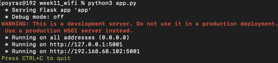
Step 3 - Setting Up the Flask Server
First, I made a small Flask server on my laptop. The server has one route for receiving the button message and one browser page for displaying the latest message.
Installing Flask
I used a Python virtual environment:
python3 -m venv venv
source venv/bin/activate
python3 -m pip install flask
Finding the Laptop IP Address
The ESP32 needs the local IP address of the laptop. On my Mac, I used:
ipconfig getifaddr en0
This gives an address like:
192.168.1.xxx
I used this address in the ESP32 code. I did not use 127.0.0.1, because that would point back to the ESP32 itself instead of my laptop.
Flask Code
I saved this as app.py:
from flask import Flask, request, jsonify, render_template_string
from datetime import datetime

app = Flask(__name__)

latest_data = {
    "node_id": "waiting",
    "input": "none",
    "state": "none",
    "sender_ip": "none",
    "time": "-"
}

history = []

HTML_PAGE = """
<!DOCTYPE html>
<html>
<head>
    <meta charset="UTF-8">
    <title>ESP32-C3 Button Node</title>
    <script>
        async function refreshData() {
            const latestResponse = await fetch('/latest');
            const latest = await latestResponse.json();

            document.getElementById('node').textContent = latest.node_id;
            document.getElementById('input').textContent = latest.input;
            document.getElementById('state').textContent = latest.state;
            document.getElementById('sender').textContent = latest.sender_ip;
            document.getElementById('time').textContent = latest.time;

            const historyResponse = await fetch('/history');
            const history = await historyResponse.json();
            const list = document.getElementById('history');
            list.innerHTML = '';

            history.slice().reverse().forEach(item => {
                const li = document.createElement('li');
                li.textContent = item.time + ' | ' + item.node_id + ' | ' + item.input + ' | ' + item.state;
                list.appendChild(li);
            });
        }

        setInterval(refreshData, 500);
        window.onload = refreshData;
    </script>
</head>
<body style="font-family: Arial, sans-serif; padding: 30px;">
    <h1>ESP32-C3 Button Node</h1>

    <h2>Latest Received Message</h2>
    <p><strong>Node ID:</strong> <span id="node">-</span></p>
    <p><strong>Input:</strong> <span id="input">-</span></p>
    <p><strong>State:</strong> <span id="state">-</span></p>
    <p><strong>Sender IP:</strong> <span id="sender">-</span></p>
    <p><strong>Time:</strong> <span id="time">-</span></p>

    <h2>Message History</h2>
    <ul id="history"></ul>
</body>
</html>
"""

@app.route('/')
def index():
    return render_template_string(HTML_PAGE)

@app.route('/button', methods=['POST'])
def button():
    global latest_data, history

    data = request.get_json(silent=True)

    if not data:
        return jsonify({"status": "error", "message": "No JSON received"}), 400

    latest_data = {
        "node_id": data.get("node_id", "unknown"),
        "input": data.get("input", "unknown"),
        "state": data.get("state", "unknown"),
        "sender_ip": request.remote_addr,
        "time": datetime.now().strftime("%H:%M:%S")
    }

    history.append(latest_data.copy())

    if len(history) > 20:
        history = history[-20:]

    print("Received:", latest_data)

    return jsonify({
        "status": "ok",
        "received": latest_data
    })

@app.route('/latest')
def latest():
    return jsonify(latest_data)

@app.route('/history')
def get_history():
    return jsonify(history)

if __name__ == '__main__':
    app.run(host='0.0.0.0', port=5050, debug=True)
*Flask server’s code is generated from ChatGPT because I was unfamiliar with it.
I ran the server with:
python3 app.py
Then I opened this address in the browser:
http://MY_LAPTOP_IP:5050
At this point the page was waiting for a message from the ESP32.
Step 4 - Programming the ESP32-C3 Button Node
The ESP32 code connects to Wi-Fi, reads the integrated button, and sends a JSON message to the Flask server when the button is pressed.
Before uploading the code, I changed these values:
YOUR_WIFI_NAMEYOUR_WIFI_PASSWORDYOUR_LAPTOP_IP
ESP32 Code
#include <WiFi.h>
#include <HTTPClient.h>
const char* ssid = "YOUR_WIFI_NAME";
const char* password = "YOUR_WIFI_PASSWORD";
const char* serverURL = "http://YOUR_LAPTOP_IP:5050/button";
#ifndef D7
#define D7 20
#endif
#define BUTTON_PIN D7
const char* nodeID = "button_node_01";
int lastButtonState = HIGH;
unsigned long lastSendTime = 0;
const unsigned long debounceDelay = 200;
void connectWiFi() {
WiFi.begin(ssid, password);
Serial.print("Connecting to Wi-Fi");
while (WiFi.status() != WL_CONNECTED) {
delay(500);
Serial.print(".");
}
Serial.println();
Serial.println("Wi-Fi connected");
Serial.print("ESP32 IP address: ");
Serial.println(WiFi.localIP());
}
void sendButtonPress() {
if (WiFi.status() != WL_CONNECTED) {
Serial.println("Wi-Fi not connected. Message not sent.");
return;
}
HTTPClient http;
http.begin(serverURL);
http.addHeader("Content-Type", "application/json");
String json = "{";
json += "\"node_id\":\"" + String(nodeID) + "\",";
json += "\"input\":\"integrated_button\",";
json += "\"state\":\"pressed\"";
json += "}";
int responseCode = http.POST(json);
Serial.print("Sent JSON: ");
Serial.println(json);
Serial.print("HTTP response code: ");
Serial.println(responseCode);
http.end();
}
void setup() {
Serial.begin(115200);
delay(1000);
Serial.println();
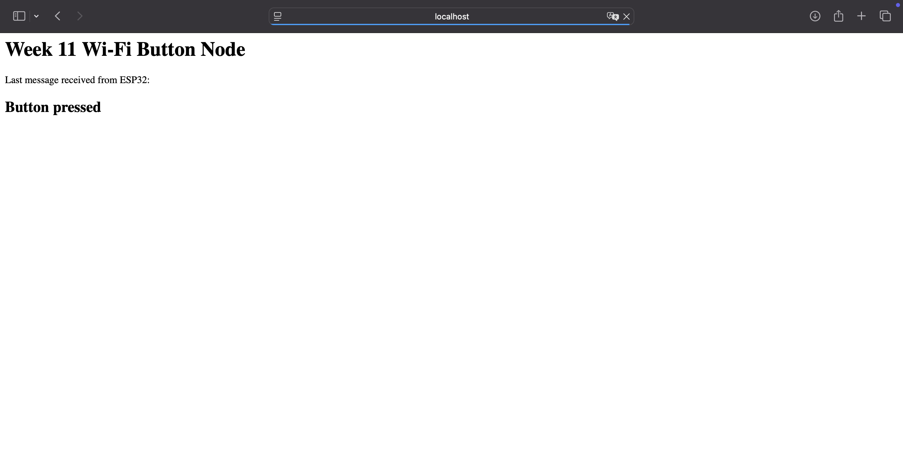
Serial.println("Week 11 Wi-Fi Button Node");
pinMode(BUTTON_PIN, INPUT_PULLUP);
connectWiFi();
}
void loop() {
if (WiFi.status() != WL_CONNECTED) {
Serial.println("Wi-Fi disconnected. Reconnecting...");
connectWiFi();
}
int currentButtonState = digitalRead(BUTTON_PIN);
if (currentButtonState == LOW && lastButtonState == HIGH) {
unsigned long now = millis();
if (now - lastSendTime > debounceDelay) {
Serial.println("Integrated button pressed");
sendButtonPress();
lastSendTime = now;
}
}
lastButtonState = currentButtonState;
delay(10);
}
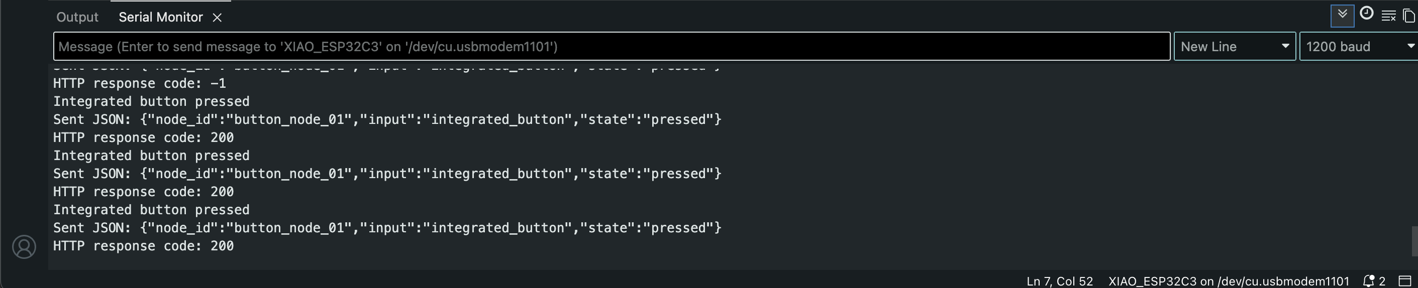
Step 5 - Testing the Wi-Fi Communication
To test the communication, I followed this order:
- Connected my laptop and ESP32-C3 to the same Wi-Fi network.
- Started the Flask server on my laptop.
- Opened the browser page at
http://MY_LAPTOP_IP:5050. - Uploaded the ESP32 code to my board.
- Pressed the integrated button on the board.
- Checked that the browser page updated.
- Checked that the Flask terminal printed the received JSON.
- Checked that the ESP32 Serial Monitor printed HTTP response code
200.
When the button was pressed, the ESP32 sent the JSON message to my laptop. The browser page showed button state.
Result of the Wi-Fi Test
The added test successfully created this communication path:
physical button press -> ESP32-C3 -> Wi-Fi -> HTTP POST -> Flask server -> browser update
This directly addressed the feedback because my programmable board was communicating with a computer over Wi-Fi. The board was not only using a display module anymore. It was sending a message to another system, and the browser interface changed because of the physical button press.
Problems and Fixes
Problem 1 - OLED library confusion
In Week 10, I first tried to use an SSD1306 library, but my display worked correctly with the SH110X library. This was important again this week because using the wrong OLED library can make the display look broken even when the wiring is correct.
Fix
I used:
#include <Adafruit_SH110X.h>
Problem 2 - SDA and SCL pin setup
At first, it is easy to assume that the board will automatically know which pins to use for I2C. Since I was using my own wiring, I wanted to be explicit.
Fix
I defined the pins clearly:
#define SDA_PIN 6
#define SCL_PIN 7
and started I2C with:
Wire.begin(SDA_PIN, SCL_PIN);
This made the code match my actual hardware setup.
Problem 3 - Address could be different
Many small OLED displays use 0x3C, but some can use 0x3D. If I only guessed the address, I could waste time debugging the wrong thing. (Got this information from ChatGPT, later checked it from other resouces as well.)
Fix
I ran the I2C scanner first. This confirmed that my display responded at 0x3C.
Reflection
This week helped me understand communication at two different levels. The first part with the OLED helped me understand I2C as an actual communication system, not just a way to connect a screen. Scanning the bus and finding the 0x3C address made it clearer that the ESP32 was communicating with an addressed device, not only sending signals to a display.
After the feedback, I also added the Wi-Fi button test using the board that I had already made with an integrated button. This part made the networking idea clearer for me because the input happened on my ESP32-C3 board, but the result appeared on my laptop through a browser page. Instead of only controlling a local output, the board sent a message over Wi-Fi to another system.
This also connects to my final project direction. If I use displays, sensors, physical buttons, or a web interface later, I will need to understand how information moves between different parts of the system. This week made that idea much clearer because I tested both a local bus communication example and a Wi-Fi communication example.