3D Scanning and Printing (WEEK 6)
Individual Assignment:
- design and 3D print an object (small, few cm3, limited by printer time) that could not be made subtractively
- 3D scan an object (and optionally print it)
Group Assignment:
- Test the design rules for your 3D printer(s)
IMPORTANT NOTE : ALL OF MY IMAGES ARE POP UP IMAGES , IF YOU HAVE ANY PROBLEM READINGS THOSE IMAGES , PLEASE CLICK ON THEM AND THEY WILL ENLARGE AUTOMATICALLY AND YOU CAN READ THEM EASILY
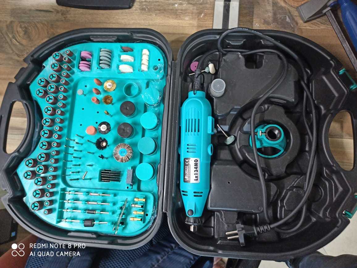
Machine in our lab
1. ULTIMAKER 2+

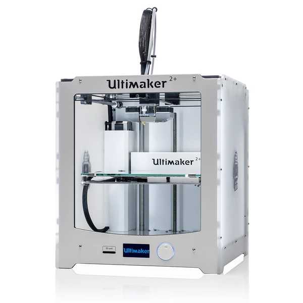
Designed by experts and enriched by our global community, Ultimaker 2+ and Ultimaker 2 Extended+ perform even complex 3D printing tasks with ease. They excel at printing bridging, overhangs, and accurate details. This enables you to create high-quality results, tailored to your business.
Specification of printer
* Build volume: up to 223 x 223 x 305 mm (8.8 x 8.8 x 12 inches)
* Up to 20 micron (0.001 inch) layer resolution
* Print head travel speed: 300 mm/s
* Open filament system – print with any 2.85 mm material
For more information about printer you can click on this link
* Software which is used for slicing and creating g-codes and m-codes for ultimaker is
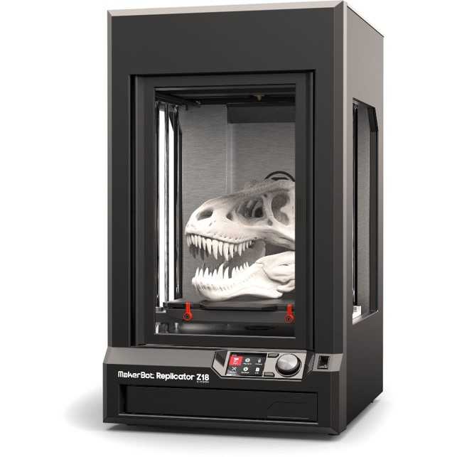
2. MakerBot Replicator Z-18

It is is an Fifth Generation Smart 3d printer which can provide very fine 3D Prints.
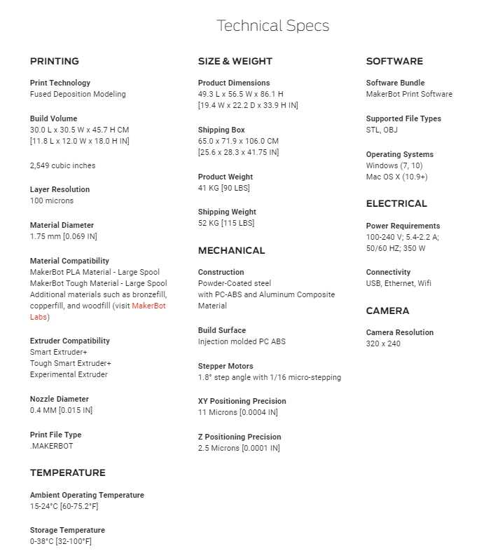
This is is the specsheet of machine and for more information you can click on this link
Software which is used for slicing in Stratasys is
* Pls check
, it is an free site which is made by Makerbot team where creaters post different stl file of 3D and 2d object and we can download
any file and print it any way we like it for free
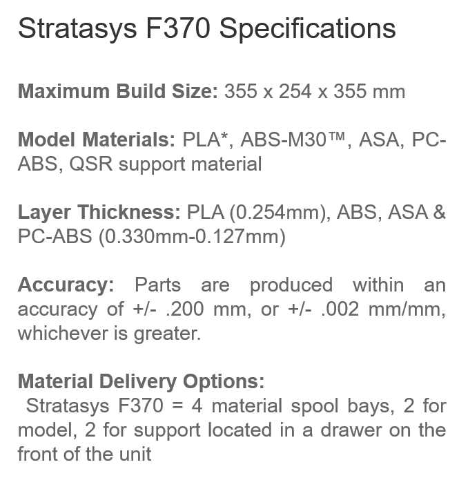
3. Stratasys F370

This is one of the best machine
* Software which is used for slicing in Stratasys is
* Pls check , it is an free site which is made by Stratasys team where creaters post different stl file of 3D and 2d object and we can download
any file and print it any way we like it for free
Group Assignment:
For group assignment we have to print some variouse test print to check the capability of our machine
Variouse test we are going to perform are as follow
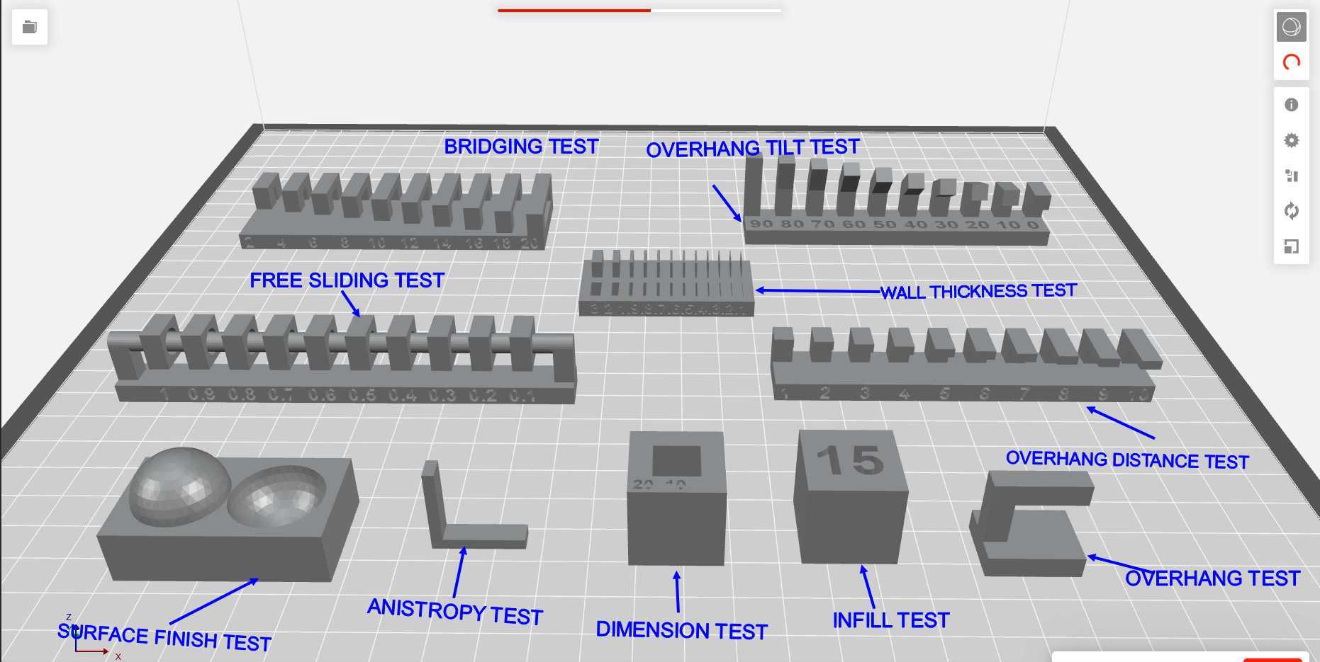
Overhang test
* Overhang tilt test
* Overhang distance test
* Bridging test
* Wall thickness test
* Dimensions test
* Anisotropy test
* Surface finish test
* Infill test
* Clearence test
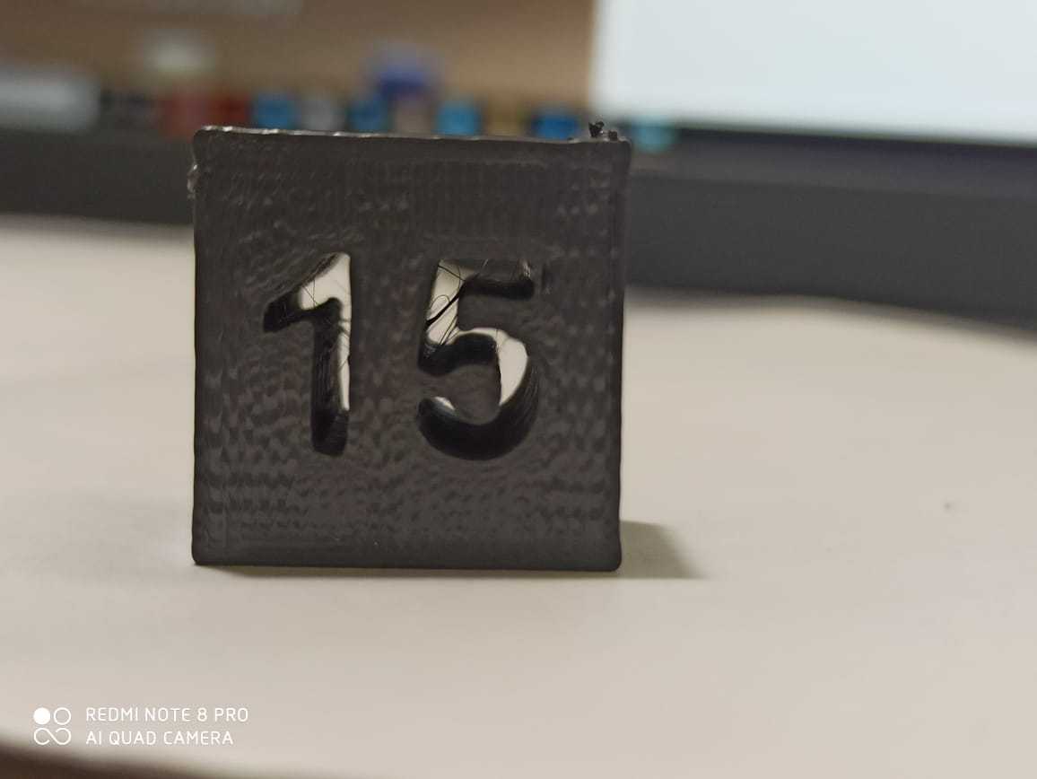
Printing parrameters(These parameters will same for all parts)
Printing material : Tough PLA
Infill : 10%
Layer height: 0.20 mm Nozzle
temp :215 C
Support : no support
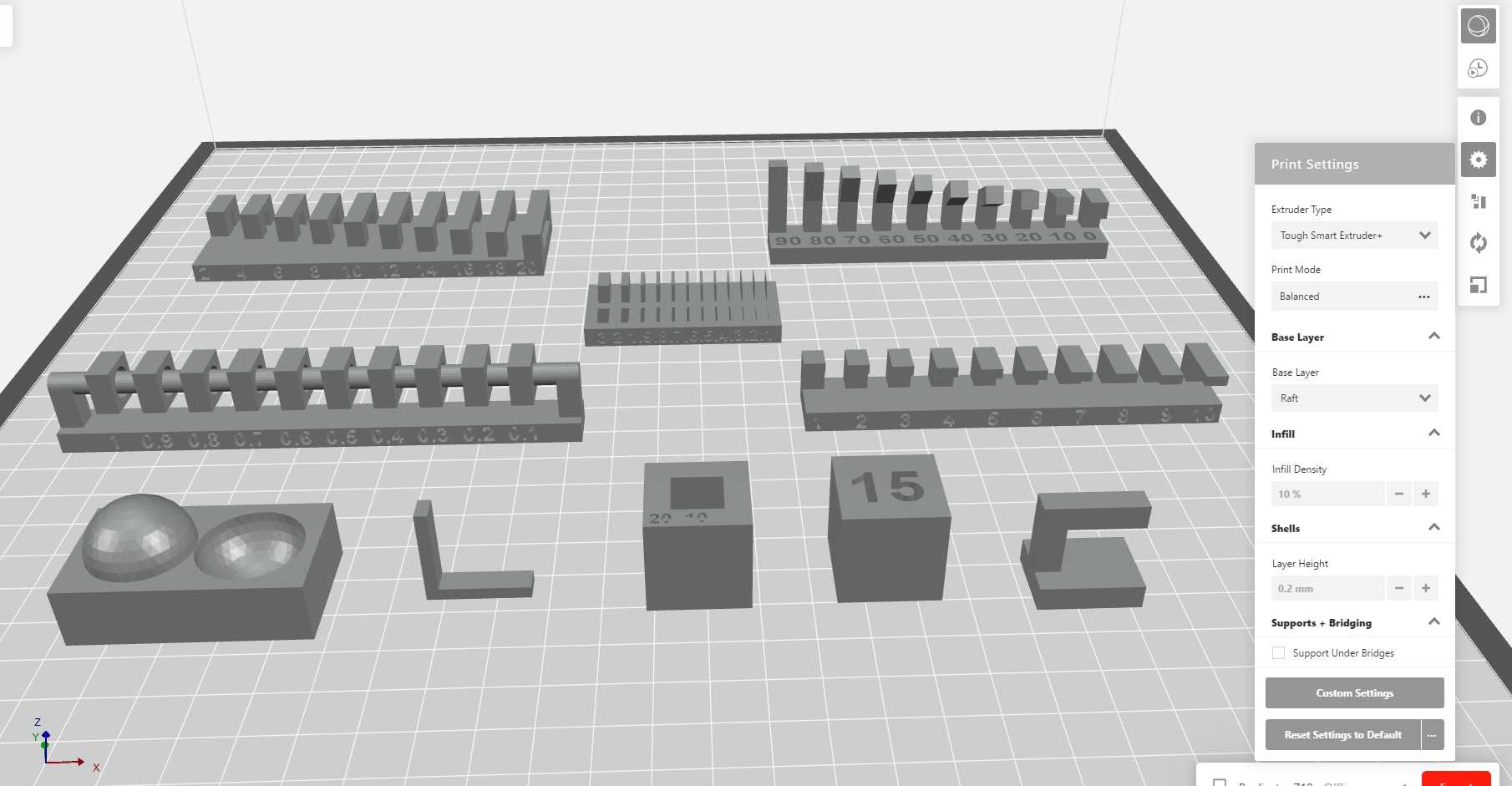
After i added all the stl of test in makerbot slicer , now i need to give the parameters for slicing
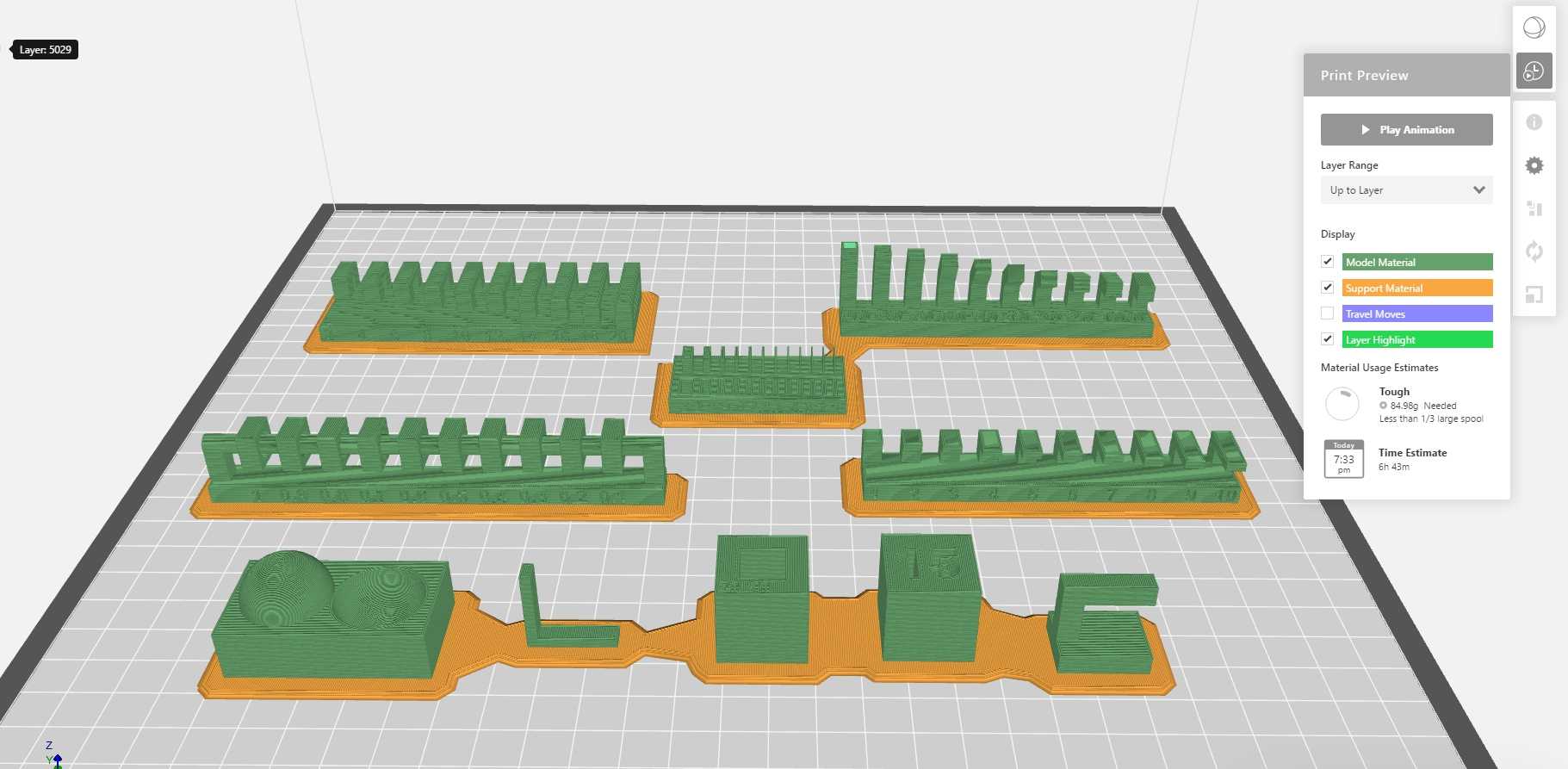
The slicer software shows me 6hr48m print time and i then exported the file for printing
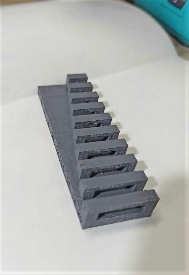
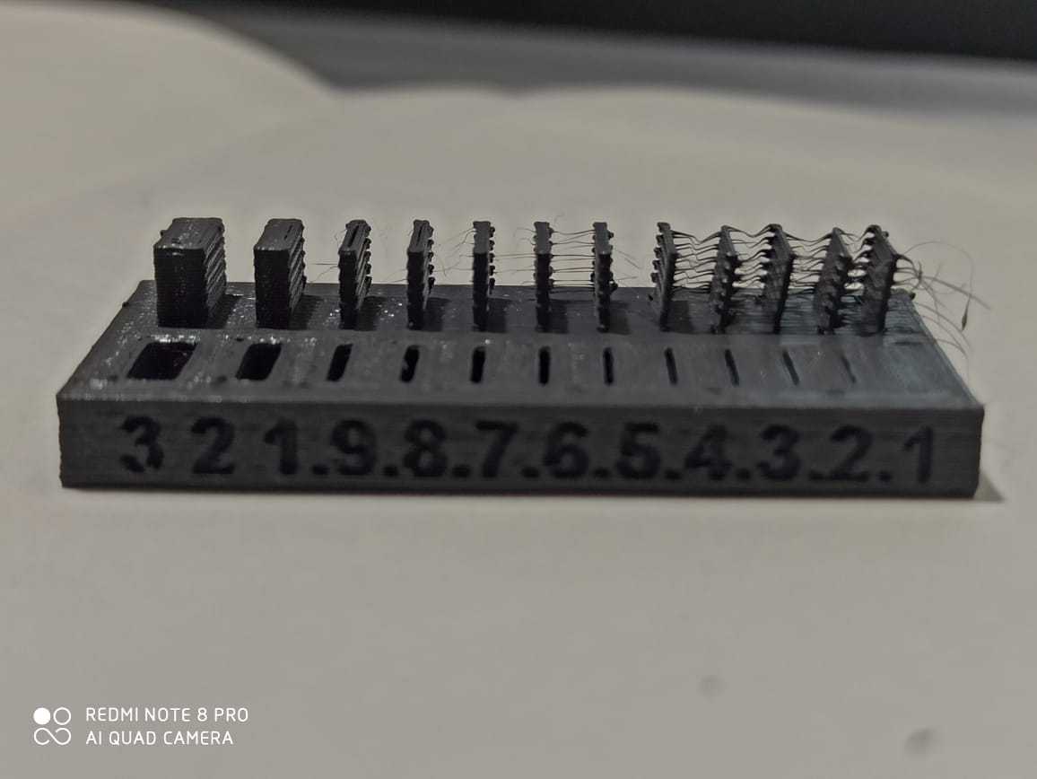
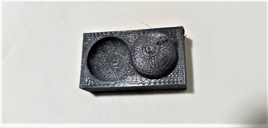
1. Overhang test
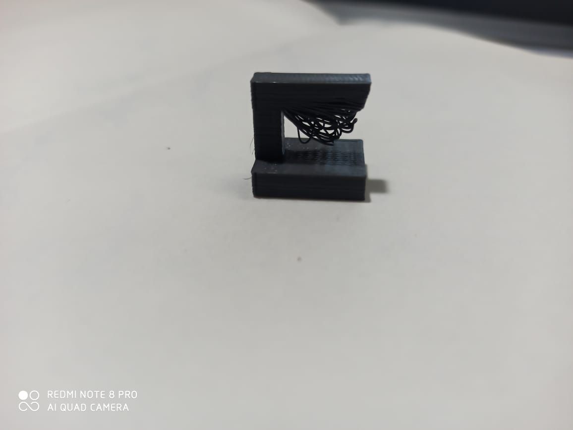
Test conclusion
Through this test you can see that you can't make pieces having large overhang or dont have support
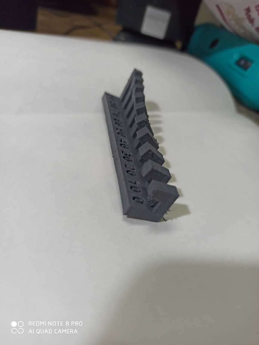
2. Overhang tilt test
Overhangs are the bane of engineers and designers who work in 3D printing. A 3D printing overhang is any part of a print that extends outward, beyond the previous layer, without any direct support.
To illustrate the concept, let’s look at a real life structure that could be considered to have a mild overhang: The Leaning Tower of Pisa. On the side that’s closer to the ground, we would say it has
an overhang of 3.99 degrees. Notice that, when measuring overhang angles, we measure “down” from the vertical axis.
Test conclusion
The test showed that 0 , 10 ,20 overhang doesn't print well as they require support for that as you have seen in above test , but after angle of 20 , it shows good result and it doesn't require support.
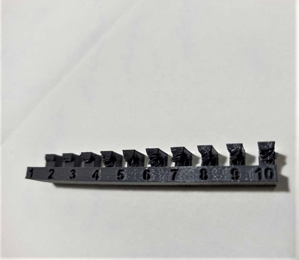
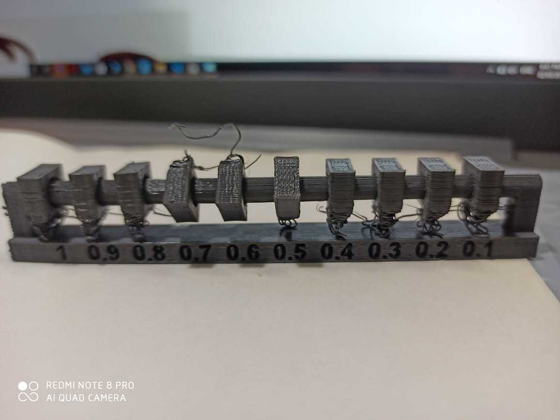
3. Overhang distance test
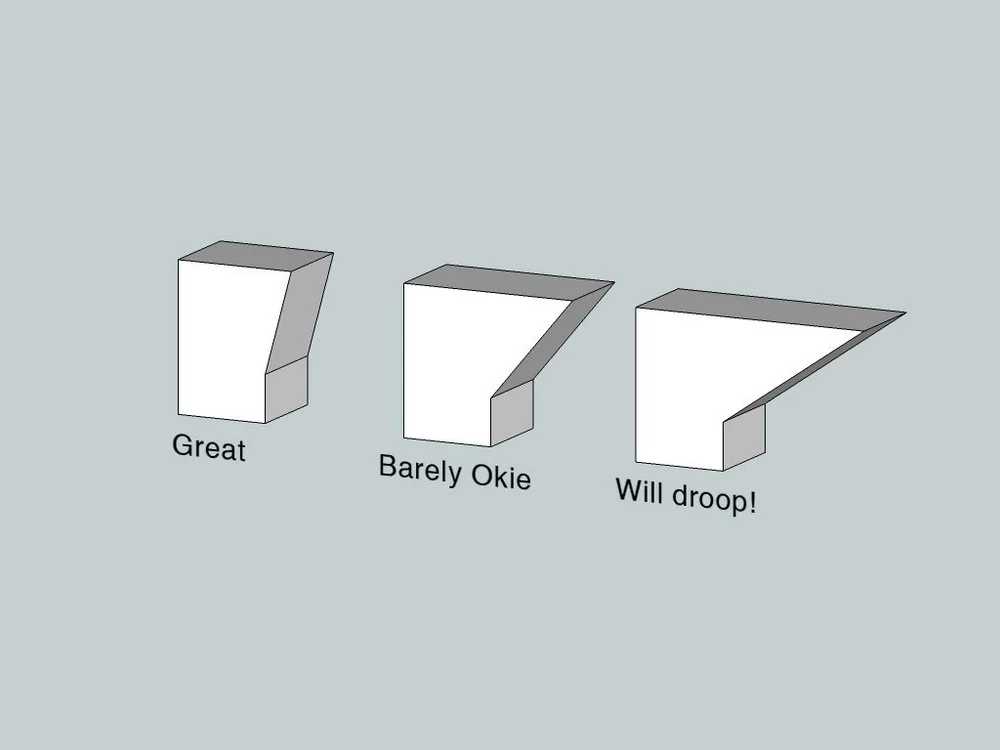
While a concern for Pisa preservationists, most 3D printers wouldn’t have any problems 3D printing overhangs of 3.99 degrees. Usually, overhangs up to 45 degrees can still be printed without loss of quality.
That’s because any layer in a 45-degree overhang is 50% supported by the layer beneath. In other words, each new layer has enough support to remain intact and to make printing possible.
However, anything past 45 degrees approaches the horizontal and becomes difficult to print. Such overhangs are prone to curling, sagging, delamination, or collapsing. Exceeding 45 degrees means every
new layer has less of the previous layer to bond with. This translates to a poor quality print with droopy filament strands.
This is why many designers try to avoid overhangs beyond 45 degrees. But for those who don’t want to limit their creativity and their designs, the 45-degree rule is not always the best solution.
Many objects need questionable overhangs to function or to maintain their beauty. For that reason, we’ve compiled a number of tips and tricks to help you break free of 45-degree prison.
Test conclusion
The test showes us that The test piece started to getting distorted just after 5 mm of the overhang. there were strings of the material which were coming out after 5mmdue to lack of support.
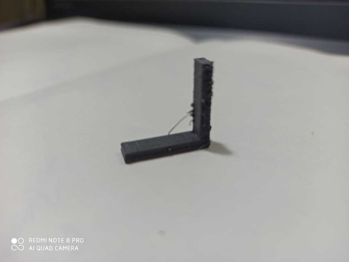
4. Bridging test
Bridging in 3D printing is an extrusion of material that horizontally links two raised points. However, if you are reading this article, the bridges in your prints are probably not too horizontal. Don’t beat yourself up. Bridging problems are extremely common, and (take a deep breath) are relatively easy to eliminate.
Test conclusion
The test showed that the print was complete and clean upto 30 mm length. the print was quite good and we didint expected this be this good
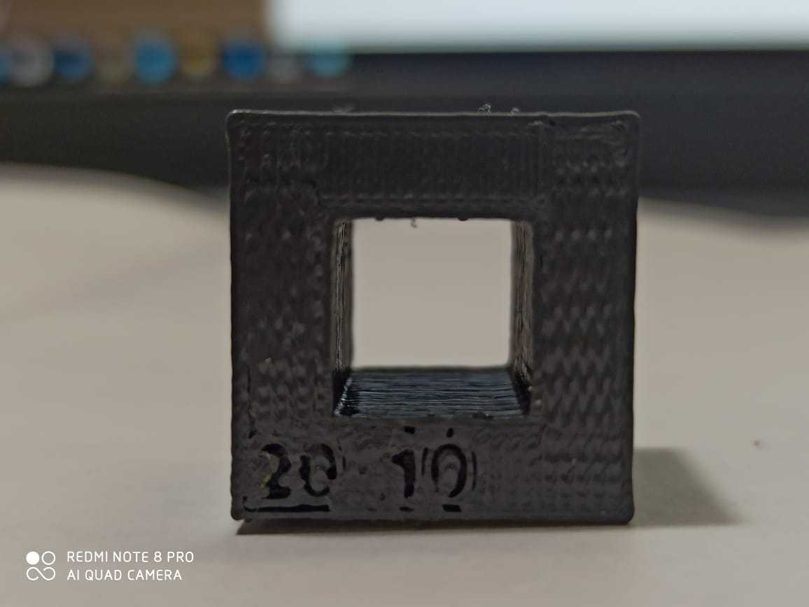
5. Wall thickness test
n manufacturing, you always want to use as little material as possible, or just as much as you need. This saves money, time, and meets specifications. Ideally, you should already begin considering such factors
at the drawing board. Then you can order the right amount of material to fit the job at hand.
This goes for 3D printing, as well. The added luxury is that you can decide the material thickness of your project’s walls, top, and bottom when you prepare the 3D print file for your 3D printer.
Here are some handy points to remember when deciding how to size your walls:
* Shell thickness: A good starting point is around 2 mm, but aim for a multiple of your nozzle width. Note that different slicers use different names for the walls. They could be called shells, perimeters,
vertical shells, outer shells, sides, or loops.
* Top and bottom layers: The 3D printed object usually looks best when using a multiple of your chosen layer height for the top and bottom layers. Typical numbers are anywhere between 5 and 7 layers.
* Top and bottom layer overlap: Often, there’s an overlap setting for the top and bottom layers. Use it to let the top and bottom print a bit into the walls for added connection and stability.
* Print order: Ensure that outer walls are printed first for better dimensional accuracy. (This comes at the cost of decreased overhang quality.)
Test conclusion
We found that the printer was able to build the wall till .4mm without string and .1mm minimum with strings over it. The holes were through till .4 mm and after that the holes could not be completed.
6. Dimensions test
Dimensional accuracy, as its name implies, is the accuracy of dimensions. we are going to specifically focus on the dimensional accuracy of 3D printed parts. How good is it? And how can you improve it?
But first, why is dimensional accuracy important?
In fact, for many models it is unimportant. If you just need something for fun or decoration, you usually won’t be pulling out the calipers to ensure a tolerance of 1 Angstrom. However, if you need precise
parts to be compatible with other hardware, for example, high dimensional accuracy is a must.
Before you start tightening belts and tweaking firmware, find out how accurately your printer is printing. To this end, a number of helpful test prints exist out there, with calibration cubes being especially
useful.
Using a specific example, Thingiverse user iDig3Dprinting’s calibration cube measures 20 mm in the X, Y, and Z directions. If you print it, you should measure the actual dimensions of your print. The
difference between the actual dimensions and 20 mm will equal the dimensional accuracy of every axis on your printer. (For precise measurements, use a caliper!)
For desktop FDM machines:
Greater than +/- 0.5 mm is BAD
Less than +/- 0.5 mm is AVERAGE
Less than +/- 0.2 mm is GOOD
Less than +/- 0.1 mm is FANTASTIC
Keep in mind that, most times, positive dimensional inaccuracies are better than negative ones. You can sand prints down to size, but it’s pretty hard to add material after printing
Test conclusion
The printed object after shrinking chnages its dimension. In our case the internal cavity redubes to 9.8mm and the outer cavity came out to be 19.74mm.
7. Anisotropy test
Anisotropy in dielectric properties can have deleterious effects in structures intended for use in high-field environments. We show that dielectric anisotropy is introduced into parts fabricated using additive manufacturing techniques based on the orientation in which the part is printed.
Test conclusion
The material property of the test part is going to be different in digfferent directions. it will be higher where the strans of the material are longitudnal and lesser where they are transverse.
8. Surface finish test
Ringing, sometimes known as ghosting or rippling, is when lines or features on a 3D print seem to repeat themselves across the surface of the model. It’s usually quite subtle, hence the term “ghosting”, but
can easily ruin the look of an otherwise excellent print.
Usually, 3D printer ringing artifacts will be focused around sharp corners of the model, like in the picture above.
What Causes Ringing?
Ringing is caused by vibrations. When moving parts, like the print head, change direction or speed, parts of the printer resonate, thus producing irregularities on the print’s surface.
Motion components
are not perfectly stiff or precise, and any sloppiness or flexibility will translate to vibrations and inaccuracies.
Is this Ringing?
Visible infill is sometimes mistaken for ringing. 3D prints consist of solid walls surrounding a sparse infill pattern, and if the print’s walls are not solid or thick enough, the infill may show through.
This, however, is not 3D printer ringing. The key to ringing is that it takes the shape of the model, like the X in the photo above, and “ripples” out instead of being consistent.
Test conclusion
The surface finish in the test piece is a function of the angle and overhang. In the test piece, where the angle is greater the finsh is good but as the angle of the depositon is decreasing the surafce finish is getting rough
9. Infill test
Infill is simply a repetitive structure used to take up space inside an otherwise empty 3D print. For the majority of prints, infill is hidden from view, but occasionally, special infill patterns are more than
worthy of showing off.
Of course, infill has other purposes. In addition to filling the empty space in a print, infill can also change it’s weight, depending on the material used. Furthermore, infill allows printers to print
flat horizontal edges over empty space reliably and efficiently. Without it, prints wouldn’t have much structure or stability, making them incredibly fragile.
Often overlooked, infill is perhaps one of the most important factors in 3D printing, and a rather variable one at that. With numerous patterns, densities, styles, and orientations, optimizing infill
can be a daunting task. However, with the right knowledge, customizing can be fun
Test conclusion
The strength and the density of the test piece will be higher and larger if the infill is higher and it will be lower if the infill is lesser.
10. Clearence test
3D printing tolerances are important when you create parts that must fit together. In particular, with FDM 3D printing, you need to watch out because tolerances tend to be loose.
If you have an idea of your printer’s tolerances, you can design parts with proper clearances in mind. Parts should be created with enough space between them to account for potential dimensional deviations.
Poor understanding of your 3D printer’s tolerances can cause parts to fit poorly or support structures to fully adhere to your prints.
Now that we understand why tolerances are important, let’s dive into how to test and improve your printer’s limits.
Test conclusion
. We found that the clearence at which the movement is smooth is .5mm and after that the motion stops. It is due to the shrinkage of the material.
FOR MORE INFORMATION REGARDING THESE TEST YOU CAN GO TO SITE THEY HAVE ALL THE INFORMATION REGARDING TEST AND HOW TO IMPROVE THE WORKING OF YOUR MACHINE (HIGHLY RECOMMENDED)
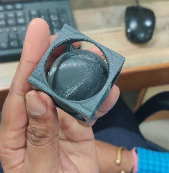
Individual Assignment:
For individual assignment i have designed a very simple Ball in the box object , as for this week the assignment was to make something which cannot be made using any conventional or subtractive manufacturing
And what i have designed cant be made by any conventional method as conventional method can only work for the objects which have only have geometry upro 2.5D above that they cannot make objects and in my case
                                                 i have designed a ball in box geometry where ball can move freely so thats kind of impossible when we use subtrative manufacturing
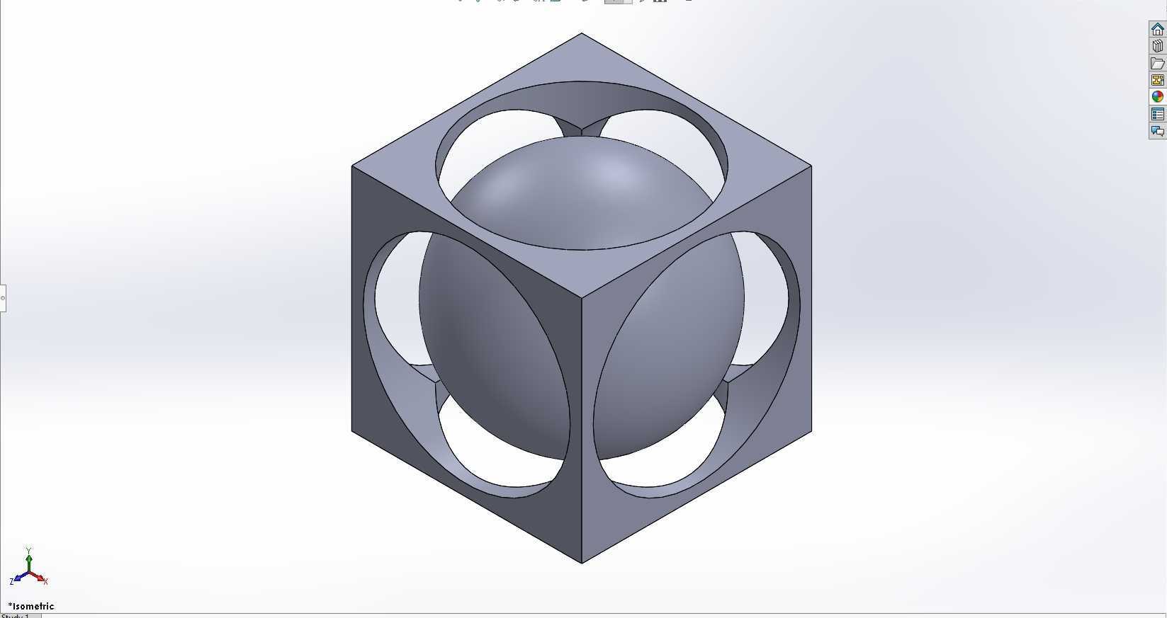
I made this in solidworks

I provided some clours to it so it looks cool
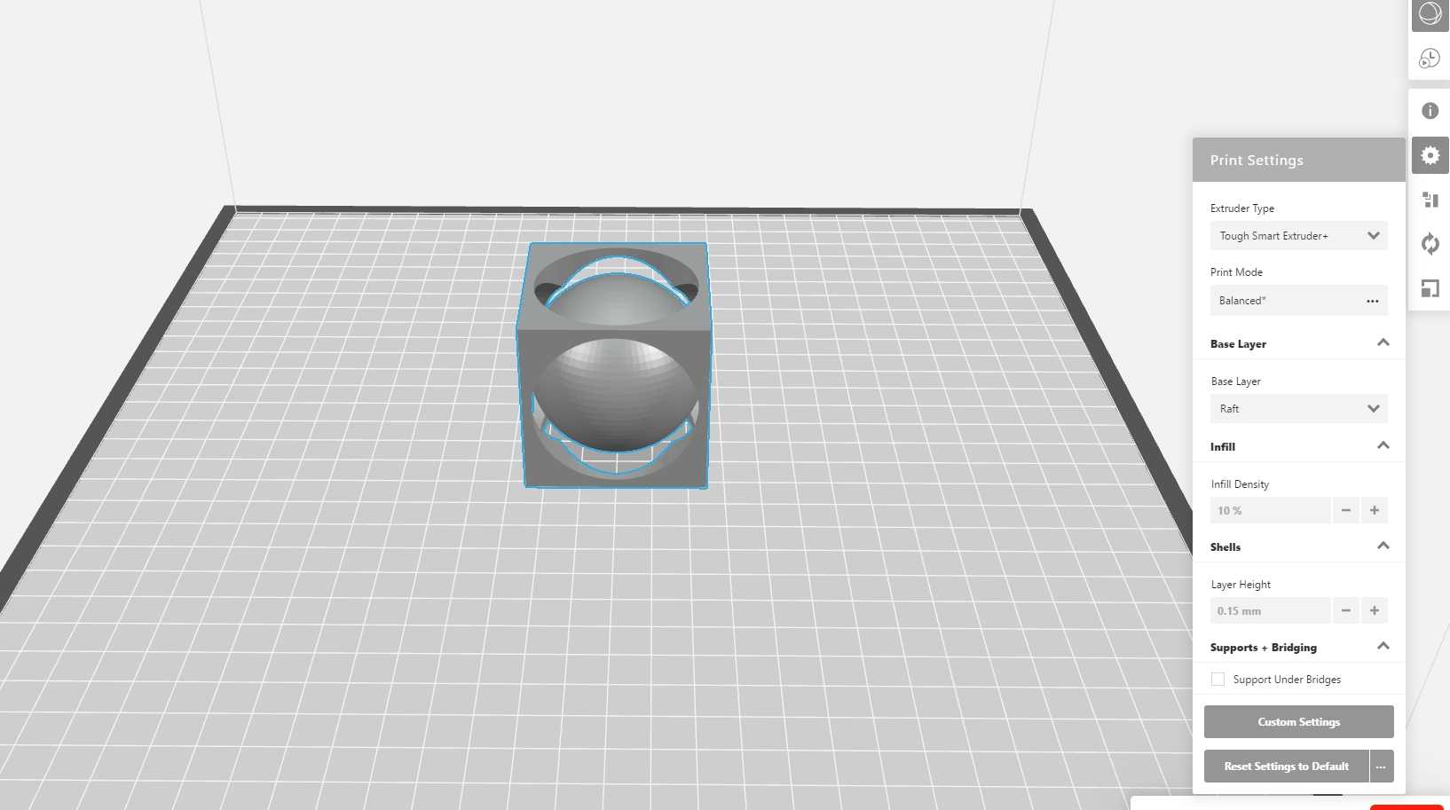
Then sliced it using MAKERBOT SLICER
Printing parrameters
Printing material : Tough PLA
Infill : 10%
Layer height: 0.15 mm Nozzle
temp :215 C
Support : no support

Then it shows 1hr22min of time for this to be constructed
And if you want to download the CAD editable file you can click on this link for that
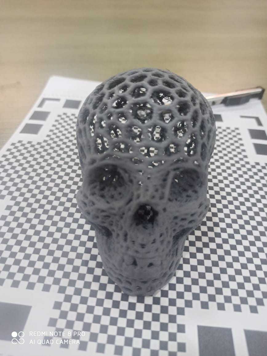
box and ballSkully
This was second thing which i printed on the 3D printer at our lab
I have downloaded this file from thingiverse and if you like you can go and also download it from this
MOTIVE OF DOWNLOADING IT IS TO PERFORM SAME POST PROCESSING METHOD
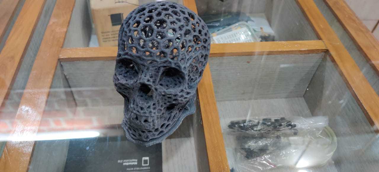
Printing parrameters
Printing material : Tough PLA
Infill : 50%
Layer height: 0.15 mm Nozzle
temp :215 C
Support : no support
POST PROCCESSING
STEPS FOR FINISHING
* 1. First clean the access thread;s due to printing defects and remove support and raft.
* 2. uae a fine sand paper (600 and above sand paper would be recommended) for finishing the surface
* 3. Spray primer on the object (recommende 2-3 base layer) and let it dry.
* 4. Apply the last coat of the paint.
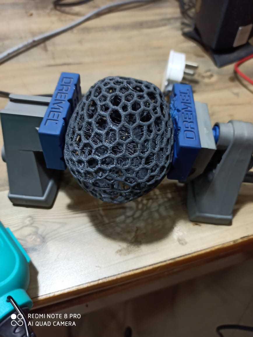
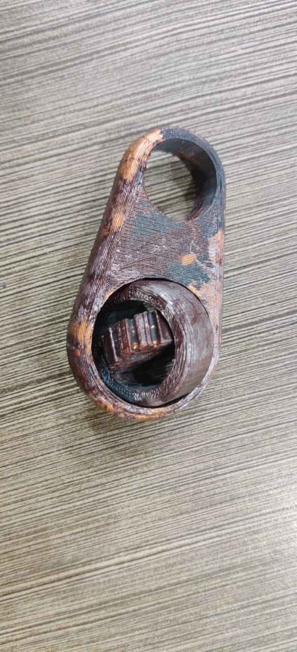
* The work piece have lots of threads due to some noxxle problem so i used Die Grinder
* This is a very usefull tool for cleaning and finishing of 3d printed parts.
* Applied 3 coats of grey primer and sanded it to make it fine
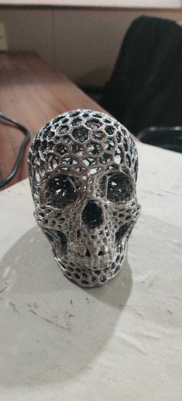
Applied 2 coats of chrome paint.
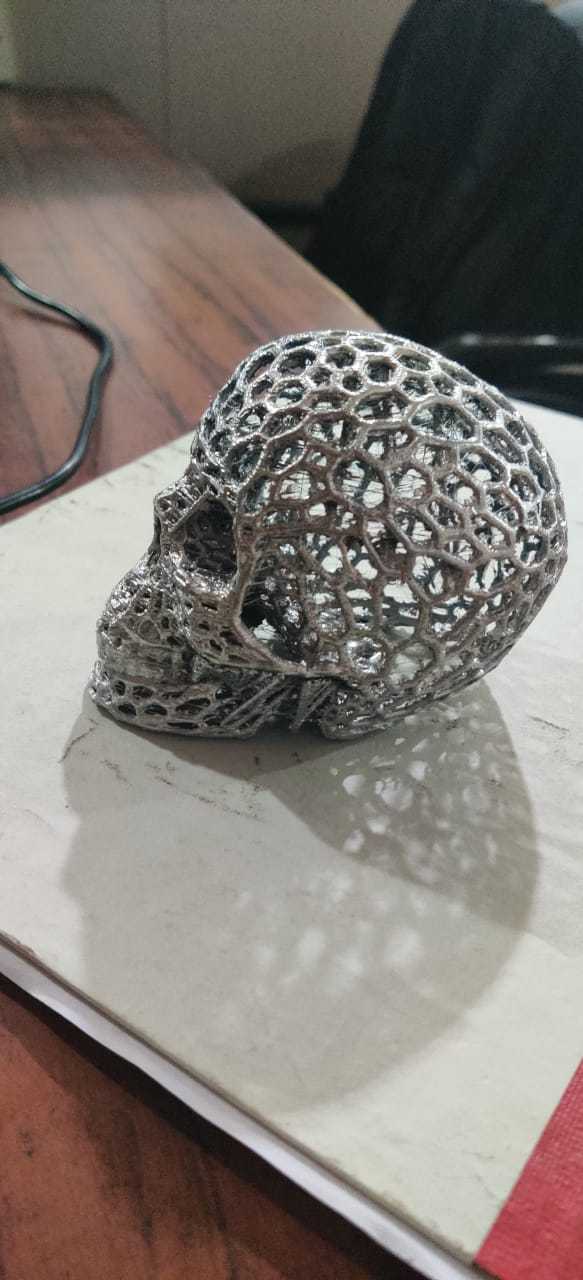
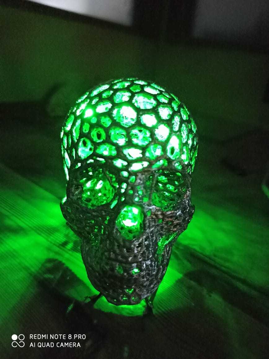
* I also added an Green LED strip with a 9V battery
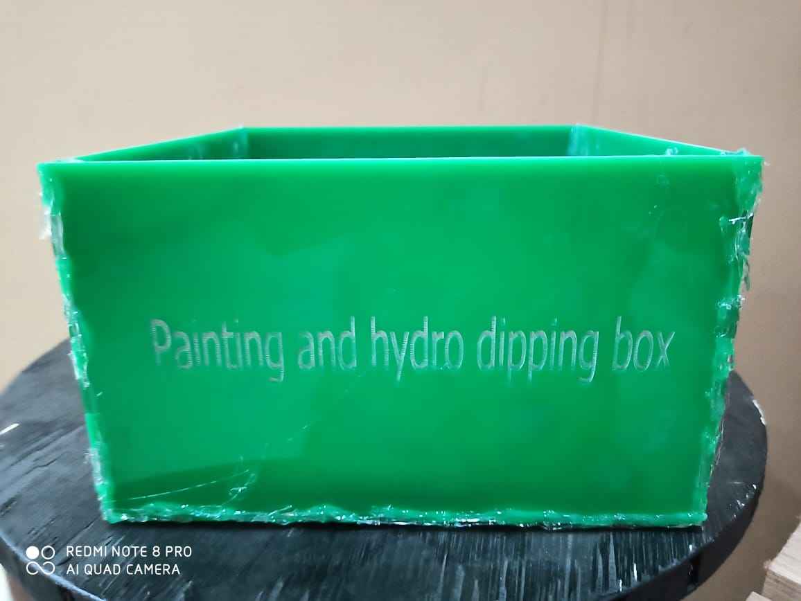
Hydro Dipping
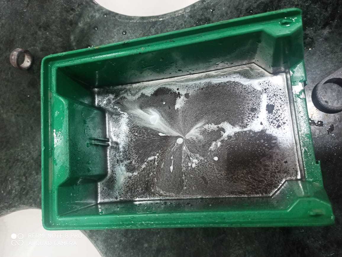
Water transfer printing, also known as immersion printing, water transfer imaging, hydro dipping, watermarbling, cubic printing, Hydrographics, or HydroGraphics, is a method of applying printed designs to three-dimensional surfaces. The resulting combinations may be considered decorative art or applied art. The hydrographic process can be used on metal, plastic, glass, hard woods, and various other materials.
Hydro dipping layer created by mixing chrome , gold and brown spray paint
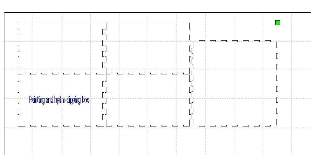
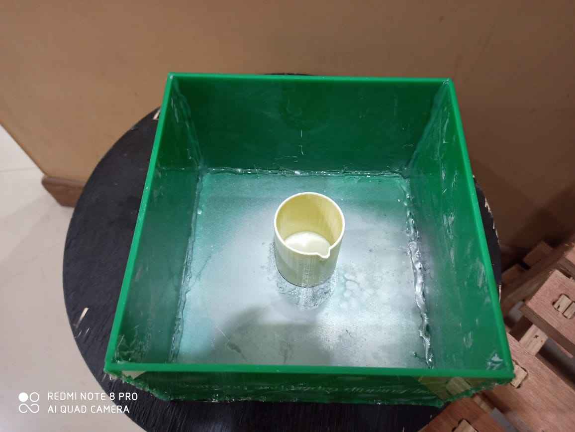
Due to absence of proper dipping bucket , i need to make a new one so i cutted an 4mm ACRYsheet for this.
3D scanning
So part of this week's assignment was to 3D scan something
QLONE

Qlone is a free mobile application which can scan anything using there software just by using a mobile phone's camera , if you like you can download this software using this link
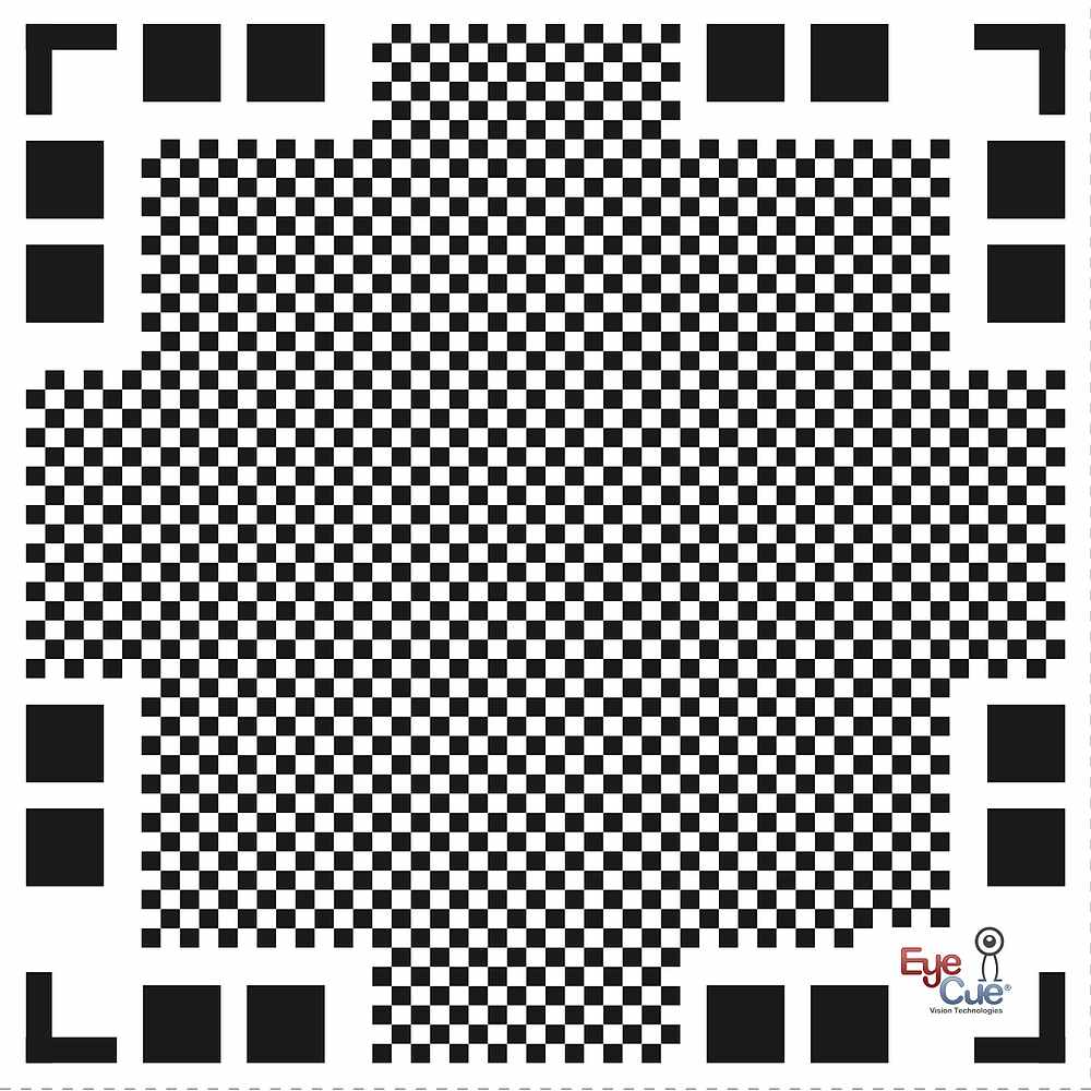
For scanning you required thisQr code like template and, when you install the software , this template is available in the app and you can easily download it , it have size of standard A4 paper
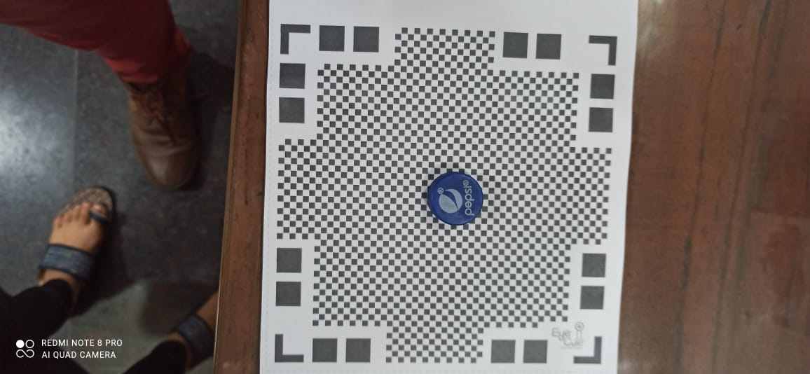
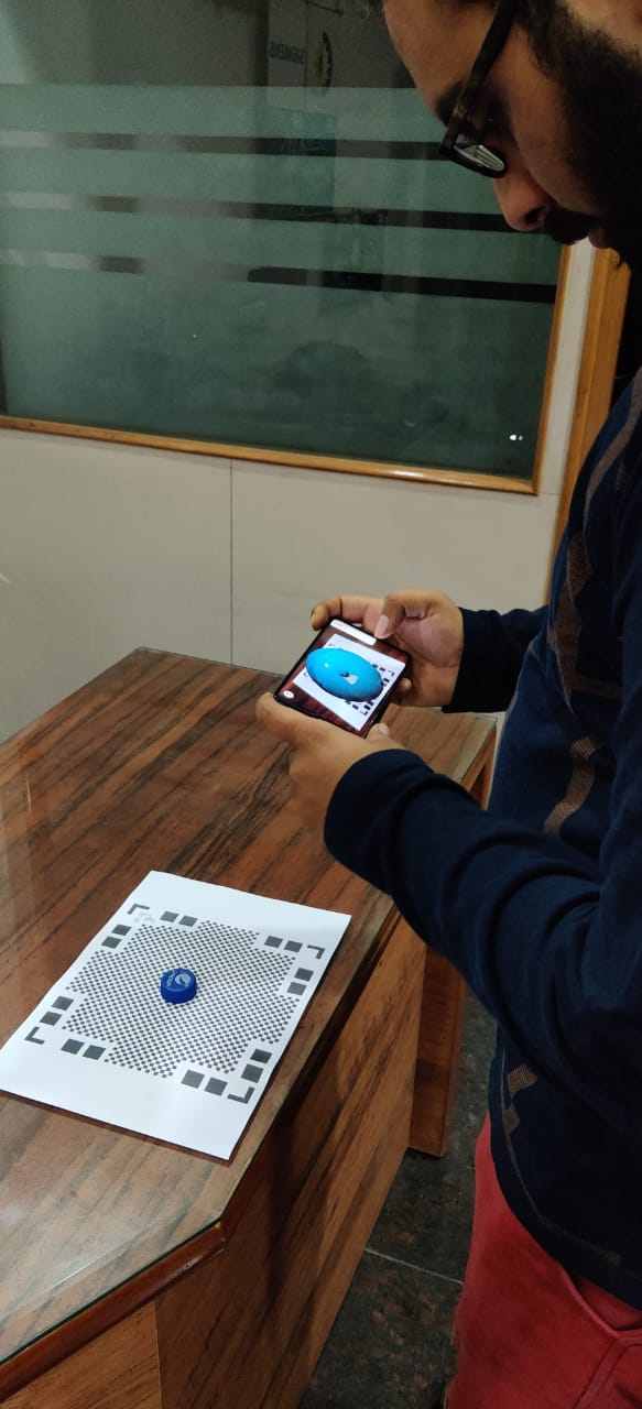
Initially i used this bottle cap to scan just for testing ,scanning procesure is as follow:
* Place some small object in the middle of that paper , like how i have place in the above image
* Then open the software in the mobile and point the camera toward this piece of paper and a dome will appear
* and to fully scan you require to rotate the phone or the piece of paper as we go through and you can see that buesish dome starts becoming transparent
*You require to do so untill all thedome become transparent
Something like this
The result for this experiment was not so good so i , decided to try it again
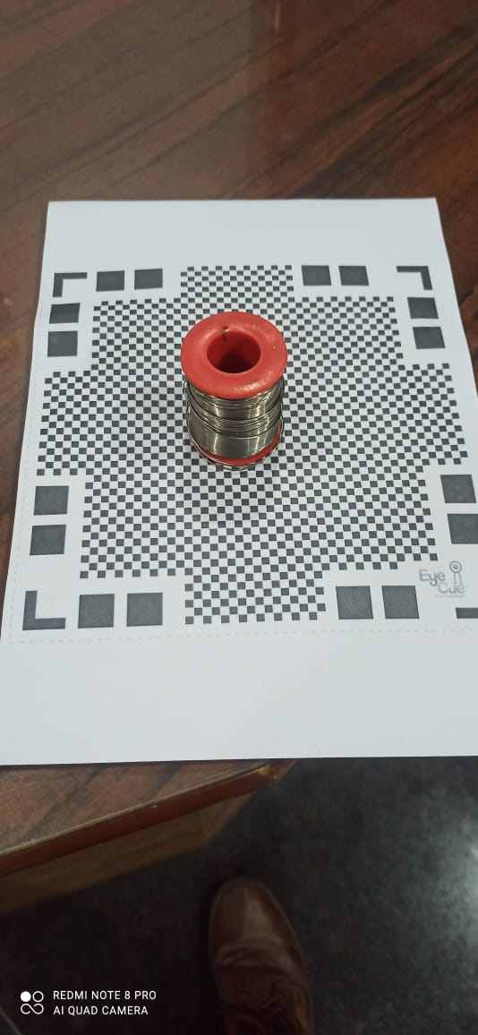
This time i choose soldering wire spool , this object is much better as it has some height to it and have a little bit more feature to it
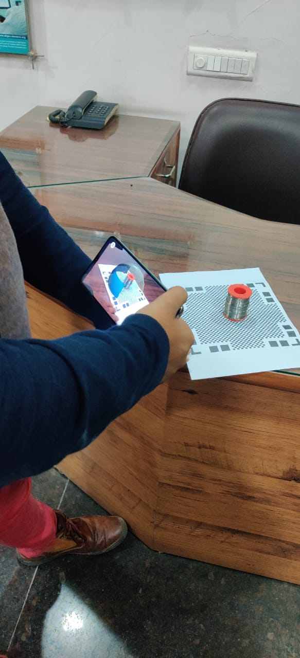
Here i am scanning it
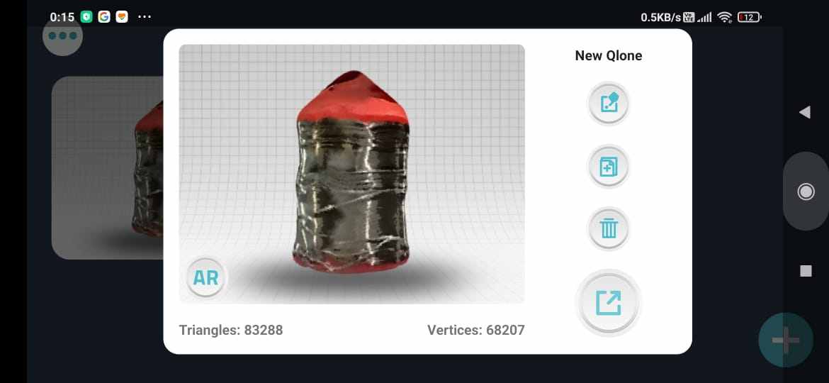
Once you have completed thescanning the software will ask to share what we have scan , but not give us stl only MP4 or GIF
Video for the soldering iron 3d scan , well it got some features right but some what , the results are acceptable