About us
We worked together on most tasks of this assignment. However, there were some separated tasks: David handled completely the design and fabrication of the 3D mounts of the machine, and Tue worked on this group website, plus the design and fabrication of the extra PCB.
Machine design and fabrication
Concept
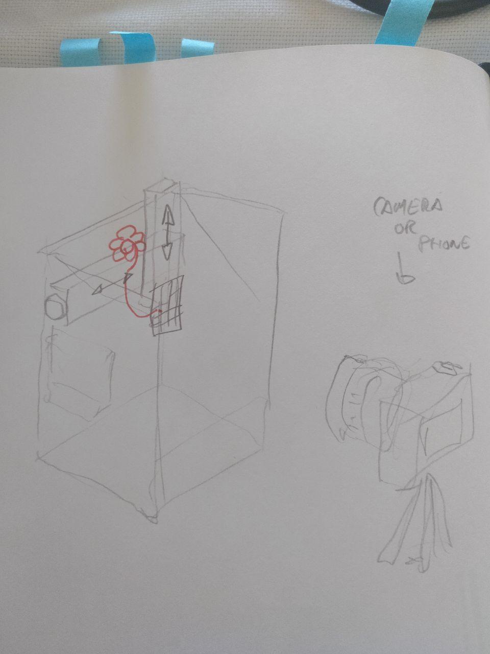
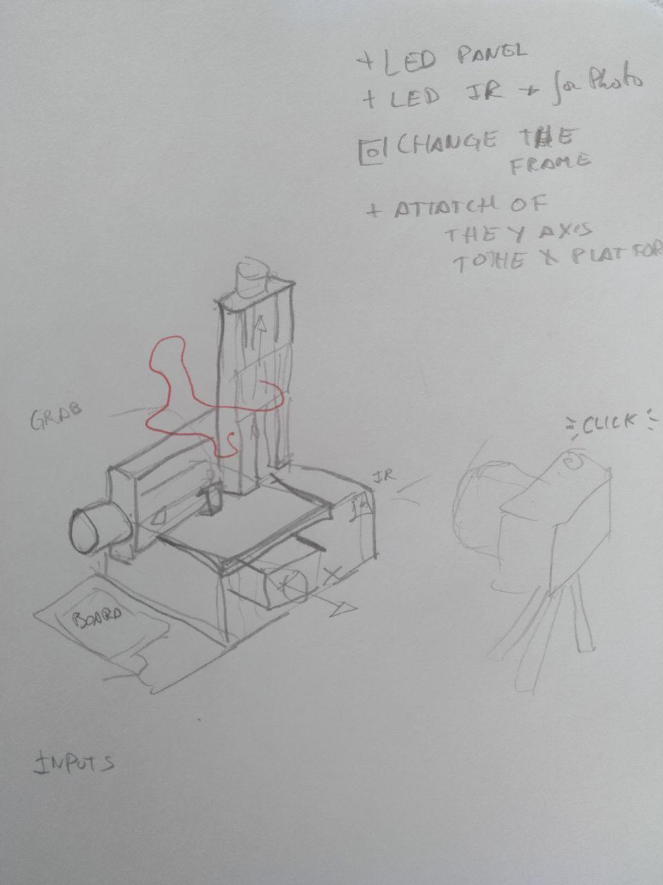
Our idea was to build a 3D light-painting machine that can move and paint with an LED so that later the whole movement can be captured with a camera. We planned to leverage the Barduino 2.0 board and its CNC shield, with some customizations.
Below are some original sketchs of the machine:
Understanding the SPML
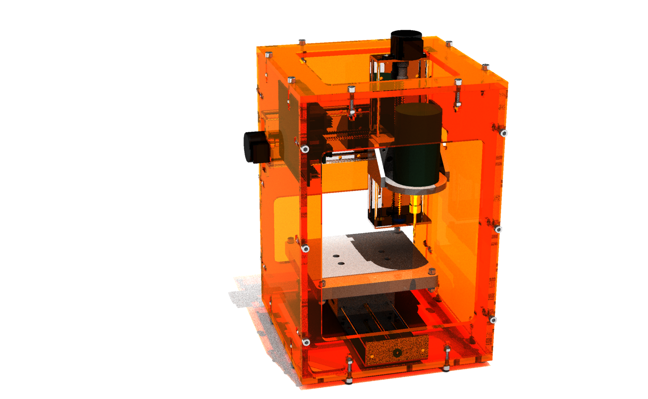
This machine started as a project to make a Fab Academy kit machine to help the students develop their Fab Academy assignments during the COVID-19 confinement. Basically, it is a 3-axes machine with a tool work area of 100 x 100 x 80mm and an exterior footprint of 150 x 150 x 200mm that makes it really portable, lightweight, and extremely low cost. We had this git reppository to investigate everything about the SPML. The README file is really extensive and clarifying.
The electronic parts of the SPML include a Barduino 2.0 control board and its CNC shield to control the actuators. The machine uses GBRLESP32 firmware with a self-publish ESP3D-WebUI to control the machine through the browser via WiFi or Bluetooth.
The machine is Arduino-compatible, and we needed to include these libraries:
    http://arduino.esp8266.com/stable/package_esp8266com_index.json
    https://raw.githubusercontent.com/espressif/arduino-esp32/gh-pages/package_esp32_index.json
    https://dl.espressif.com/dl/package_esp32_index.json
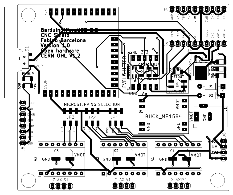
And this is how the CNC shield looks like:
Mounting the machine
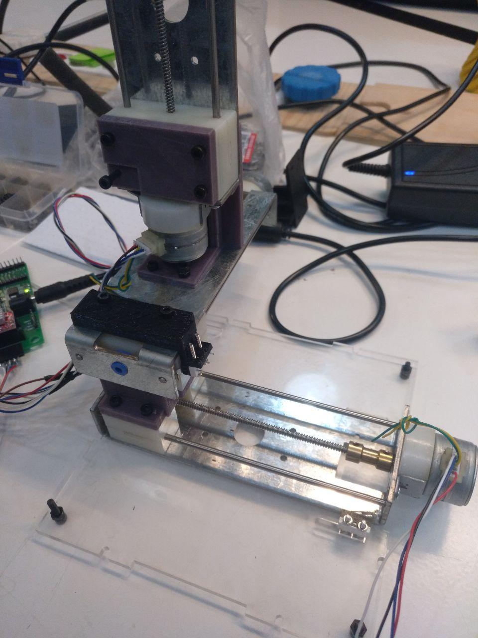
We took away all the laser-cut frames from the original SPML since moving a LED strip/panel doesn't require something as sturdy as if there is a spindle/tool. We kept the bottom platform because it had the X-home switch holder. We also re-designed all adapters for the Y-home switch, the Z-axis holder, and the LED panel/strip holder.
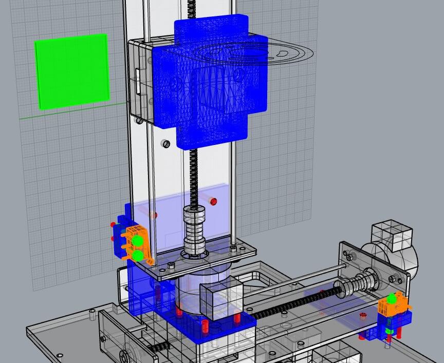
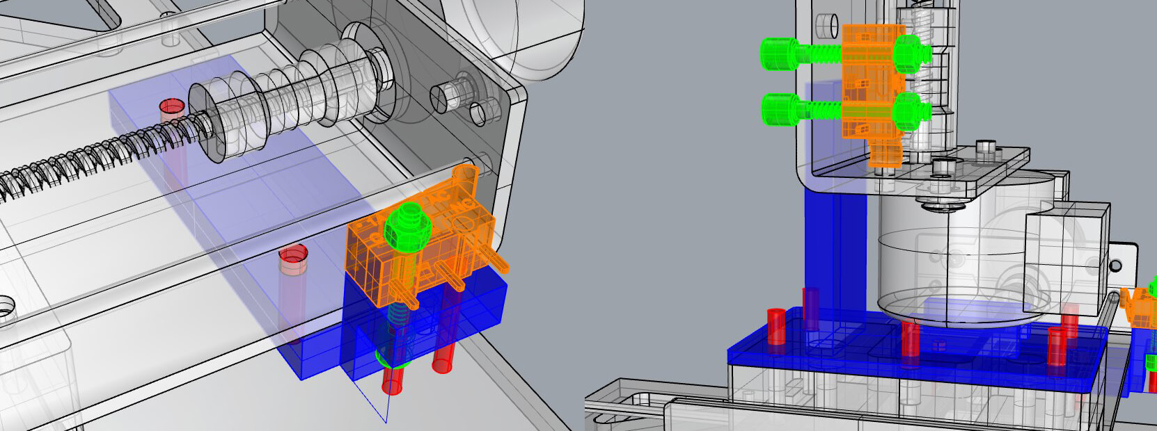
Once we has access to the lab, it’s time to get hands on and start 3D-printing the files to make the holders. Also we added an adapter to hold the extra PCB that was going to handle the LED.
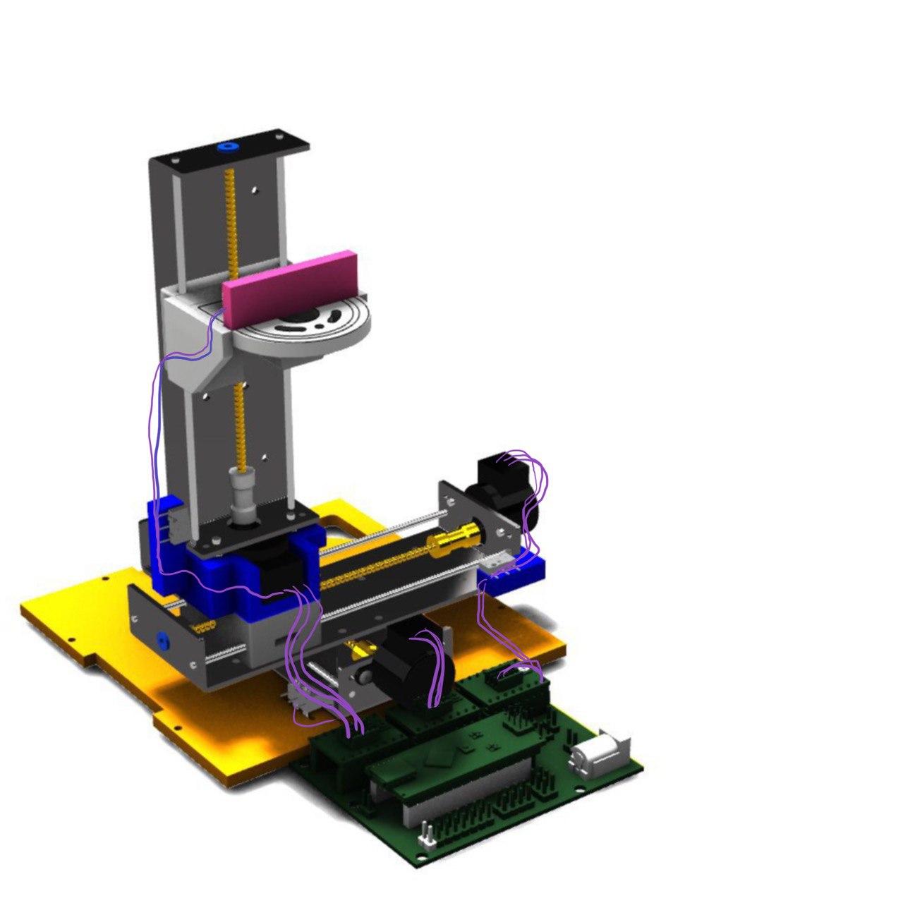
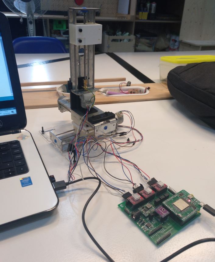
And this is how the machine got mounted:
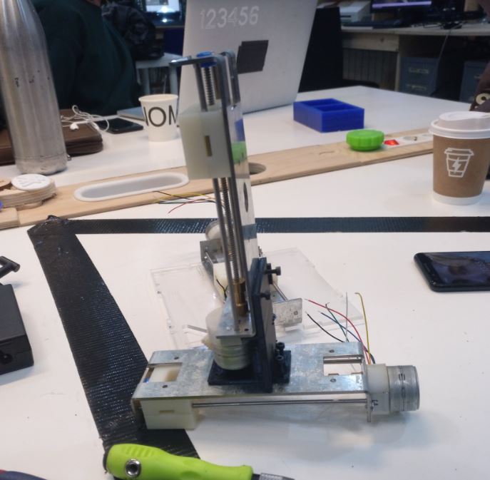
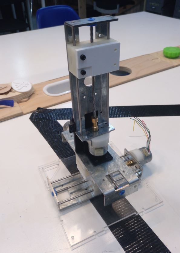
This was not an easy and comfortable task. The holes were too small so the screws had to be screwed twice to fit in and there were some tolerances in both measuring the distances and printing. Also, the X and Y connections were very difficult to screw because there is very little space for us to freely work on them. So we did it again later re-designing the correct pieces. And when we replaced them, it was much sturdier!
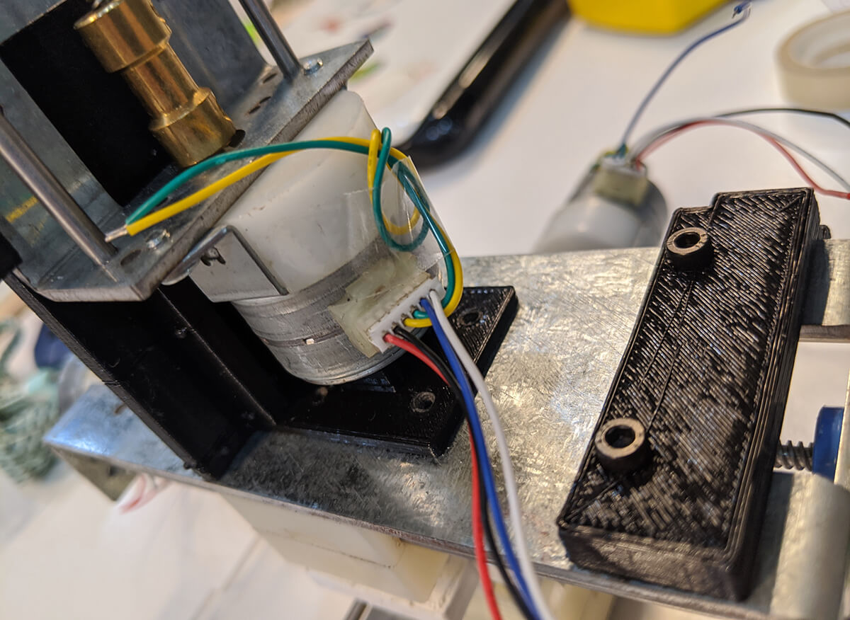
Making the connections
Now the most interesting part, with a lot of help from our classmate Arman. Basically, stepper motors are DC motors that move in discrete steps. They have multiple coils that are organized in groups called "phases". By energizing each phase in sequence, the motor will rotate, one step at a time. The number of steps per revolution ranges from 4 to 400. Commonly available step counts are 24, 48 and 200. Resolution is often expressed as degrees per step. A 1.8° motor is the same as a 200 step/revolution motor. Here we had 3 unipolar 6-wire motors for 3 axes, and 3 bipolar A4988 bipolar drivers, each with 4 pins. In order to solve that, we came up with a schema to understand how we should make the connections as below:
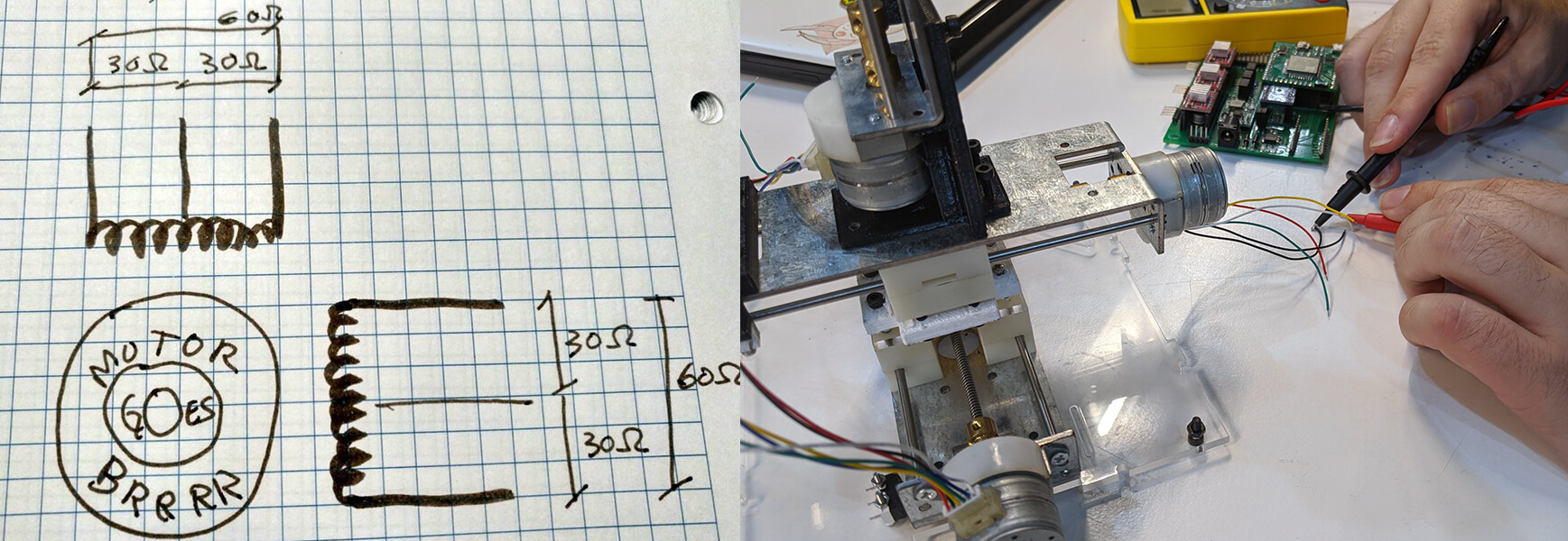
Speaking of the unipolar motors, they always energize the phases in the same way: the "common" lead will always be negative, the other lead will always be positive. The 6-wire motors only join the common wires of 2-paired phases. These 2 wires can be joined to create a 5-wire unipolar motor or we just can ignore them and treat the motors as bipolar ones. What we did was to go with the latter option and to measure the resistance between wires as shown in the schema. The wires that we connected were those that had 60Ω resistance between them.
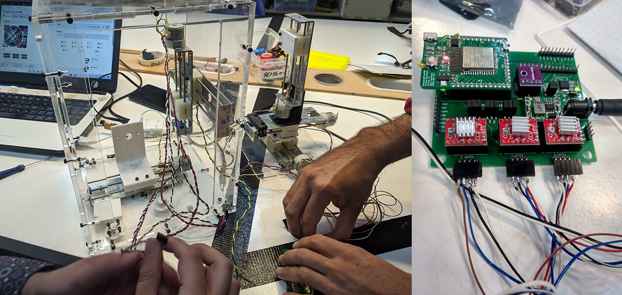
Working with GBRLESP32
Now we had the CNC shield and the Barduino ready:
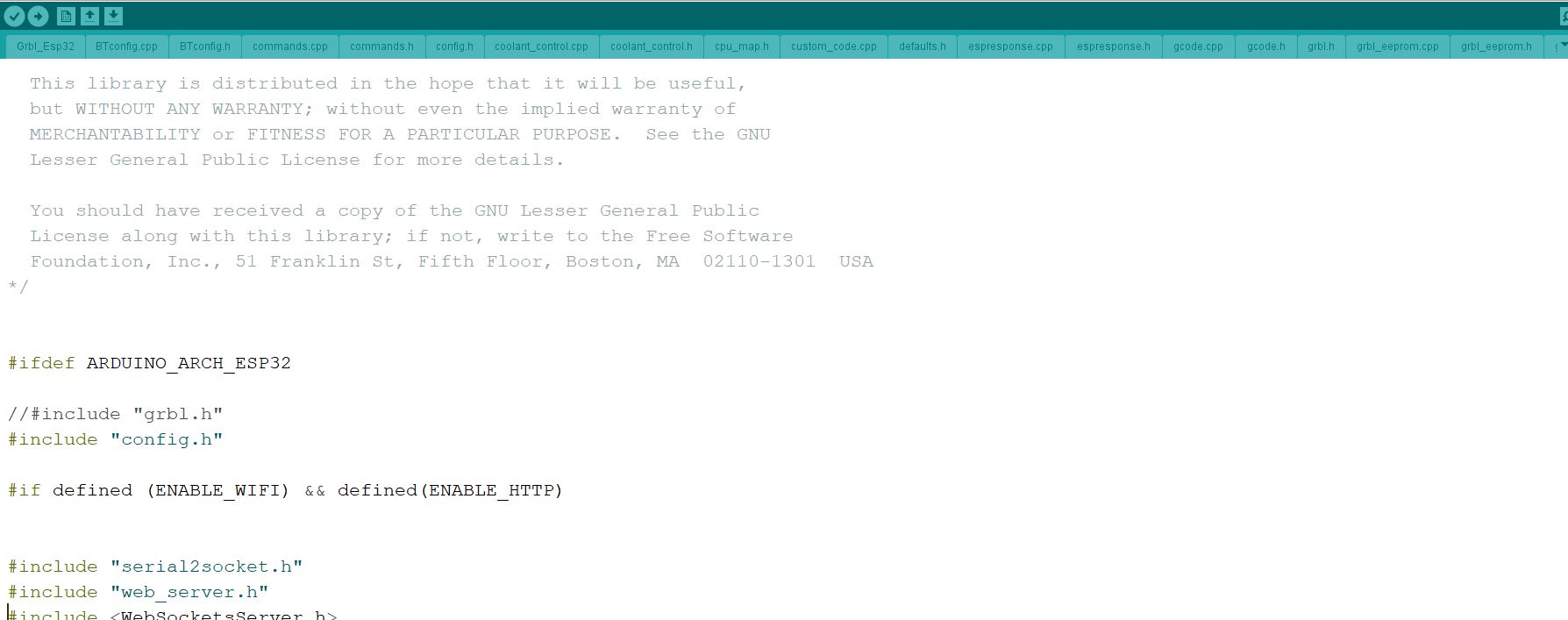
First, we had to download the whole firmware including all configuration files and the web interface here. We also needed to install all the necessary libraries and the index.html.gz file here. There are somany files included:
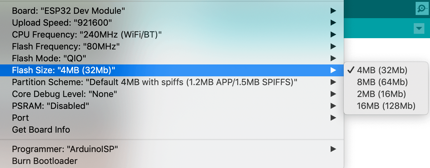
It took us a long while but we failed to flash the firmware to the ESP32 chip. The chip kept registering forever and ever. Later we figured out that we should choose the proper Flash Size:
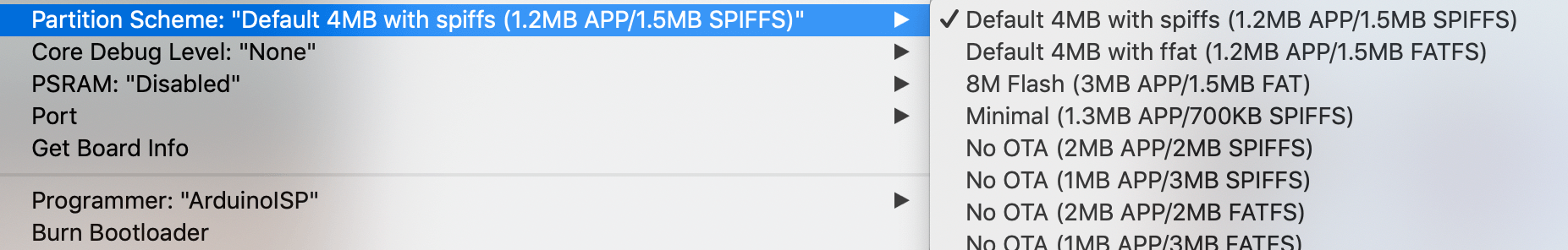
We also had to choose the Minimal SPIFFS option in the Partition Scheme section:
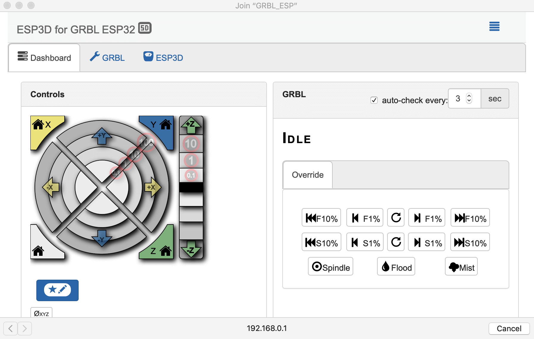
Finally, we could find a new visible WiFi in our PC with ESP_GRBL name, which means we had flashed our ESP correctly. In the web interface, we have 3 tabs. The most important one is the dashboard for sending commands, directly control the 3 axes, modifying feed and speed, and switch on/off some outputs (spindle, mist, or flood).
Controlling stepper motors
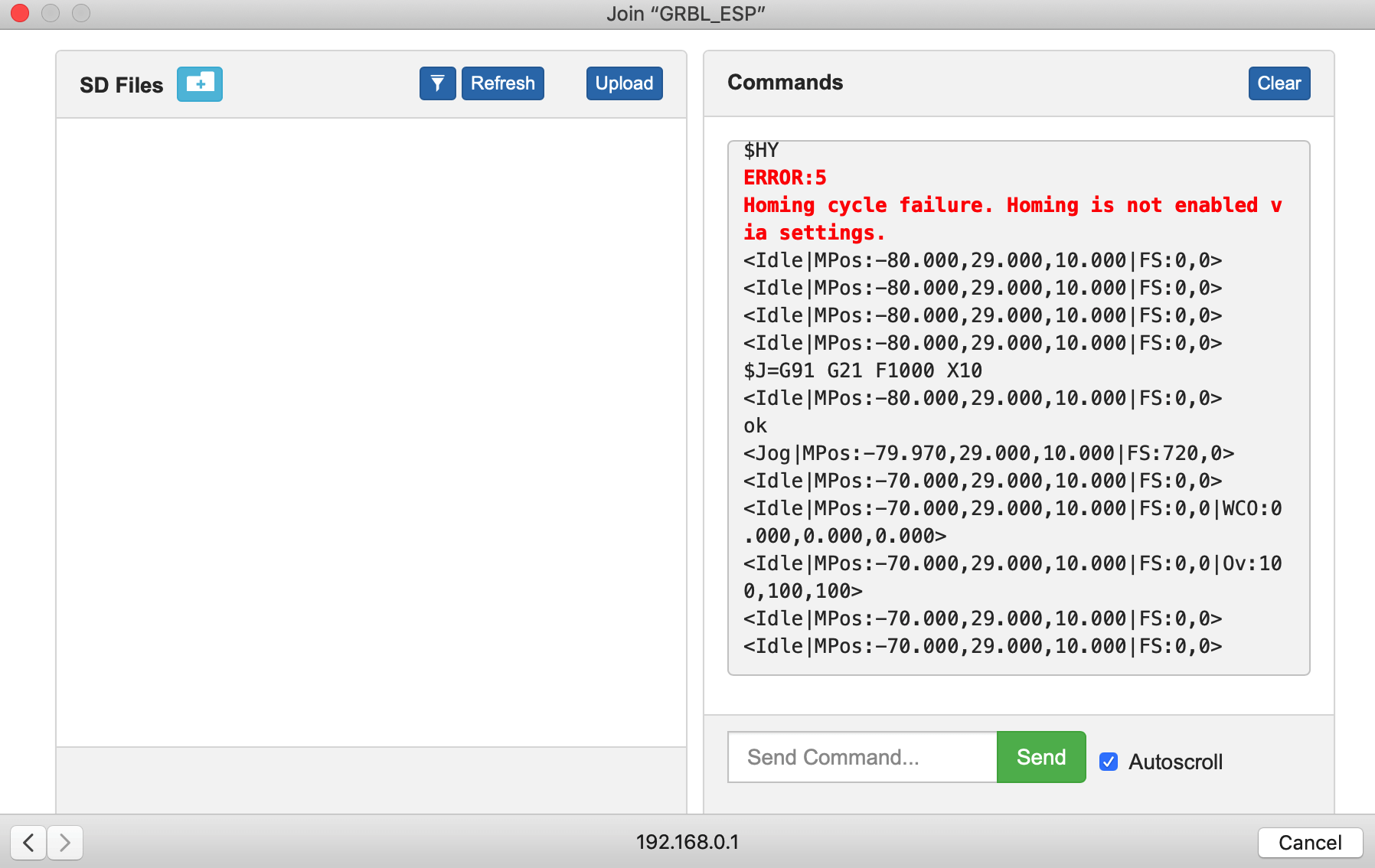
After being able to access the GBRLESP32 web interface, we tested the stepper motors. We had a problem right away that the motors were trying to rotate but got stuck:
To address this, we discussed with instructors Oscar and Eduardo and they suggested us to try these debugging steps:
- Oscar suggested us to check the regulated current of the stepper driver. We used the Polulu A4988 micro-stepping bipolar stepper motor driver that features adjustable current limiting, over-current and over-temperature protection. The maximum rated current that we should set the stepper driver to output is around 1.4 - 1.68A. This is important in order to provide the ideal amount of torque for the extruder to run without skipping steps or overheating and damaging the motor. In order to adjust the output current, we used a screwdriver.
- Since we could not measure current in parallel, Eduardo suggested us to check this reference in order to adjust the VREF instead. The formula used is VREF = maximum rated motor current x 8 x Rsense. In order to get an accurate result from the calculation we need to work out what resistors our A4988 used, and that number is Rsense=0.05Ω. So, the final VREF we wanted to adjust to was ~0.6A.
After adjusting the VREF (and thus, the regulated current), only the Z-axis was able to rotate and move perfectly, we still had problems with the X-axis and the Y-axis. We also tried to use our board and CNC shield to control the machine from our classmate Arman Narjari, and it worked. But it was not the case for our own machine. In the end, we decided to substitute the stepper drivers.
Yay! Finally! They moved as we wanted!
Controlling the LED
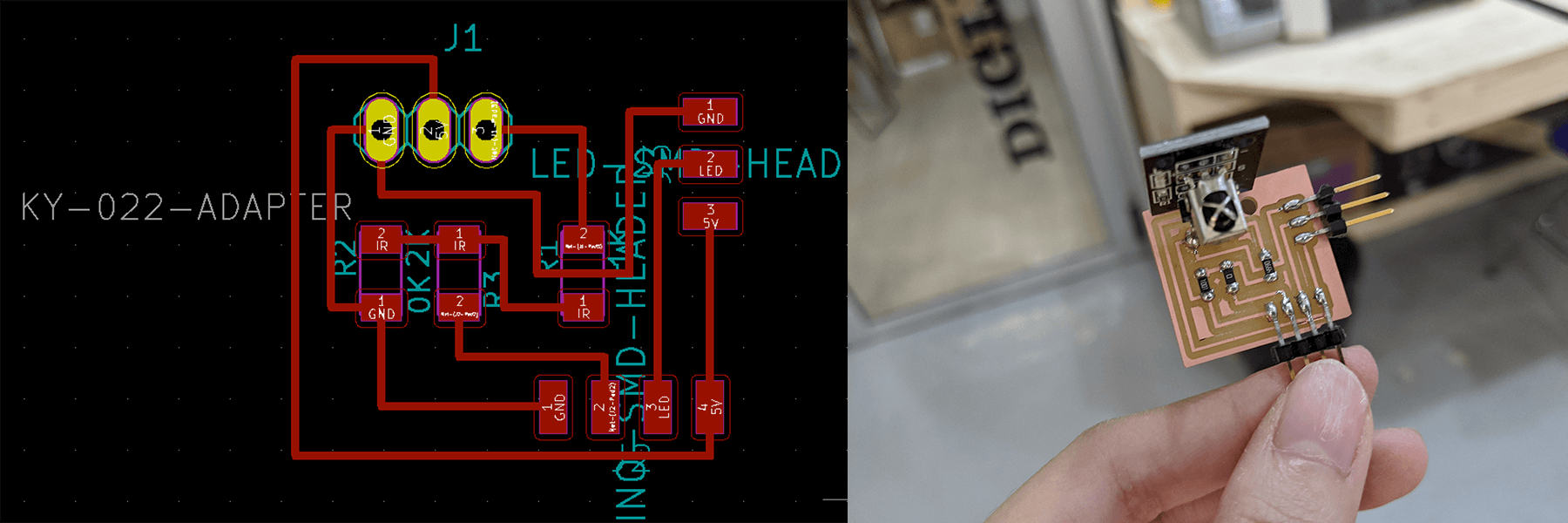
At first, we wanted to include an addressable LED strip for a fancier display of the light, and an IR receiver to receive signals from the camera. Here is the board I designed for those purposes, with pin headers connecting to the LED strip and the available input/output pins of the CNC shield (Flood, Mist, or Door):
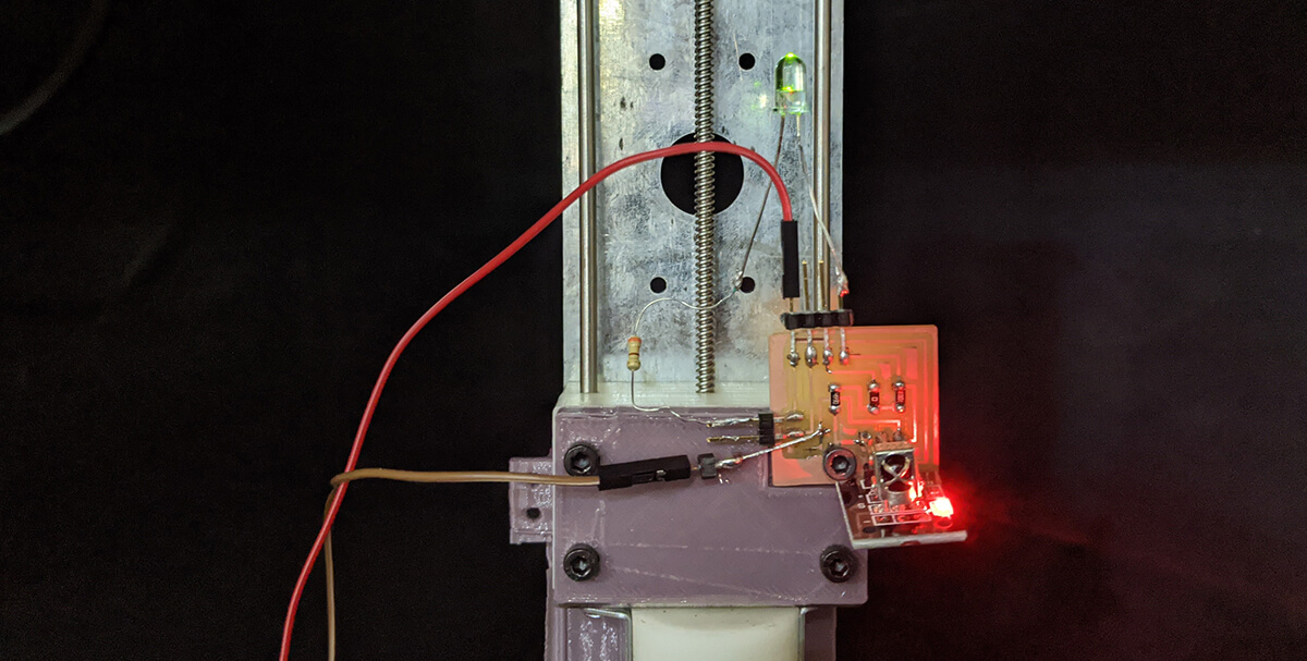
However, we were running out of time and we didn't want to work further on digesting how to send the correct data signal to the addressable LED strip. Therefore, we changed to a normal LED attached to the Spindle_PWM_3V3 pin and re-soldered the connections. So basically, we could simply turn on/off the LED with a certain brightness by sending M3/M5 commands with a certain spindle speed (a lot of assumptions were made here!!!). And fortunately, it worked!
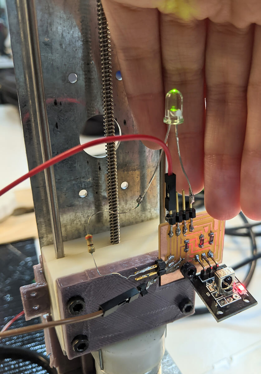
As per this reference, M3 is used to start the spindle turning clockwise, M4 is used to start the spindle turning counterclockwise, and M5 is used to stop the spindle from turning. In our case, M3 is used to turn on the LED, and M5 is used to turn off the LED.
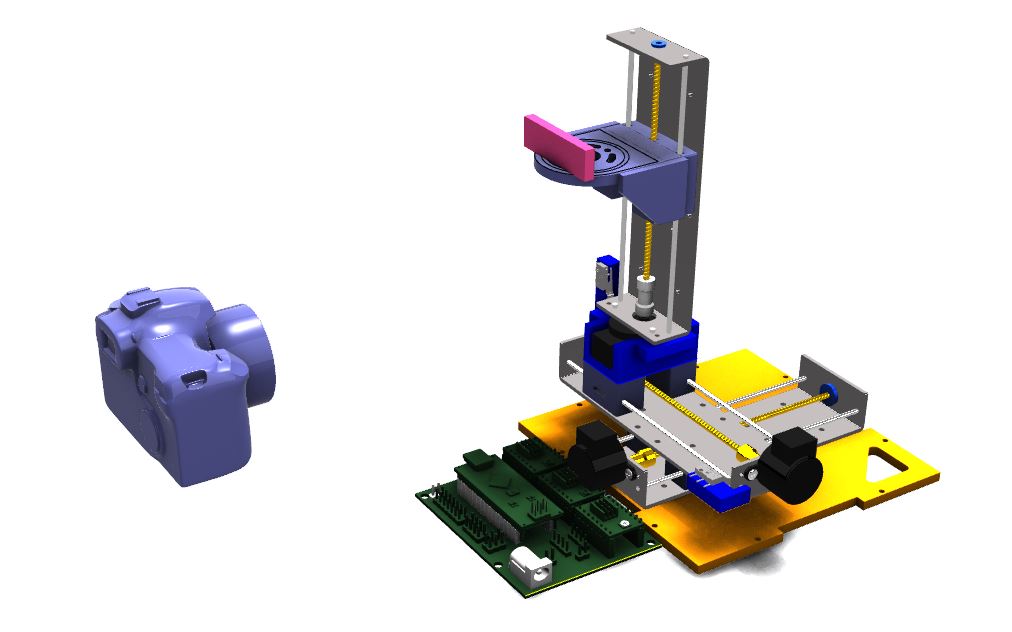
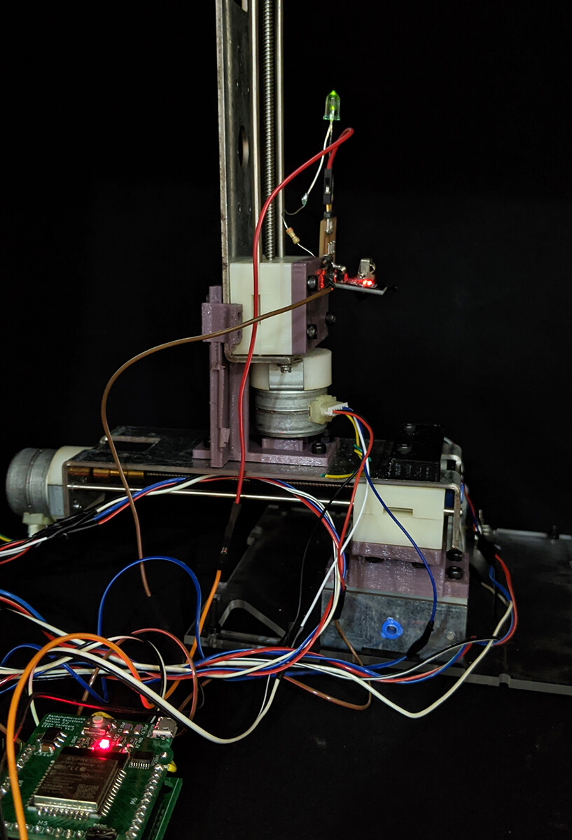
Here you go some hero shots of the final machine. It looks a bit like a Frankenstein-style machine, but it works!
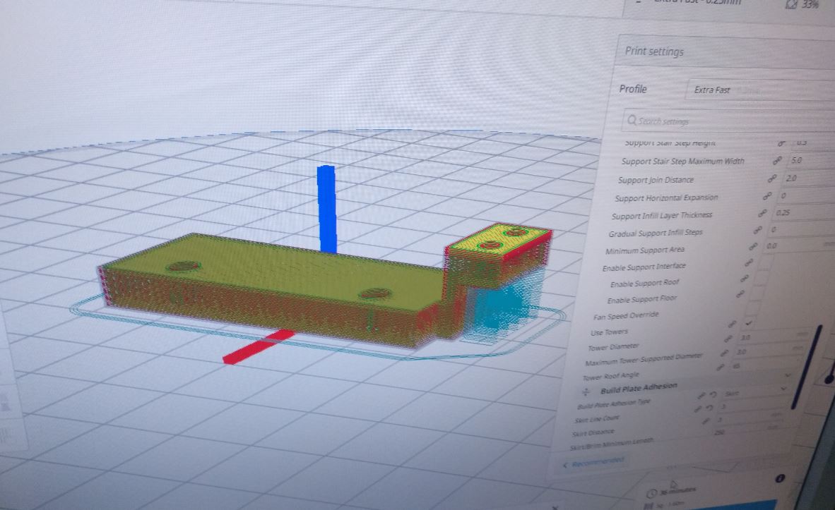
Generating G-CODE with Cura
In order to test the machine, first, we made a specific fake 3D printer resembling our light-painting machine with some below settings:
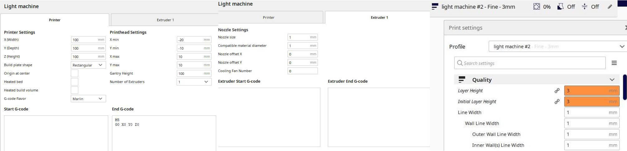
The M5 G0 XO YO ZO end G-CODE means stopping the LED and go to X,Y,Z home. Then we sliced the model and saved the .gcode file. The next step was to modify that .gcode file to make sure of its compatibility with GBRLESP32 commands and our machine. In summary, we had to make these modifications:
- Delete all the Fan-Off/Laser-Off commands:
M107 - Comment out all
Ex.xxcommands by adding a semicolon before:;Ex.xx - Add LED-On commands before every
G1commands:M3 S4000 - Add LED-Off commands before every
G0commands:M5
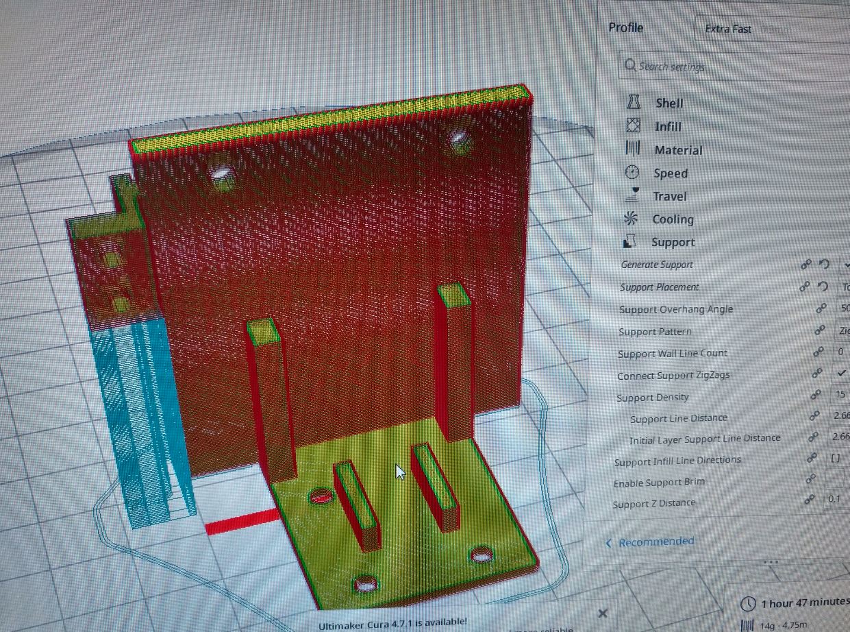
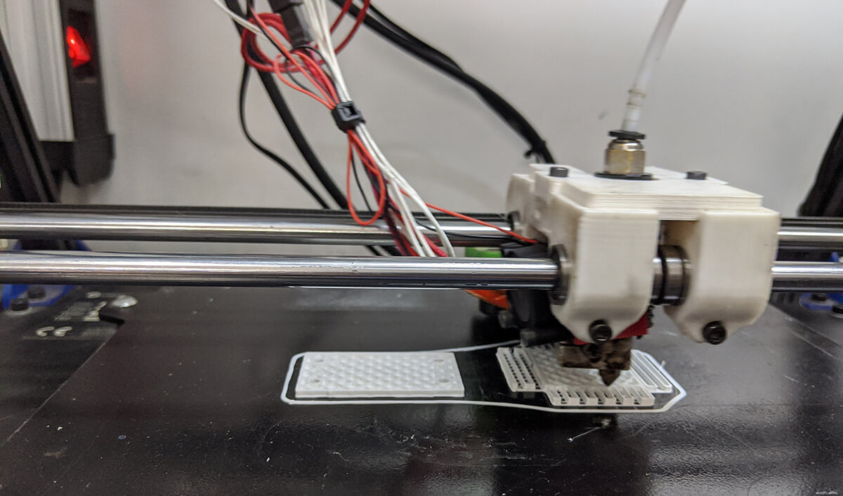
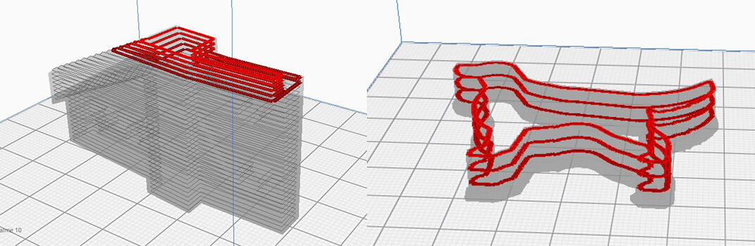
We repeated the above-mentioned process with 2 models: a joint from David's Final Project and a puppy:
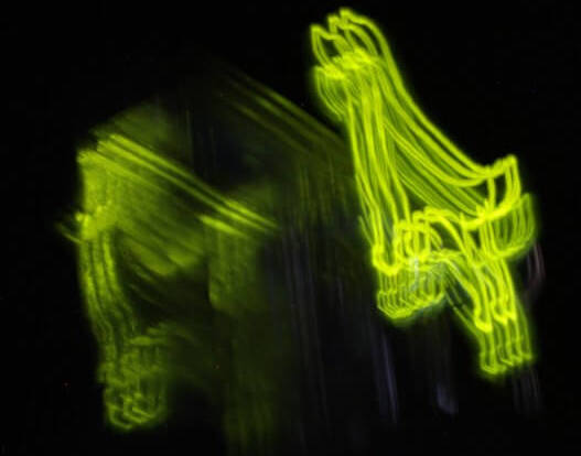
Capturing light movements
The process of taking the pictures was documented well here. We found a little space among the shelves in the lab with a completely black background and put dark cloths to make it even darker. Also, the camera (Canon EOS 450D) has 2 options for long exposure, either up to 30 seconds or as long as the button is pressed. Hence, instead of a one-take, we took multiple 30s shots and then combined them in Photoshop.
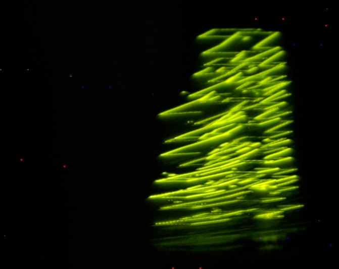
Wonderful, isn't it?
Conclusion and future works
It was an amazing experience for both of us to work on building a whole machine. For future development opportunities for this project, we could think of working on the original idea of a fancier machine with an addressable LED, and the machine could be automatically switched on through receiving IR signals.
Files
All readable and original editable files can be downloaded here.