3D scanning and printing
This week I worked on testing the design rules for our 3D printer, modeling and printing an object that can't be produced by subtractive process, 3D scanning and photogrammetry.
I also revisited a few of these test files so they can print faster and save on material.
Texts are engraved instead of being extruded out and are placed elsewhere, and the base of the meshes uses less material:
The new "Overhang" test file is a mix of the old "Angle" and "Overhang" files in one single test file.
You may download these new test files : Print_tests.zip
I used FreeCAD and made it parametric with the use of a spreadsheet.
Here is the FreeCAD file.
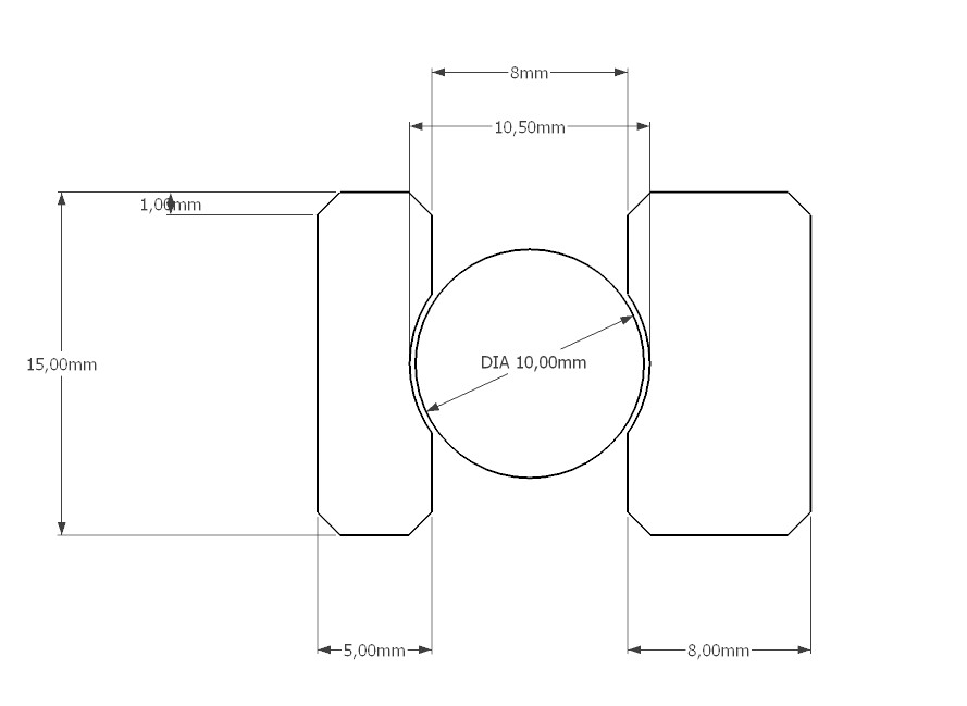
The spheres are 10.75mm in diameter, the clearance is 0.25mm and the axis diameter is 8mm.


Printing time was 2h12 and it was printed on a Creality CR10-S Pro.
This is a photo taken at mid print (50%):
The supports were easily removed by hand and the bearing is rotating freely. Here is a photo of the final print:
I also built a 3D scanner with a cheap webcam and a cheap laser emitting a green line. If I can find back photos and past work about it I'll add it here.
But that was something like 10 years ago or more...
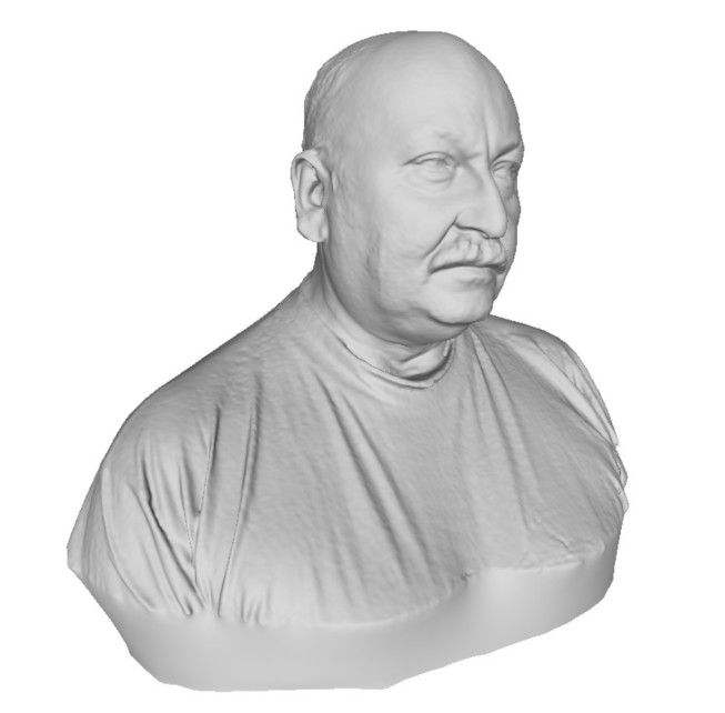
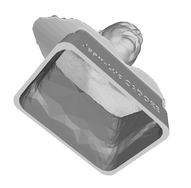
One of our colleague at work was retiring so I wanted to offer him a bust of himself.
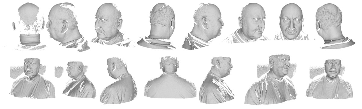
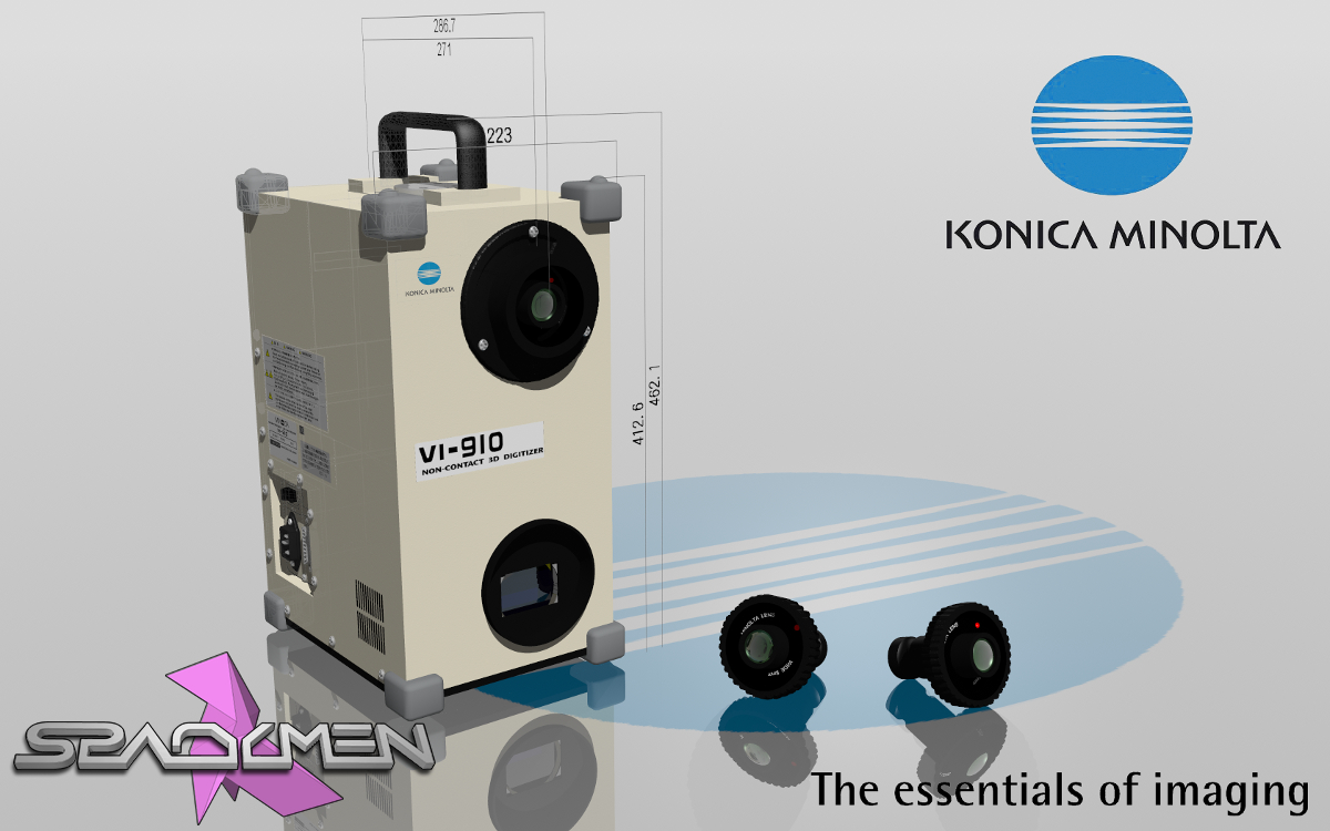
The scan process was made on an old Konica Minolta VI-910 and the individual scans were registered and fused using David software.
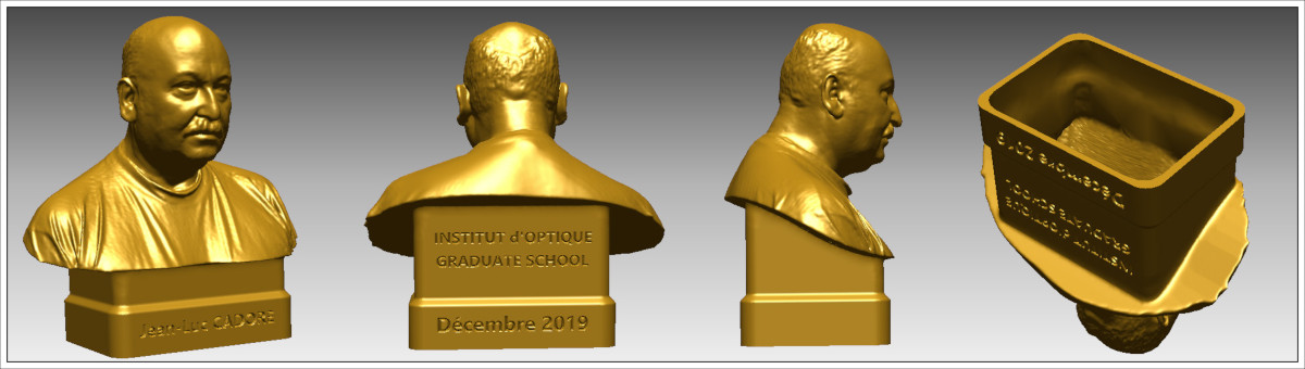
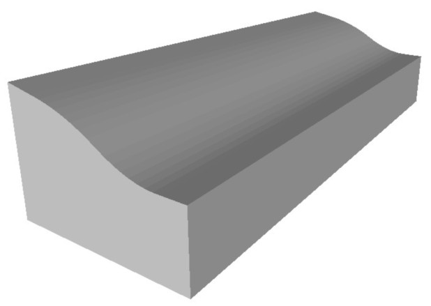
Then I modeled a block to be used as negative boolean and added a base with some engraved text on it then made it hollow with a 1.2mm wall thickness to later save on print time and material.
All these steps are performed in 3Dbuilder.
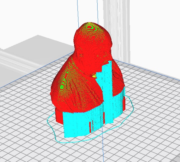
Slicing was done in Cura and printed on a Creality CR10-S Pro.
Finaly it was filled with plaster to make it heavier.
I tried to cover the subject and to make it understandable for anyone.
The fablab of our school is situated in a very old building that needs some repair.
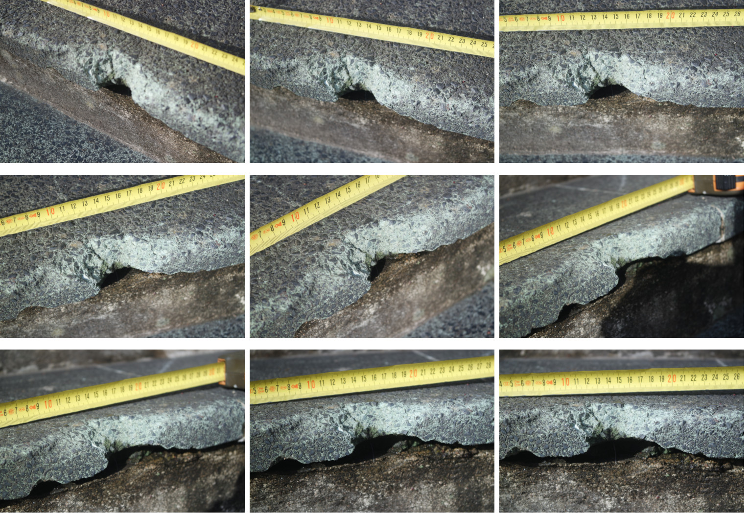
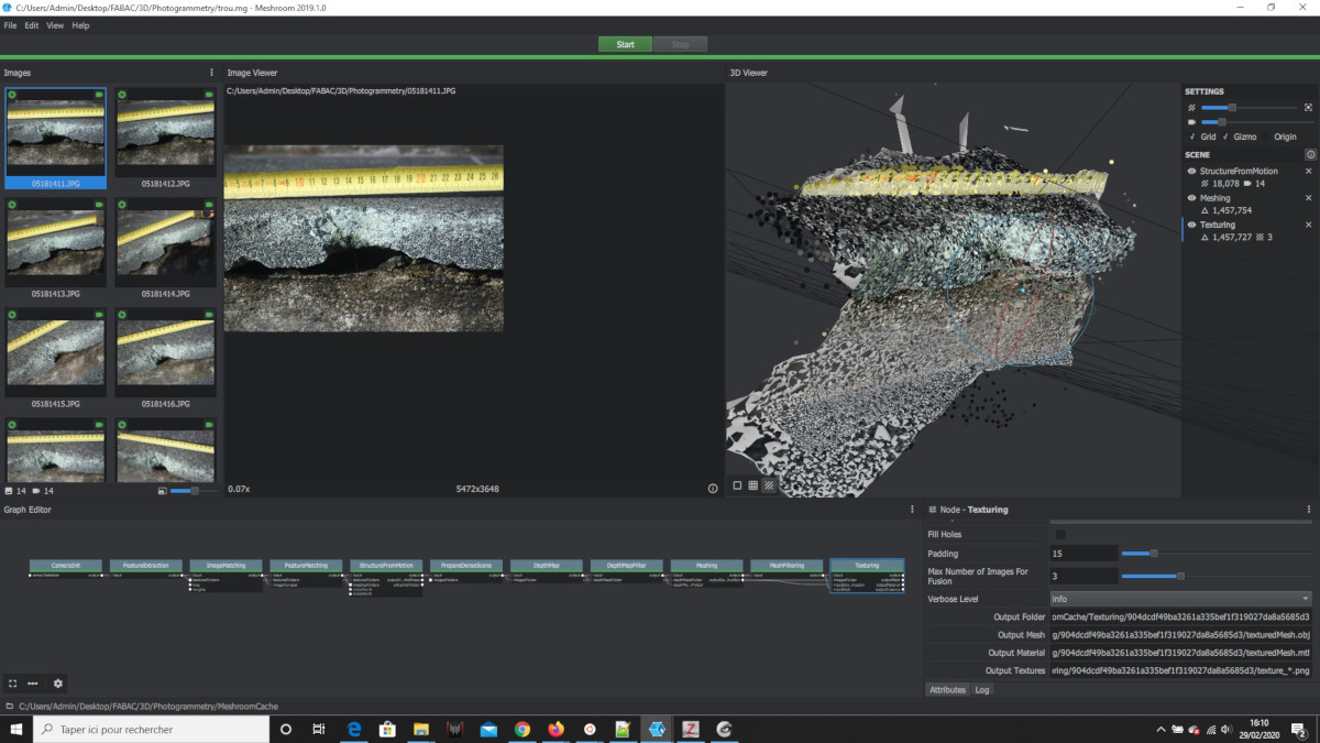
I took several photos of a broken part of the stairs at the entrance of the building and made a photogrammetry in Meshroom.
A ruler was included in the scene before shooting photos to be used as a reference for future scaling purpose.
The obtained mesh will be used later in the process as a subtractive boolean component.
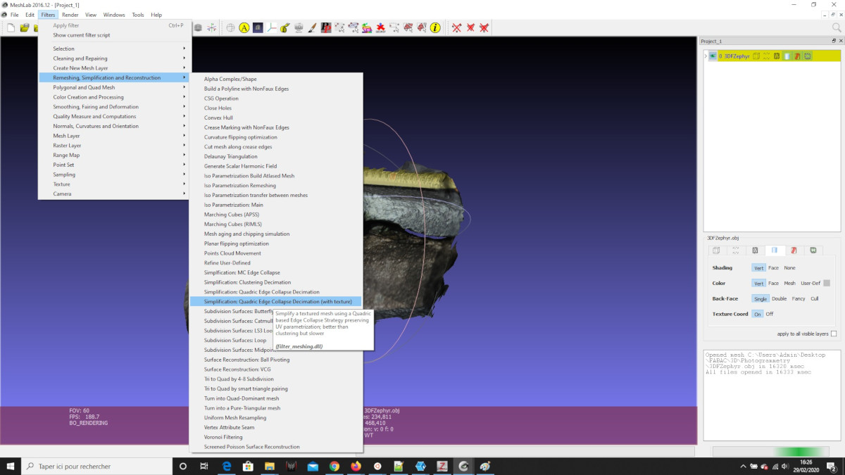
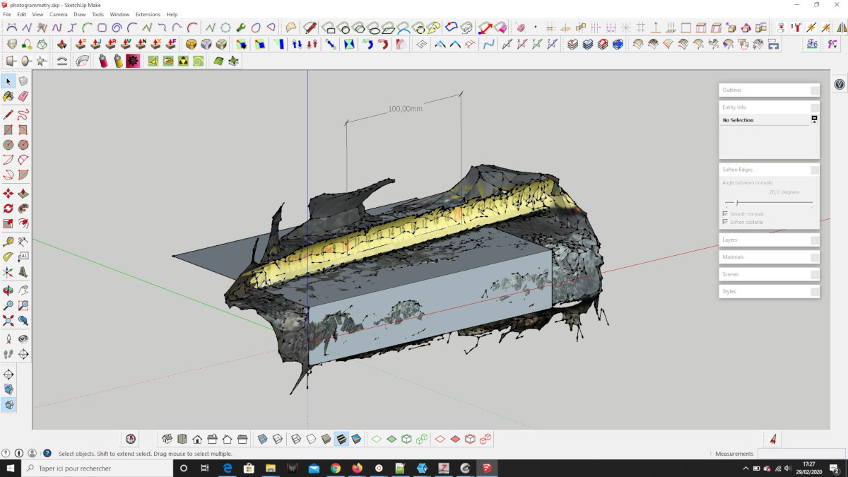
It was then decimated in Meshlab, exported back, and imported in SketchUp to be scaled to real size (with the help of the ruler seen in the photos), and reoriented to match the XYZ coordinate system.
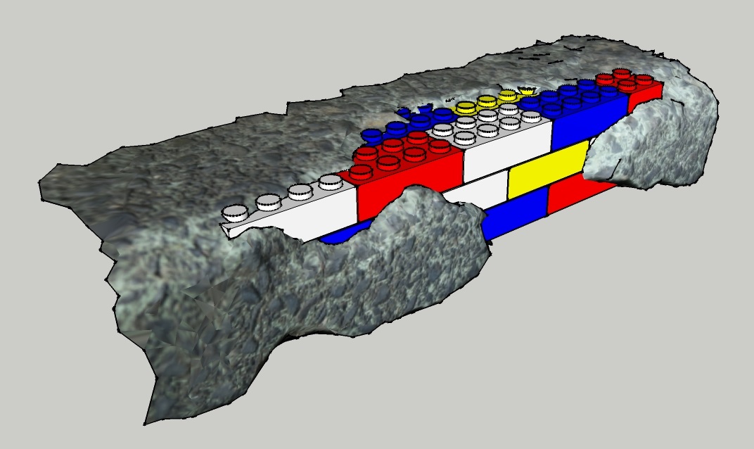
I wanted the repair to look colored and attractive by simulating Lego bricks being inside the concrete in a "trompe l'oeil" style.
So I designed a block simulating several assembled 4x2 Lego bricks, making sure to make it bigger than the damaged part.
The mesh obtained in the previous step (photogrammetry) was used to cut the Lego bricks by a boolean operation in 3Dbuilder, and exported back as STL for 3D printing.
This is how it should look like if everything went well:
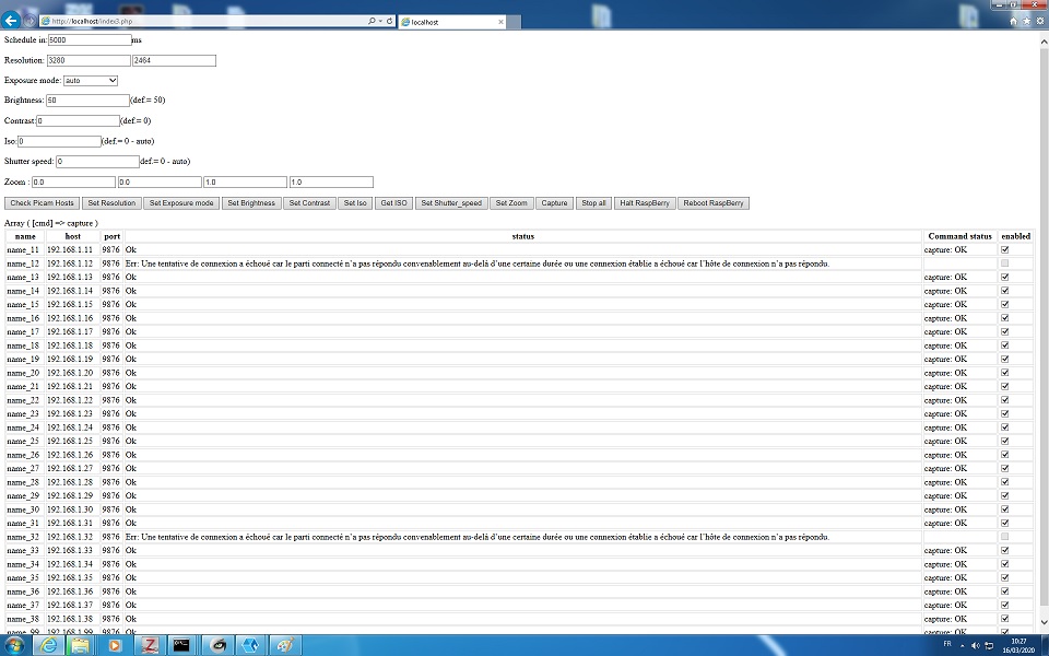
The best way to avoid this is by using a photogrammetry stage where all the photos are shot at the same time. In order to do that I built a small photogrammetry stage consisting of 24 RaspberryPi equiped with Picam connected by network.
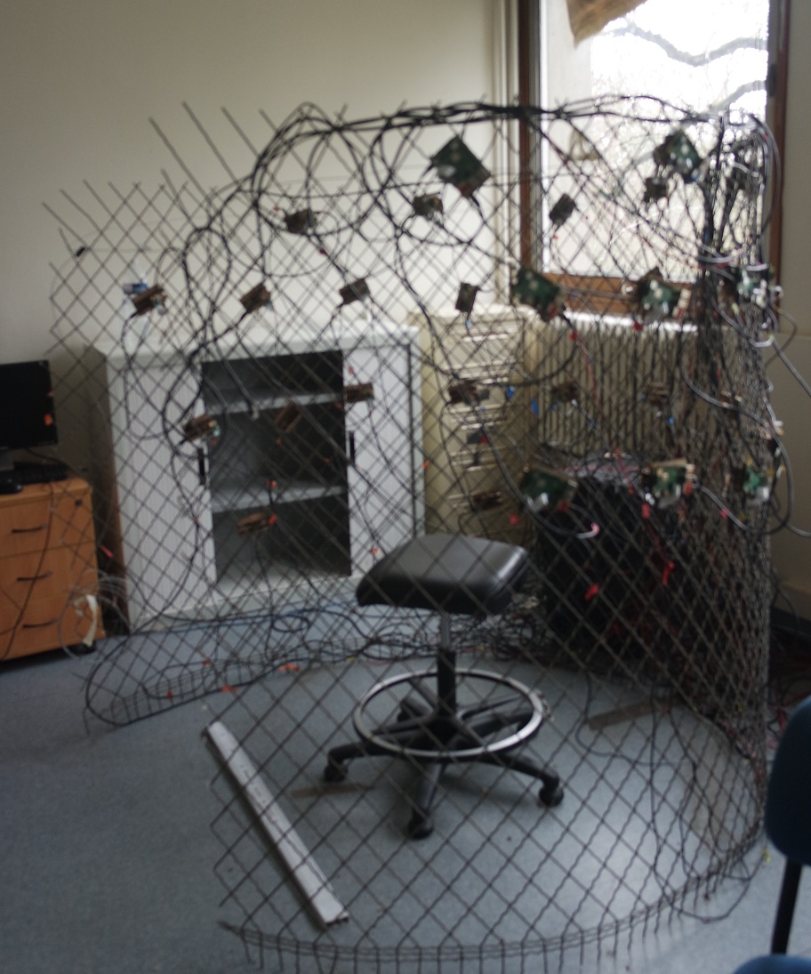
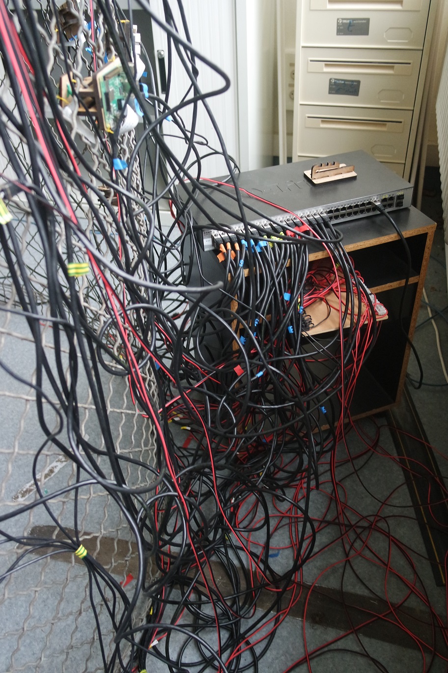
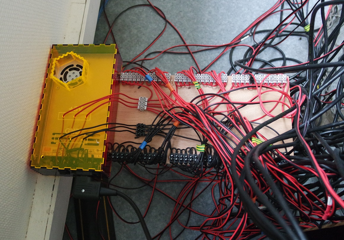
Only 24 RaspberryPi but already a lot of cables:
A home-made program (Python/PHP) synchronizes the RaspberryPi in order to trigger all the Picams at once.
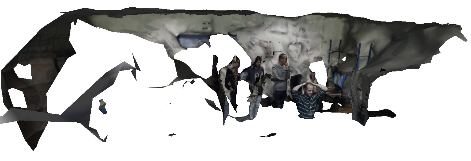
The resulting photos were then imported in Meshflow for reconstruction.
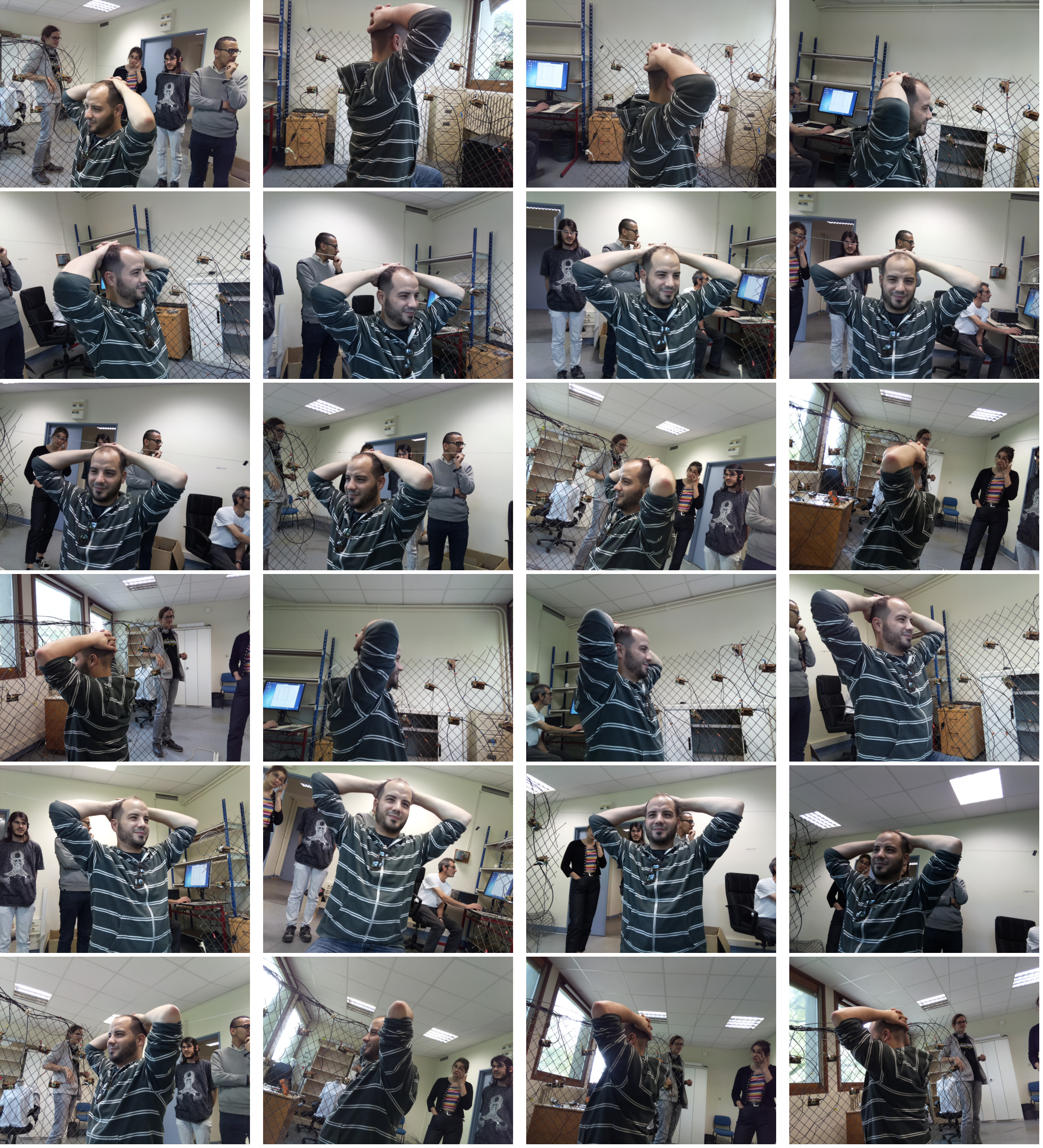

By the way this is Mejdi from Fabacademy 2018.
It works fine but the result is a bit disapointing because of the lack of details.
But it could probably be improved by adding uniform lighting and more cameras in a geodesic sphere fashion.
The complete process (triggering photos up to reconstruction) also needs to be fully automated under one single user click.
Design rules testing
As a group we worked on testing the 3D printer to define some design rules by printing several of these test files:- clearance
- angle
- overhang
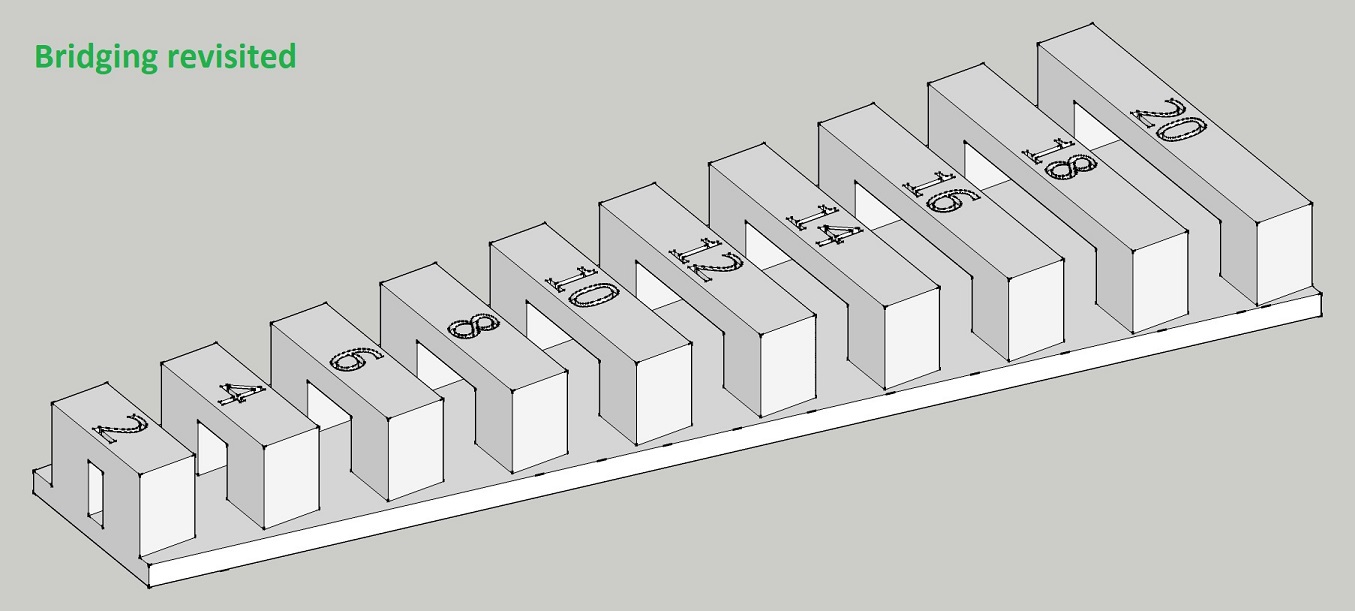
- bridging
- thickness
- dimensions
- surface finish
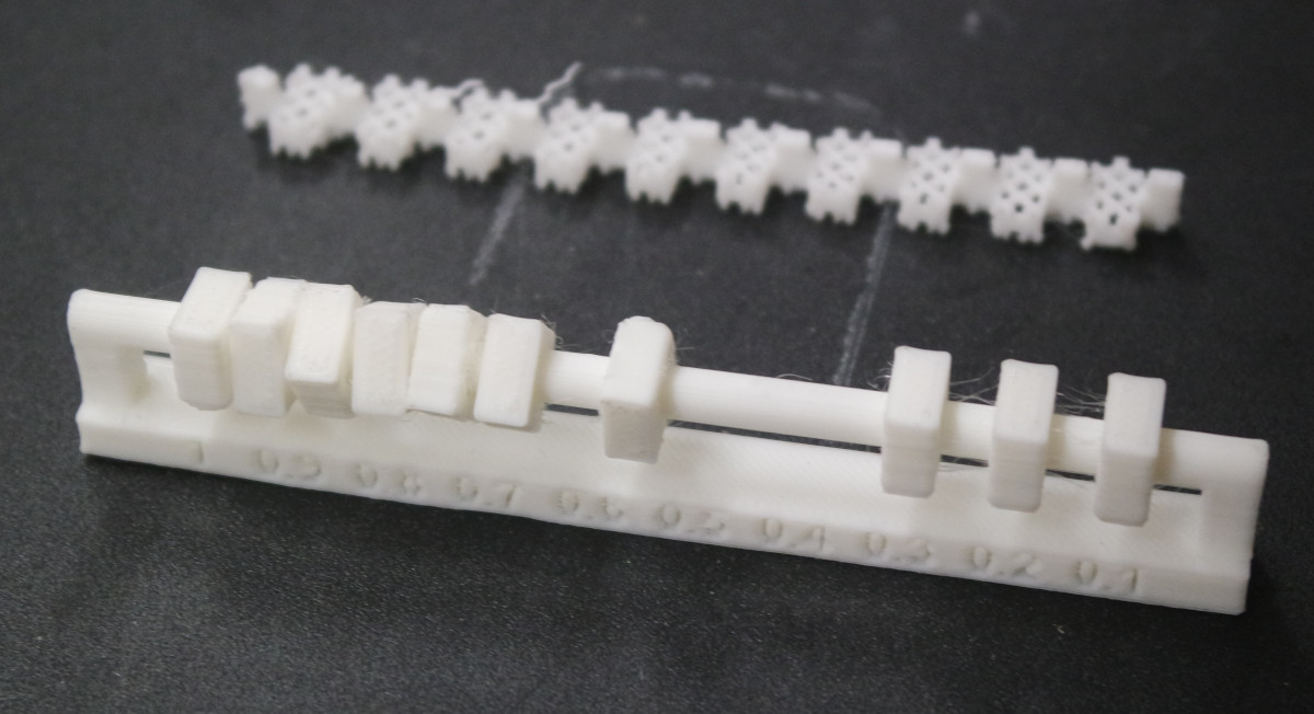
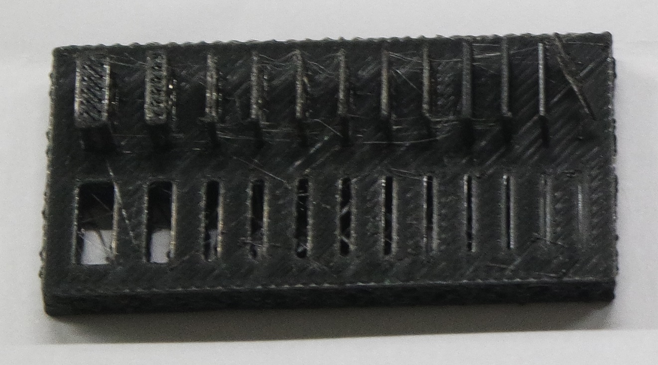
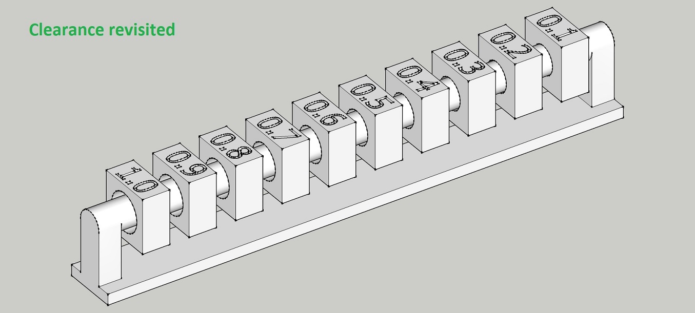
Clearance
The test shows that a 0.4mm clearance between parts need to be respected.Angle
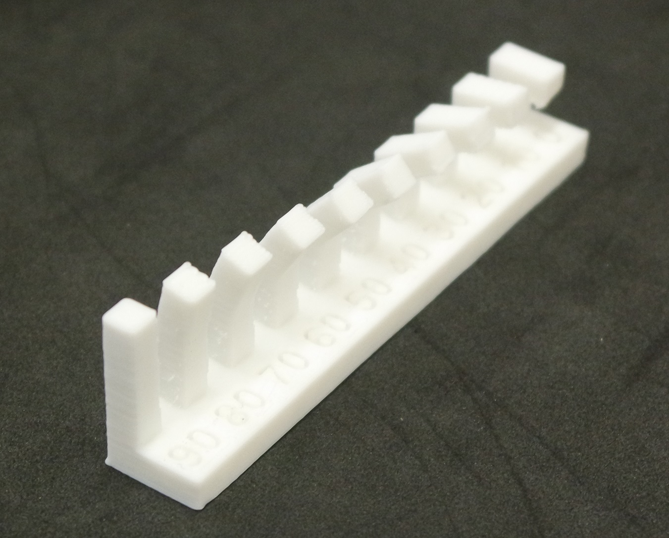
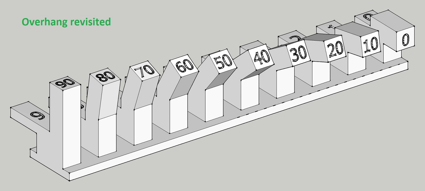
The printer can print angles up to 20° without problems.Overhang
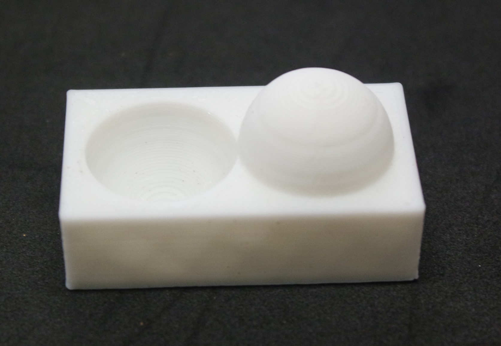
An overhang longer than 3mm must be supported for good results.Bridging
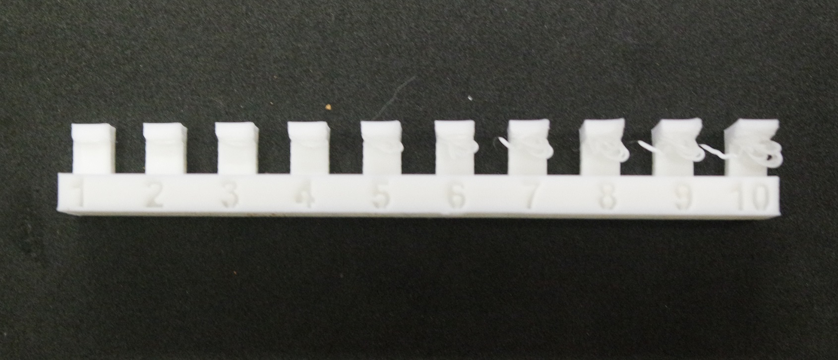
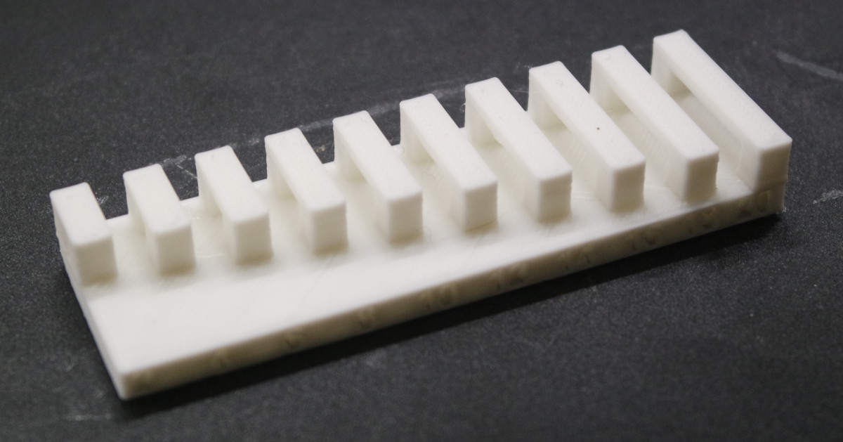
Bridging is perfect even at 20mm distance.Thickness
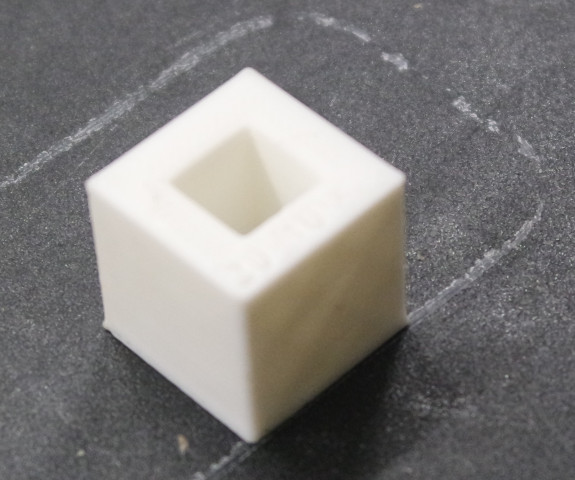
This test shows that a minimum of 0.2mm wall thickness must be respected. A 0.1mm wall could be printed but is unusable in practice.Dimensions
This test shows an internal dimension of 9.66mm and an external dimension of 20.14mm. That means the printer has to be calibrated.Surface finish
The surface finish looks good even with a 0.2mm layer thickness print.I also revisited a few of these test files so they can print faster and save on material.
Texts are engraved instead of being extruded out and are placed elsewhere, and the base of the meshes uses less material:
The new "Overhang" test file is a mix of the old "Angle" and "Overhang" files in one single test file.
You may download these new test files : Print_tests.zip
Printing a radial ball bearing
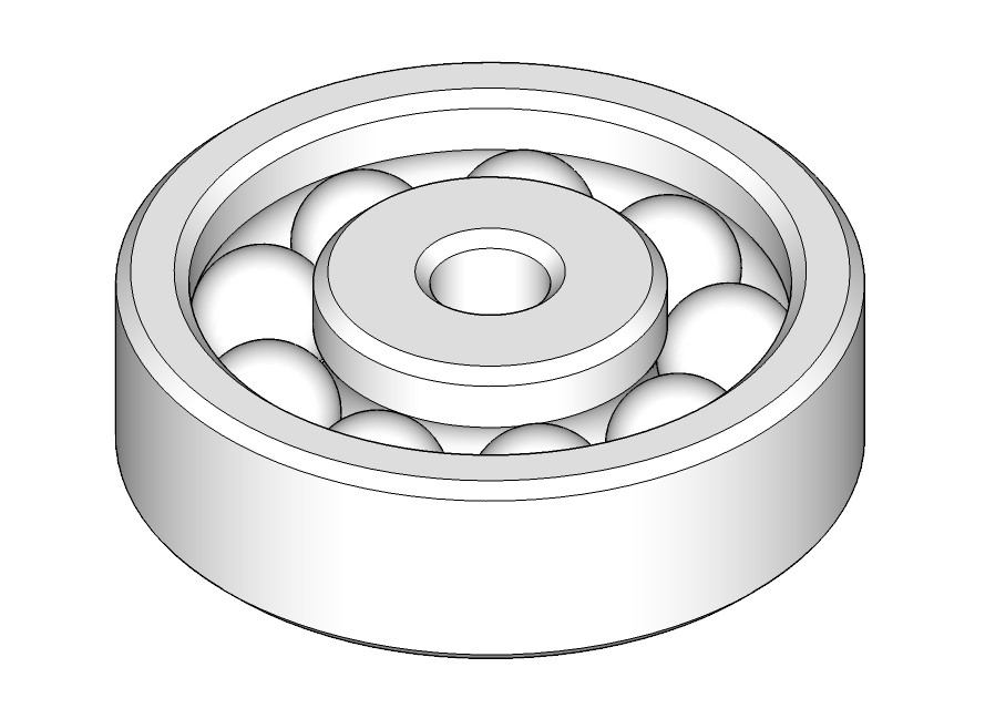
One of our assignement was to design and print an object that can't be made subtractively. I printed a radial ball bearing.Design step
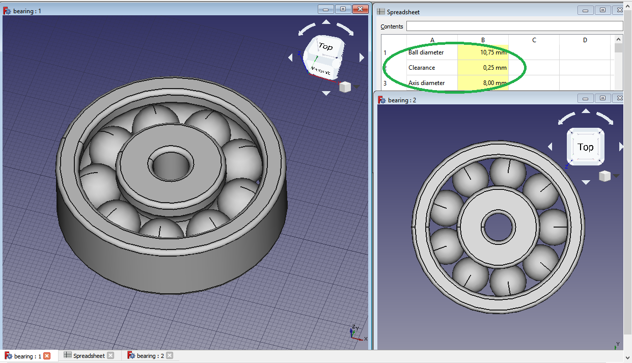
The bearing is made by extruding a section along a circle (revolution) and by adding an array of 9 spheres (balls) in the inside groove.I used FreeCAD and made it parametric with the use of a spreadsheet.
Here is the FreeCAD file.
The spheres are 10.75mm in diameter, the clearance is 0.25mm and the axis diameter is 8mm.
It was then exported as STL for 3D printing.
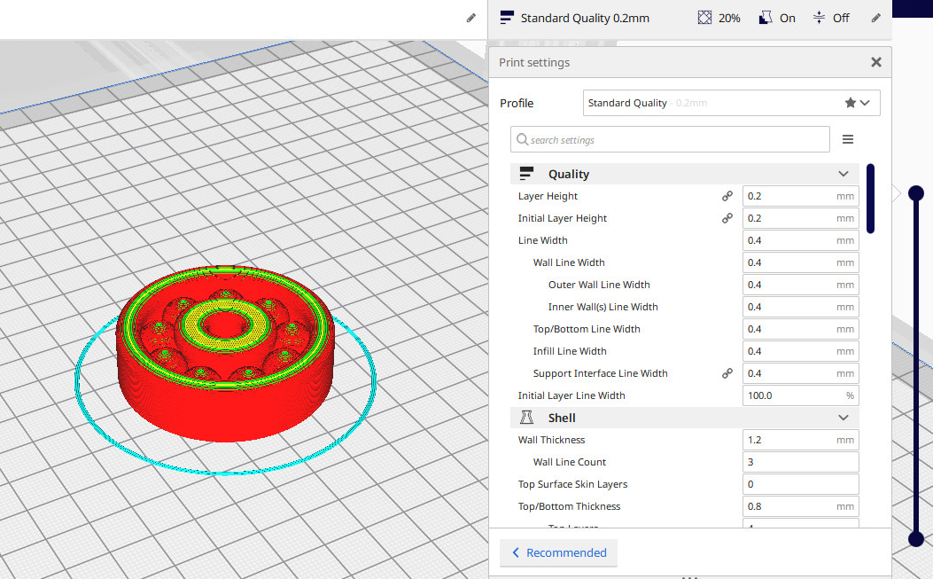
3D printing step
The STL was sliced in Cura with- 0.2 layer thickness
- adaptive mode
- 20% infill
- minimum support (65° / 20% density)
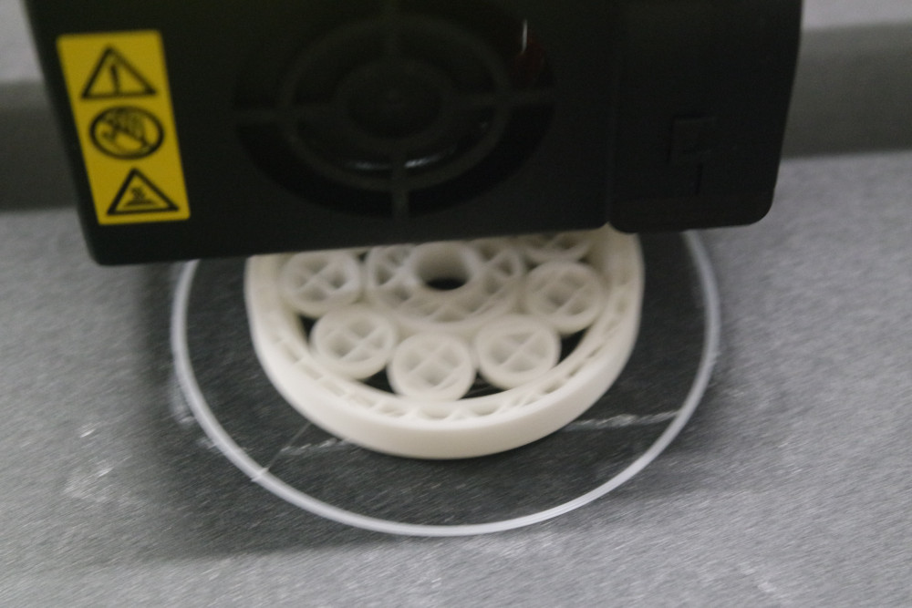
Printing time was 2h12 and it was printed on a Creality CR10-S Pro.
This is a photo taken at mid print (50%):
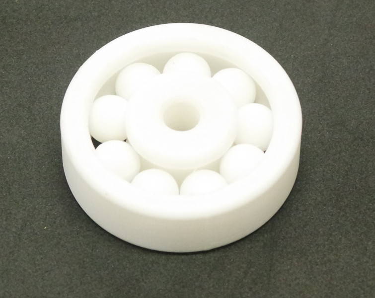
The supports were easily removed by hand and the bearing is rotating freely. Here is a photo of the final print:
3D scanning
In the past I worked for Konica-Minolta where I was in charge for testing, doing demos and selling their 3D scanners VI700, VI900, VI910 and VI9i.I also built a 3D scanner with a cheap webcam and a cheap laser emitting a green line. If I can find back photos and past work about it I'll add it here.
But that was something like 10 years ago or more...
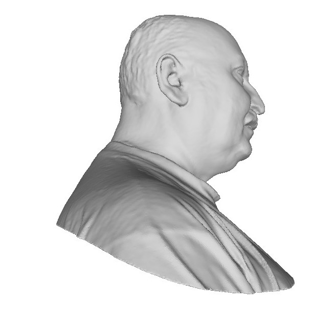
One of our colleague at work was retiring so I wanted to offer him a bust of himself.
The scan process was made on an old Konica Minolta VI-910 and the individual scans were registered and fused using David software.
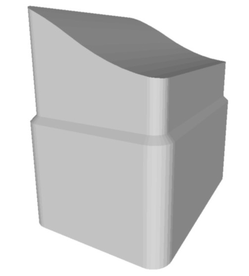
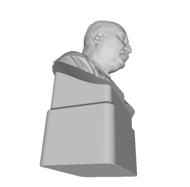
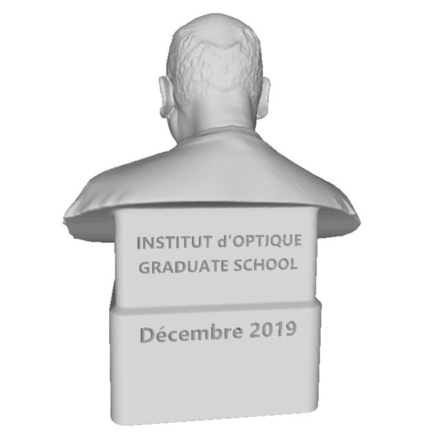
Then I modeled a block to be used as negative boolean and added a base with some engraved text on it then made it hollow with a 1.2mm wall thickness to later save on print time and material.
All these steps are performed in 3Dbuilder.
Slicing was done in Cura and printed on a Creality CR10-S Pro.
Finaly it was filled with plaster to make it heavier.
3D photogrammetry
In the past I tested several photogrammetry softwares and published a few articles on the subject with advices, result comparison, links, etc.I tried to cover the subject and to make it understandable for anyone.
The fablab of our school is situated in a very old building that needs some repair.
I took several photos of a broken part of the stairs at the entrance of the building and made a photogrammetry in Meshroom.
A ruler was included in the scene before shooting photos to be used as a reference for future scaling purpose.
The obtained mesh will be used later in the process as a subtractive boolean component.
It was then decimated in Meshlab, exported back, and imported in SketchUp to be scaled to real size (with the help of the ruler seen in the photos), and reoriented to match the XYZ coordinate system.
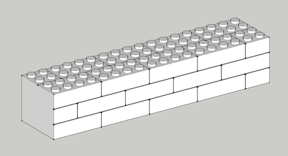
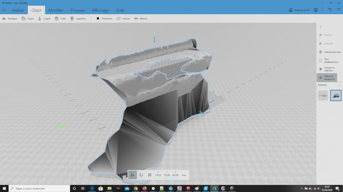
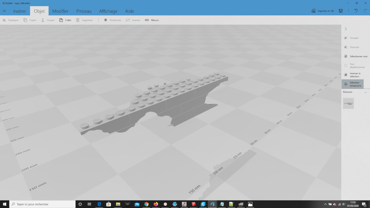
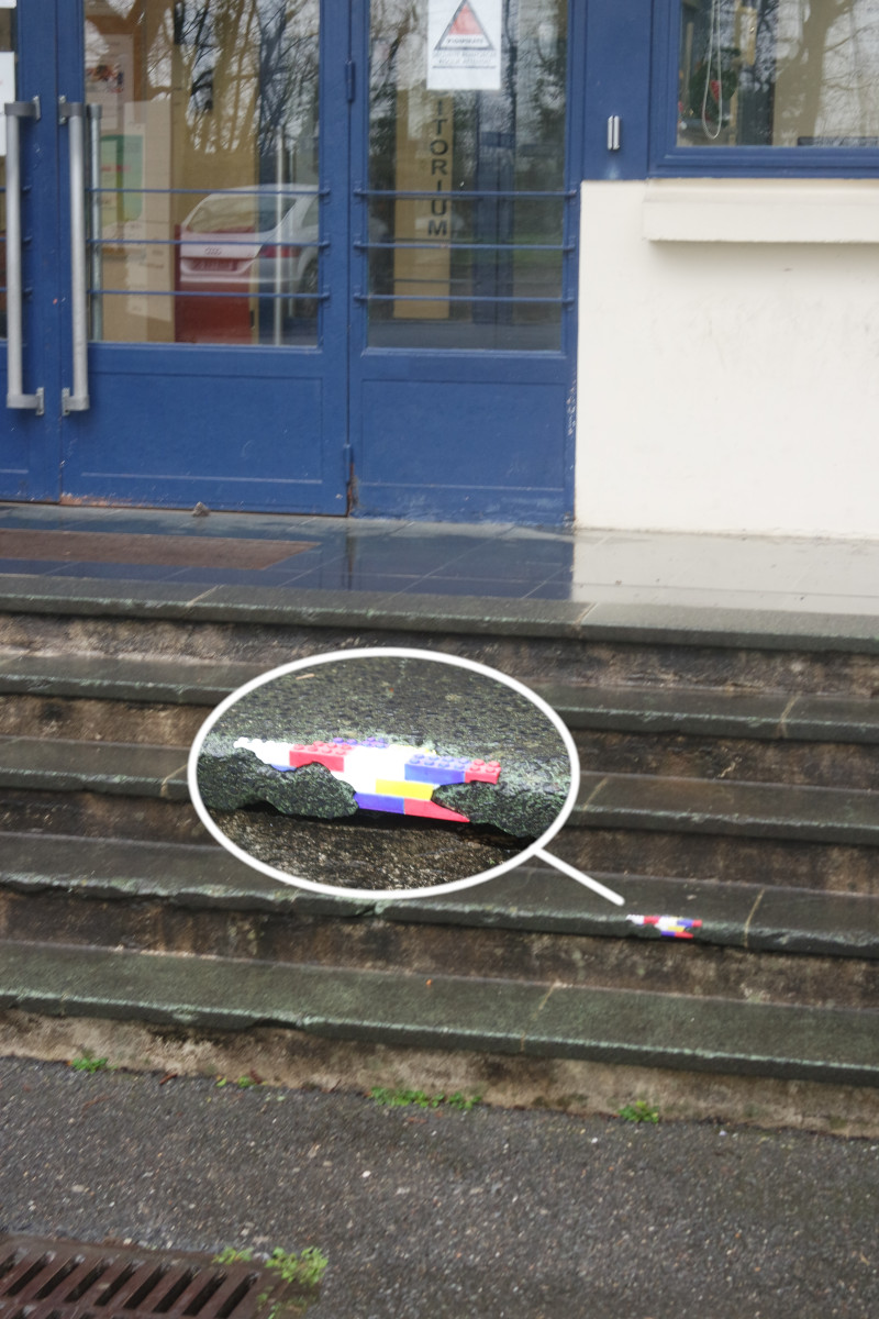
I wanted the repair to look colored and attractive by simulating Lego bricks being inside the concrete in a "trompe l'oeil" style.
So I designed a block simulating several assembled 4x2 Lego bricks, making sure to make it bigger than the damaged part.
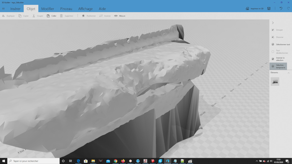
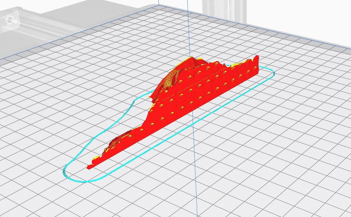
The mesh obtained in the previous step (photogrammetry) was used to cut the Lego bricks by a boolean operation in 3Dbuilder, and exported back as STL for 3D printing.
This is how it should look like if everything went well:
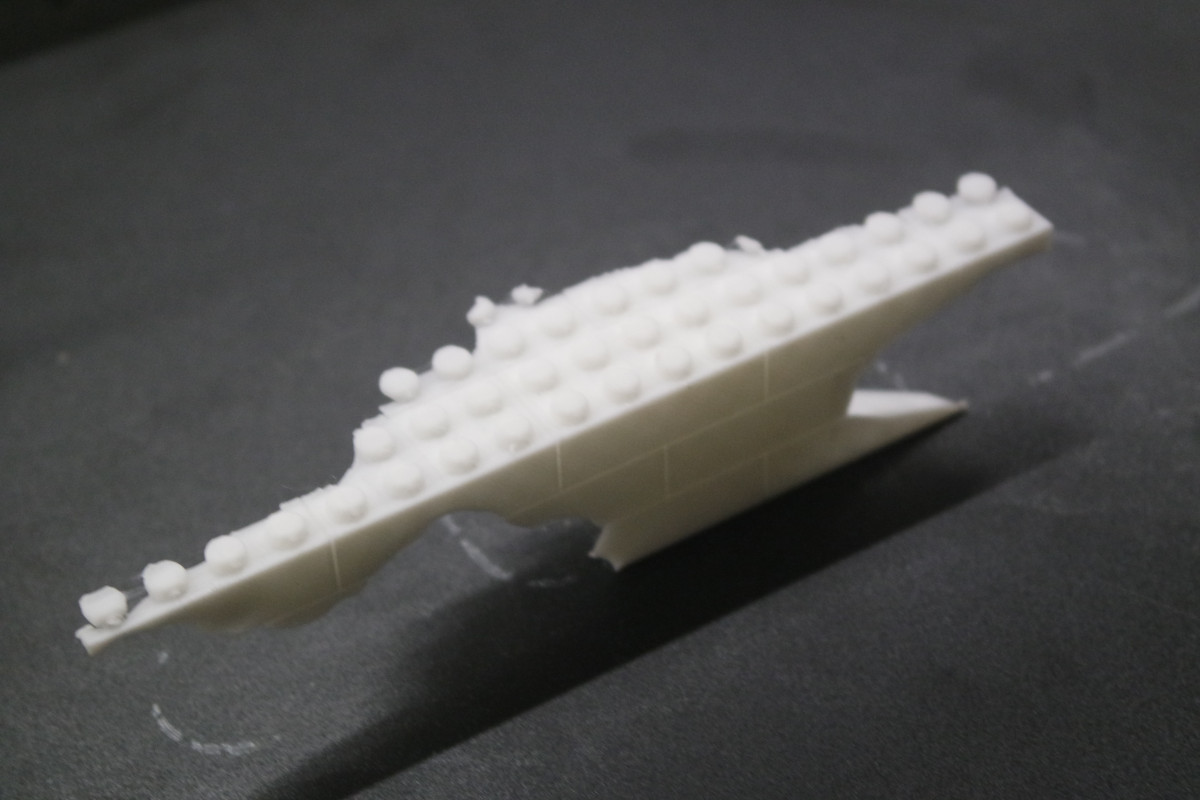
The printed part was painted with different colors to fake different Lego bricks, and then glued in place with prompt cement and fits perfectly:
Light stage (experimental)
Digitizing a leaving being is difficult because the subject might move between each shot (breathing, blinking eyes, etc.).The best way to avoid this is by using a photogrammetry stage where all the photos are shot at the same time. In order to do that I built a small photogrammetry stage consisting of 24 RaspberryPi equiped with Picam connected by network.
Only 24 RaspberryPi but already a lot of cables:
A home-made program (Python/PHP) synchronizes the RaspberryPi in order to trigger all the Picams at once.
The resulting photos were then imported in Meshflow for reconstruction.
By the way this is Mejdi from Fabacademy 2018.
It works fine but the result is a bit disapointing because of the lack of details.
But it could probably be improved by adding uniform lighting and more cameras in a geodesic sphere fashion.
The complete process (triggering photos up to reconstruction) also needs to be fully automated under one single user click.