5. Electronics production
For this week’s group assignment, we were asked to characterize our PCB milling machine. To this end, we first needed to get more familiar with the involved softwares, and test the physical limits of the milling process.
We used the provided drawings for the traces:

And the outline:

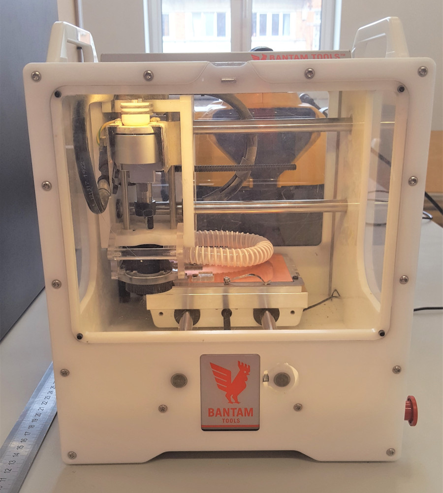
Bantam Tools Desktop PCB Milling Machine
Our FabLab is equipped with a desktop PCB Milling Machine from Bantam tools. It can consume 5x4 inch FR1 copper clad, and also supports double-sided circuit milling thanks to a clever use of registration markes on the build plate.
The machine is handy, and takes minimal space on a desk:
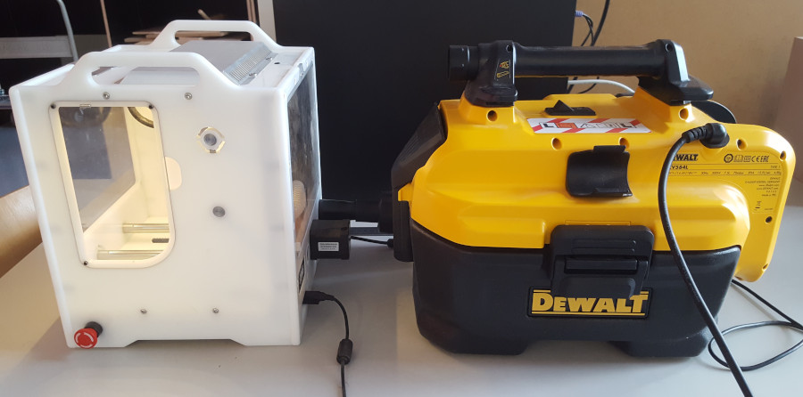
In our case, the most noisy and bulky equipment involved in PCB milling is actually the exhaust fan, connected directly to the milling machine through a pipe:
Material
We start with a standard 5x4 inch single-sided copper clad.
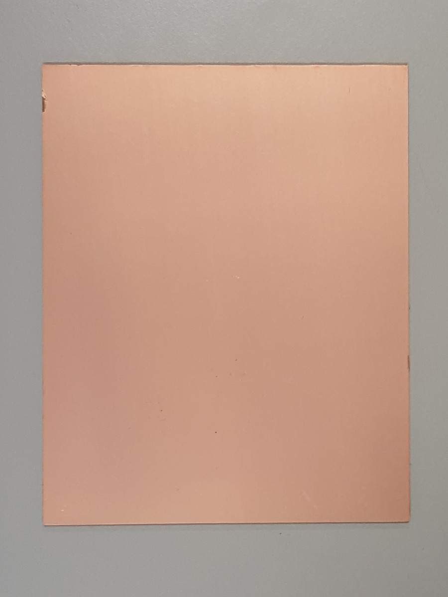
We then tape it to the build plate with double-sided tape.
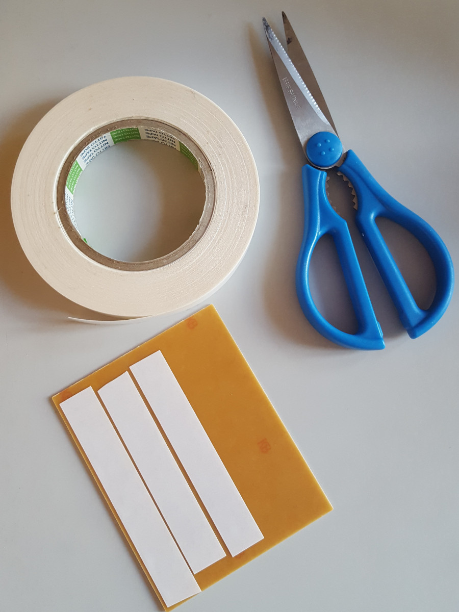
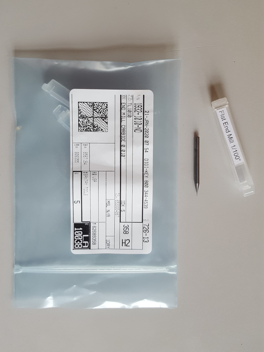
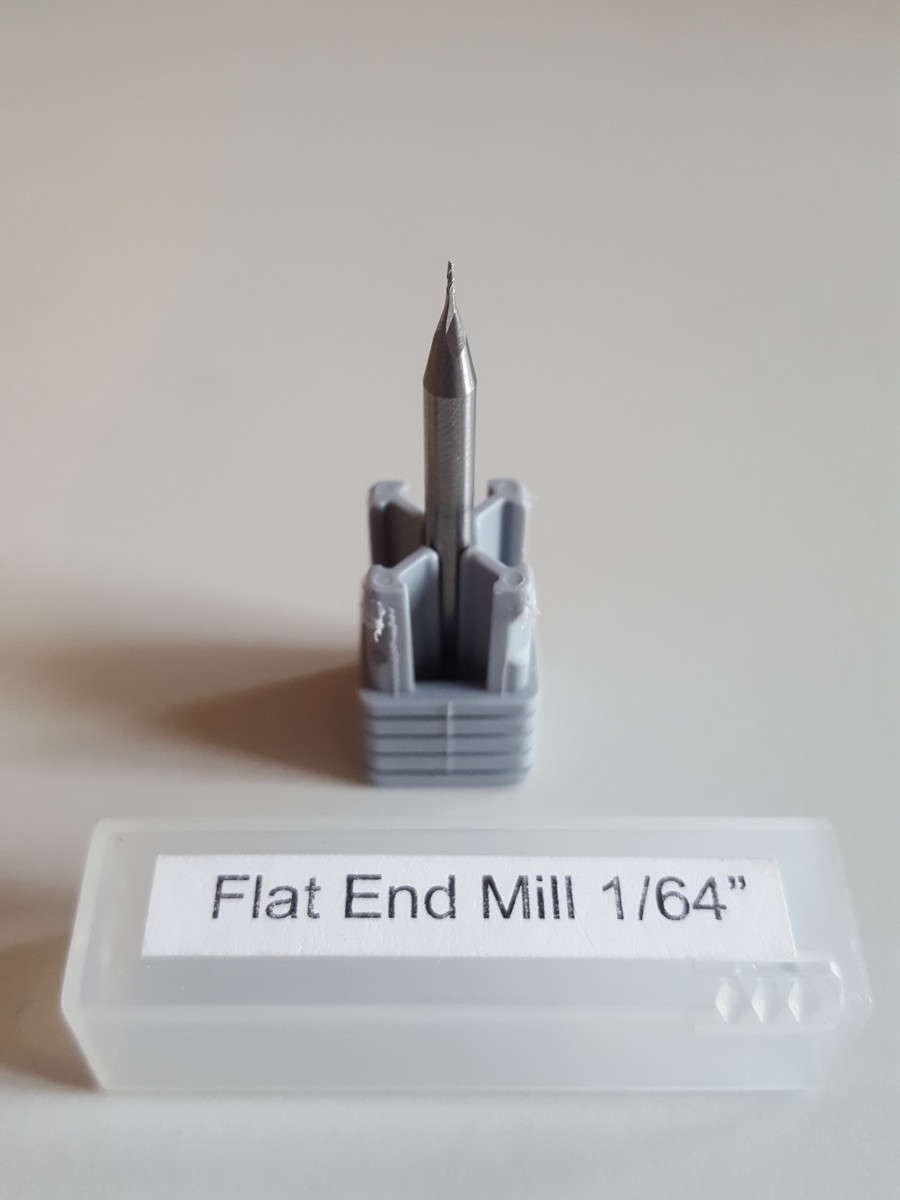
For the assignment, we will be testing a 1/100” and a 1/64” tool, both made from carbide. We also use a 1 mm flat end mill for carving the outline.
Work flow
The first step was to estimate the turn on the machine, and execute homing. When inserting the milling tool, its height also needs to be calibrated. Thanks to the electrical conductivity of the tool, this is easily achieved by touching the build plate, which closes the electrical circuit and triggers the machine’s limit sensor.
Using the same procedure, we could estimate the width of our copper clad to be 1.74mm.
Once this value is known, we head over to mods, using the G-code -> mill 2D png program. After loading the correct png file, we set the following settings in the mill raster cell:
- tool diameter: 0.0156 in or 0.01 in
- cut depth: 0.07 mm
- max depth: 0.14 mm
- offset number: 10
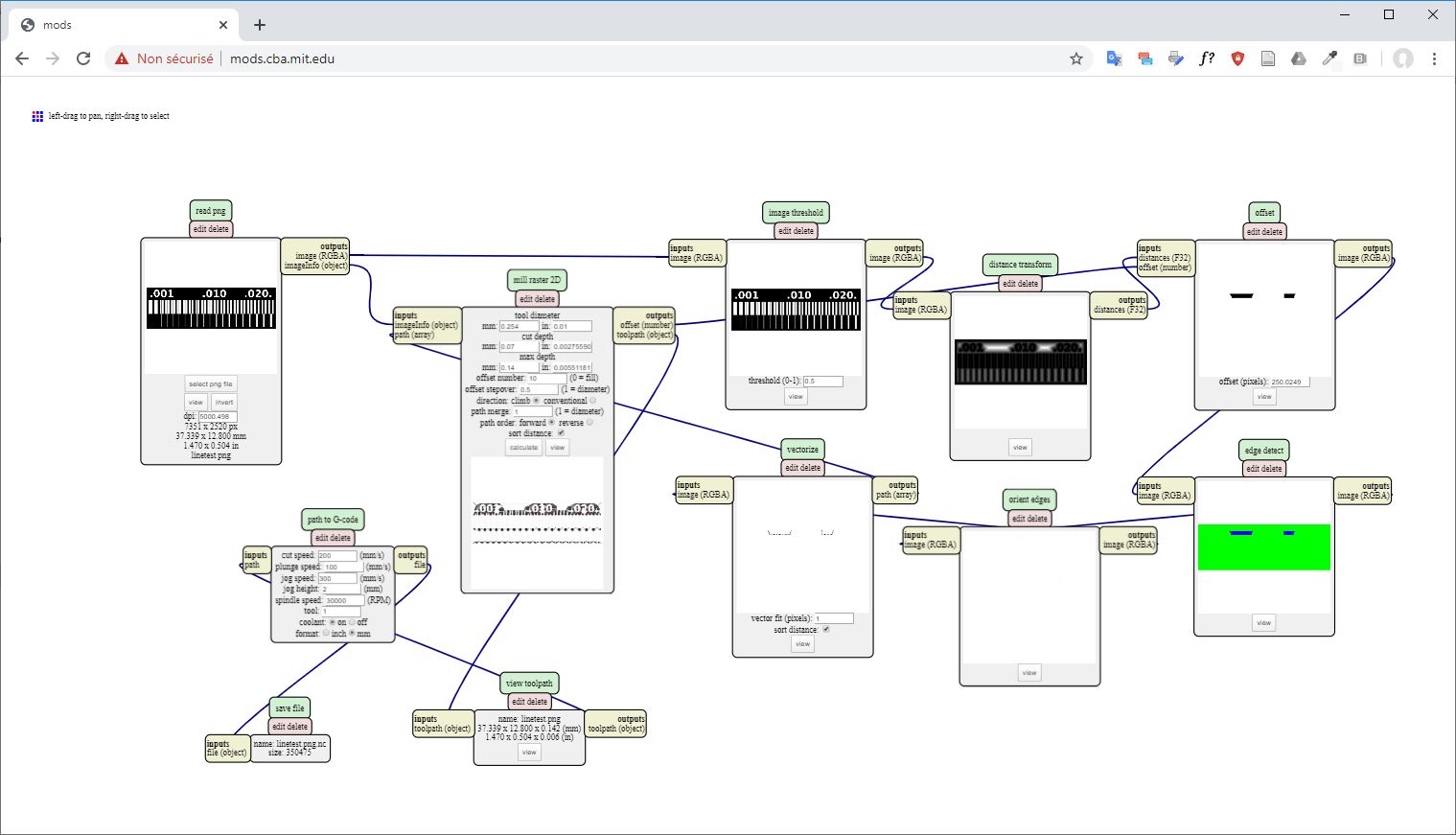
Finally, in the path to G-code cell, we use the following:
- cut speed: 200 mm/min
- plunge speed: 200 mm/min
- jog speed: 300 mm/min
- jog height: 2 mm
- spindle speed: 30.000 RPM
- format: mm
The milling process took about 30 minutes. For cutting the outline, the same settings were used, except the following in mill raster:
- tool diameter: 1 mm
- cut depth: 1.74 mm
- max depth: 1.74 mm
- offset number: 1
This means that the outline is performed as a single cut, which is feasible thanks to the strength of our 1 mm milling tool.
After this, the G-code is exported from mods, and imported in the Bantam tools software. The only critical step is to remove the G54 instruction from the beginning of the G-code, as this instruction is not implemented in our G-code flavour.
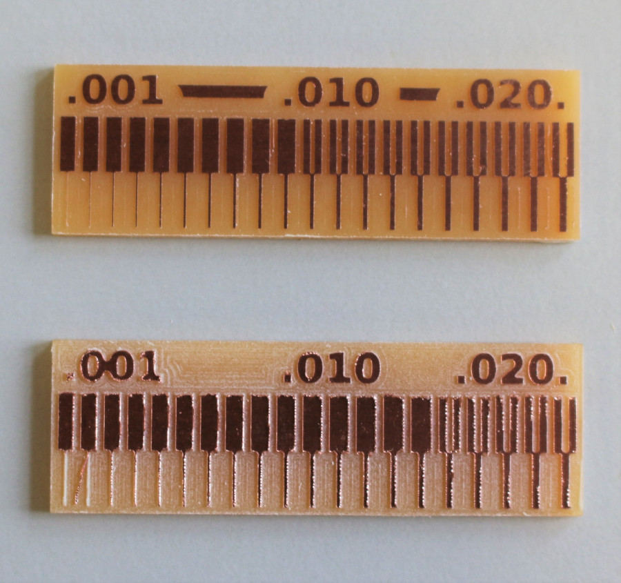
The end result of the 1/100” (top) and 1/64” (bottom) shows the practical accuracy of our machining. It should be noted that the 1/100” tool is brand new, which might explain some of the difference in the results. In that case, even the finest lines were successfully isolated.