Week 8 - computer-controlled machining
This week was about computer-controlled machining. The main objective of this week was to be able to choose the right speeds and feeds for the machine depending on the cut materials mostly to enhance the safety and avoid to break the cutting tool while cutting (this situation possibly leading to damages).
FAB ACADEMY 2020 source
20200311 Computer Machining from Academany on Vimeo.
My Assignment
The group assignment was about characterizing the CNC machine of the ULB FABLAB.
This week assignment was about building something big with the CNC (computer numerical control) machine. I decided to make an enclosure for the PRUSA 3D printer. I followed some advices from the printer manufacturer to design the enclosure. I made the CADs files with SolidWorks.
Enclosure concept on SolidWorks
I designed the parts one by one in SolidWorks where I set a bunch of equations and variables such as the height, width and length of the box, the width of the boards and the tolerances. Then I created an assembly file.
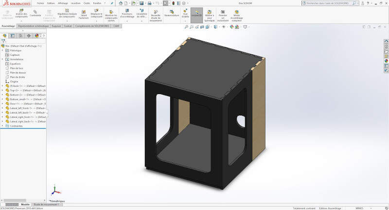
Assembly of the parts in SolidWorks
In the following video there is an animation of the assembly made with SolidWorks.
Assembly of the PRUSA enclosure
Manufacturing on SolidWorks
For this part I mostly followed this tuotrial and the 2019 FABACADEMY WEEK08 - assignment written by Gilles Decroly, one of our instructors. As he suggested I installed and used HMSWorks a SolidWorks plug-in developed by Autodesk that added a new CAM tab in SolidWorks.
In this section I will explain how I made the CAM-toolpath on the most complex part : the front lateral left side.
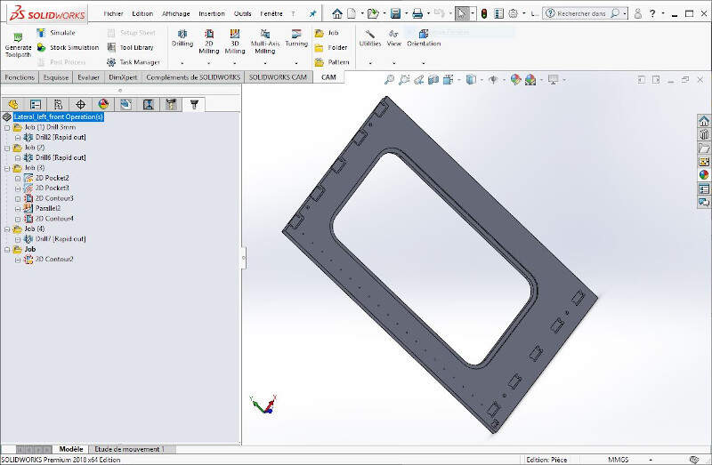
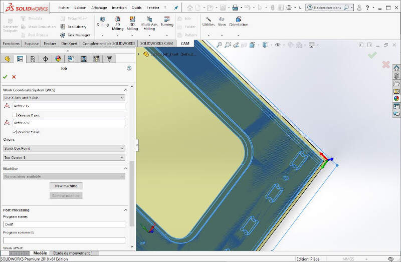
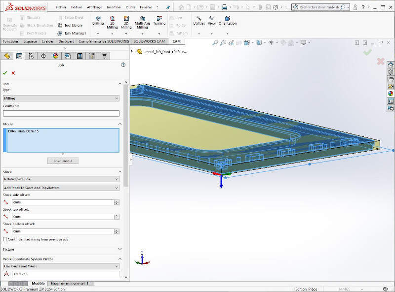
I first created a Job.
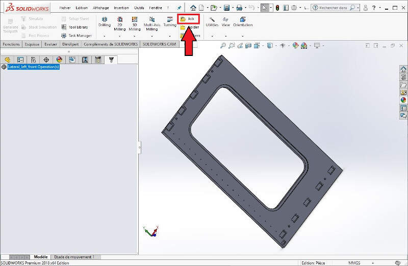
In the Job settings you can define the shape of the stock.
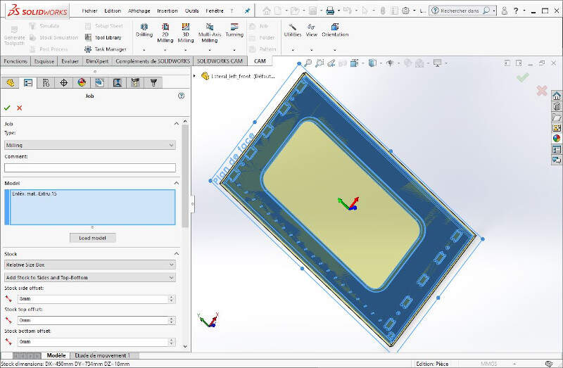
You can also set the origin of the tool frame. I personally chose a corner of the part. It makes it easier to assess the alignment of the frame with the stock in the machine.
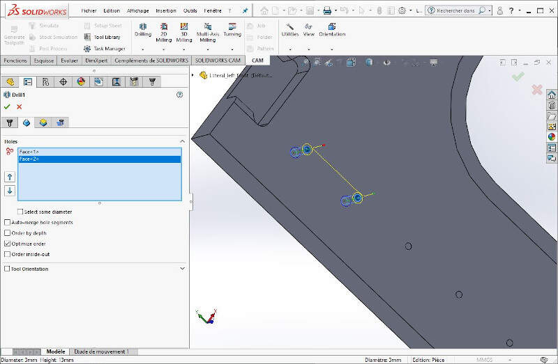
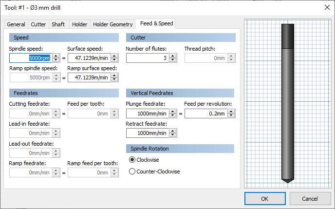
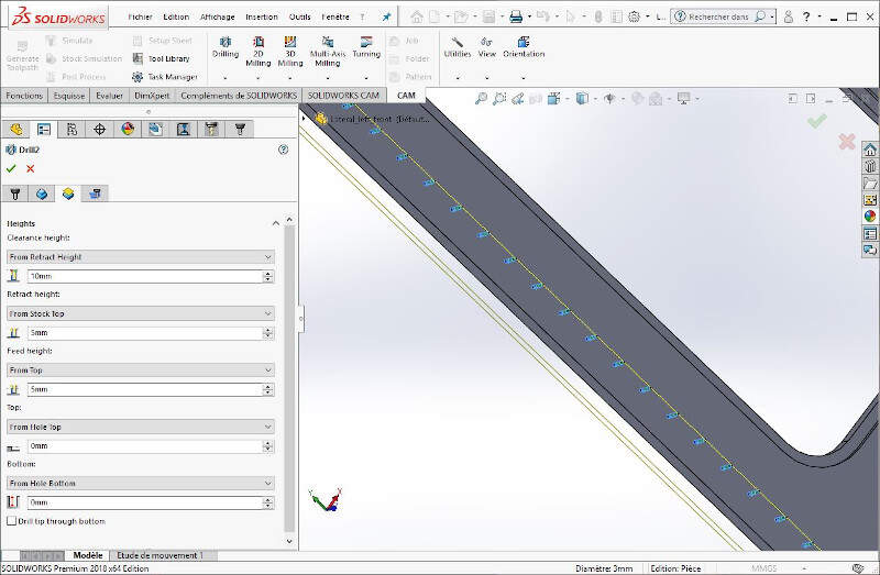
The first operation I set for this job is drilling the holes for the door hinges. To do that I chose a 3mm drill.
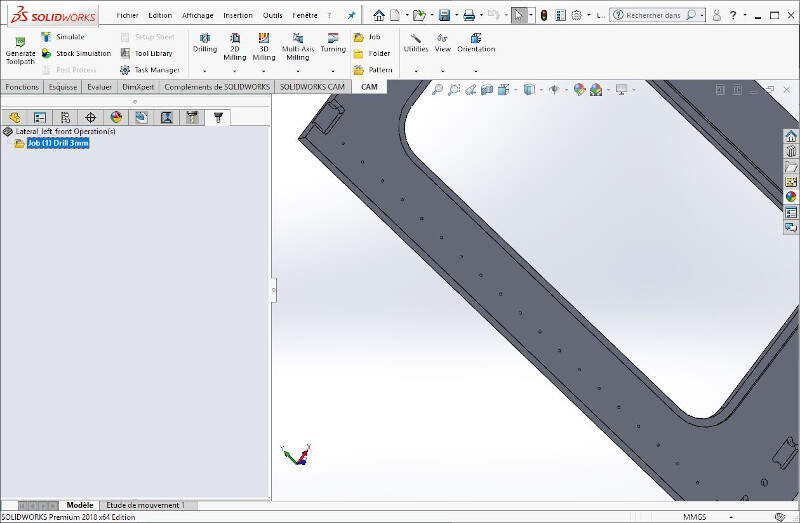
I selected all the holes one by one.
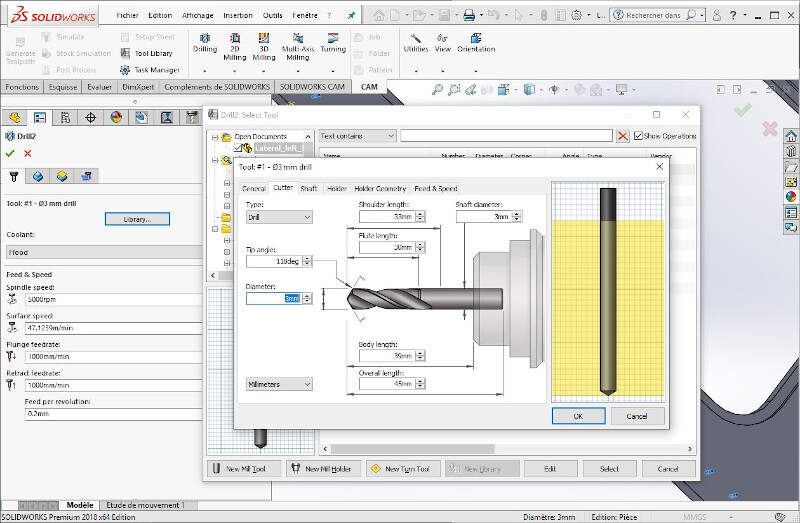
I set the tool.
I defined the right speed and feed rates.
I made sure that the tool was retracted enough between each drillings when passing from one hole to the other.
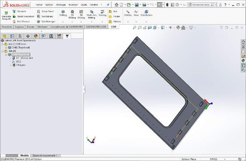
Afterwards I created a second Job in which I use a 6mm flat end mill to drill four centering pin holes.
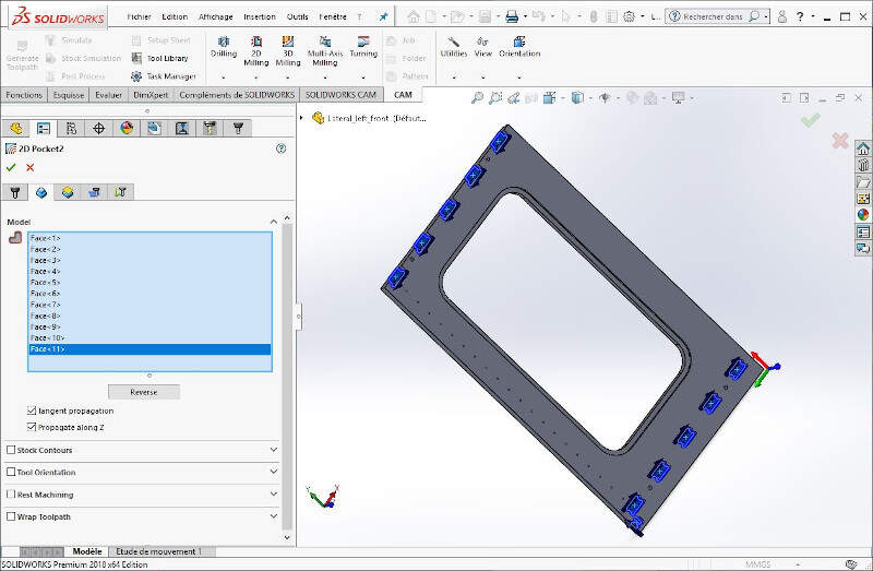
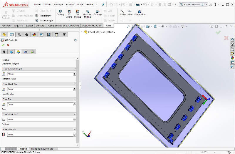
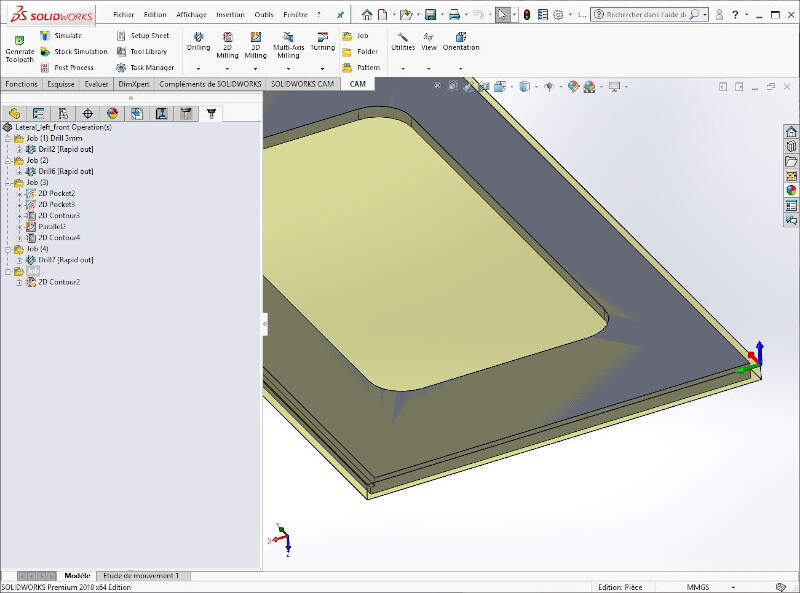
Then I created 2D pockets with the same tool by selecting the adequate faces as the following picture shows.
I checked the tool retraction parameters.
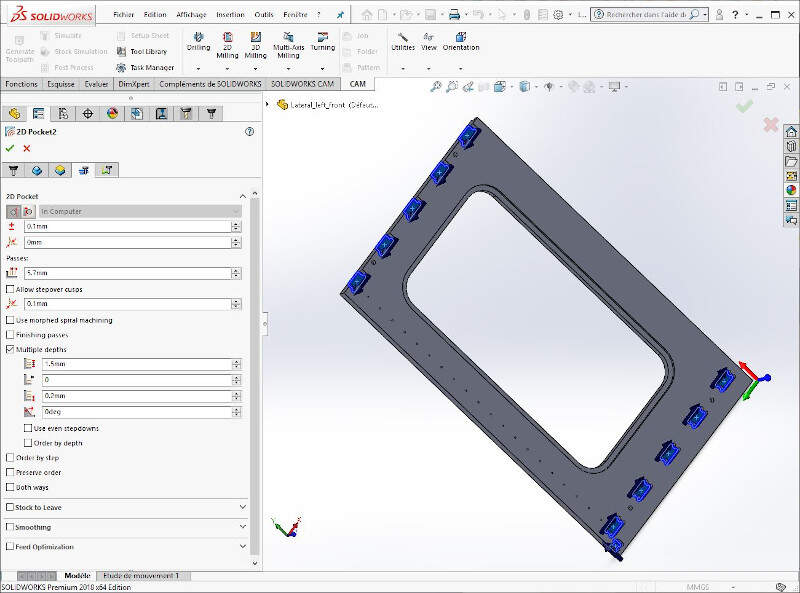
I ticked the box Multiple depths and set a reasonable cutting depth (commonly the half of the tool diameter).
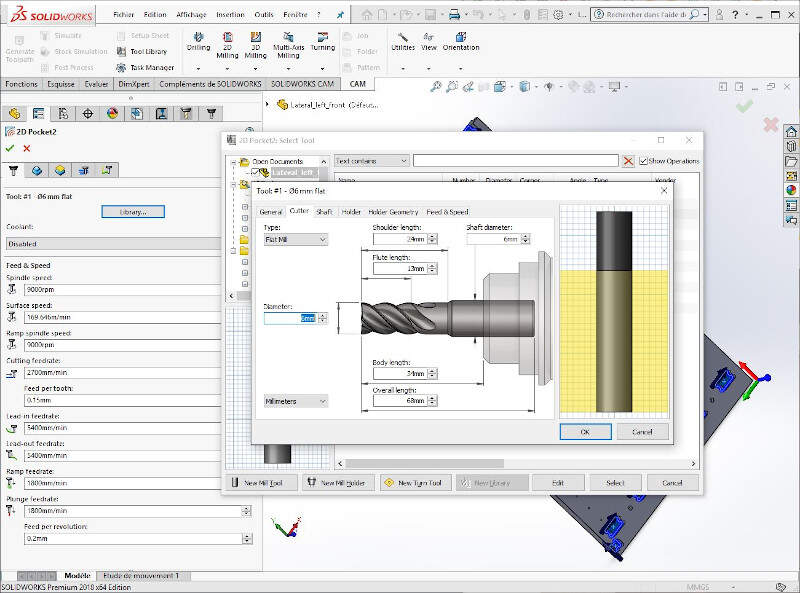
I set the dimensional characteristics of the tool.
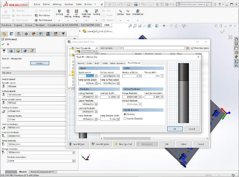
I defined the speeds and feed rates of the flat end mill.
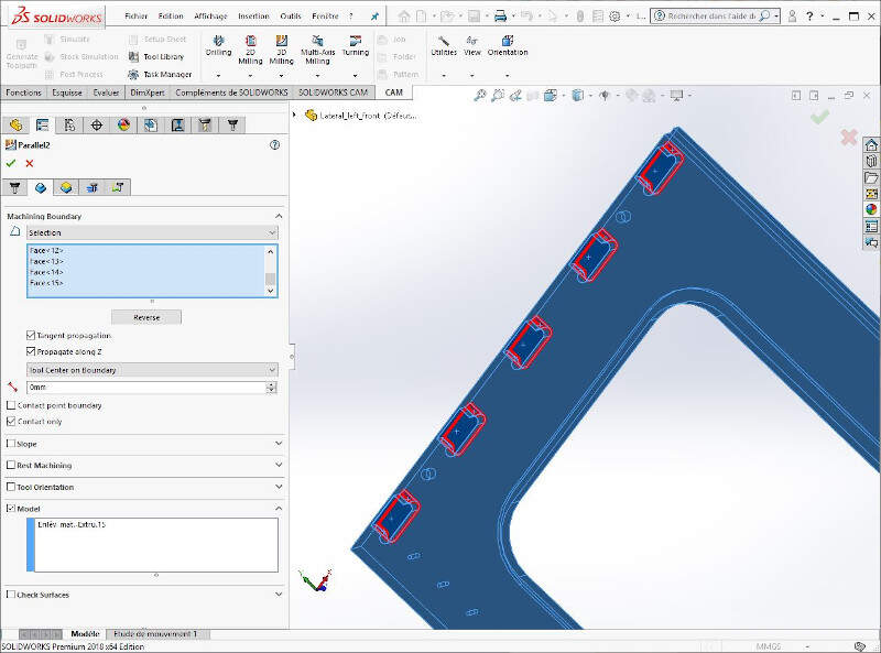
Then I set a Parallel 3D operation to 3D mill the pockets shown on the following picture.
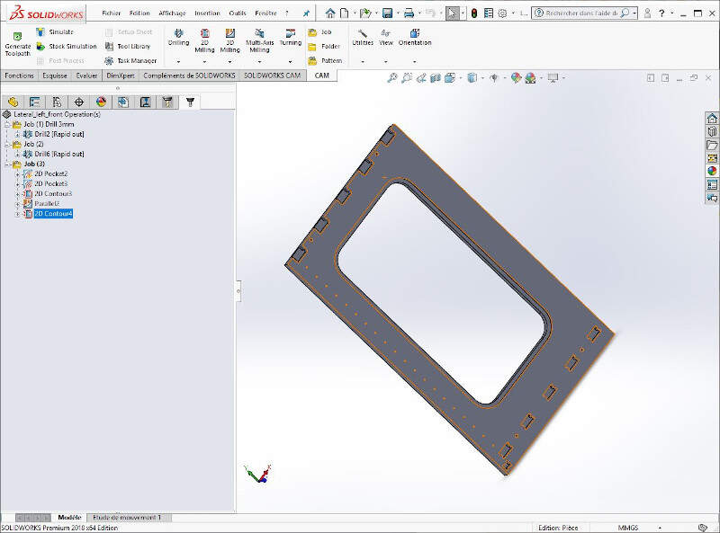
After setting a few more toolpaths, I finished by cutting the part edges with the 2D contour.
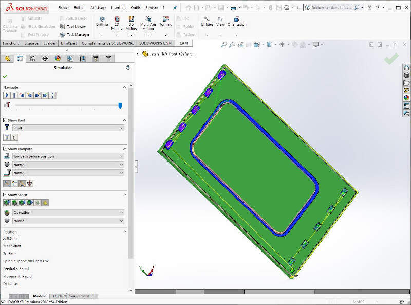
At the end I made a last check with the Simulation tool of SolidWorks.
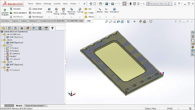
Since the part must be machined on both sides I created a fifth Job where I set the stock upside down as one can see on the following picture.
I defined a 2D contour to cut the clearance on the part side.
Before generating the nc-files I clicked a last time on Generate Toolpaths to refresh and renew the toolpaths calculation.
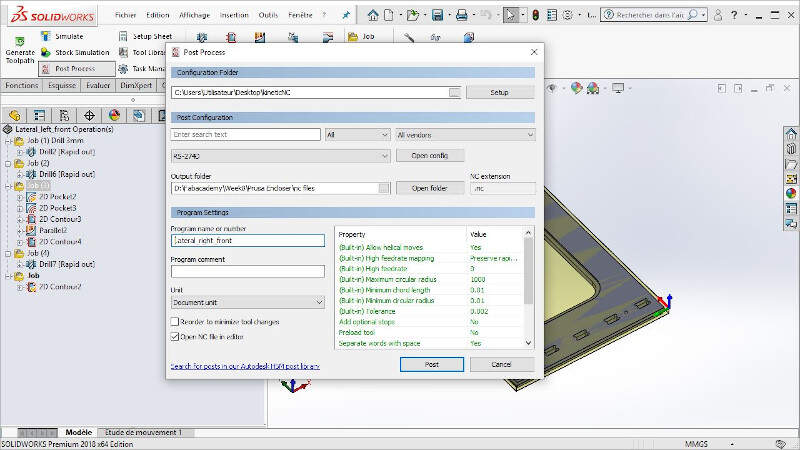
At the last I clicked on Post Process and generated the nc-files that we be used by the CNC machine. In the kineticNC folder there is a .cps file (kinetic-nc.cps). It is the setting file of the CNC HIGH-Z S-1000/T CNC ROUTER and it needs to be known from the Post Process operation in such a way that it will generate a code that will be properly interpreted by the right machine.
Equipment
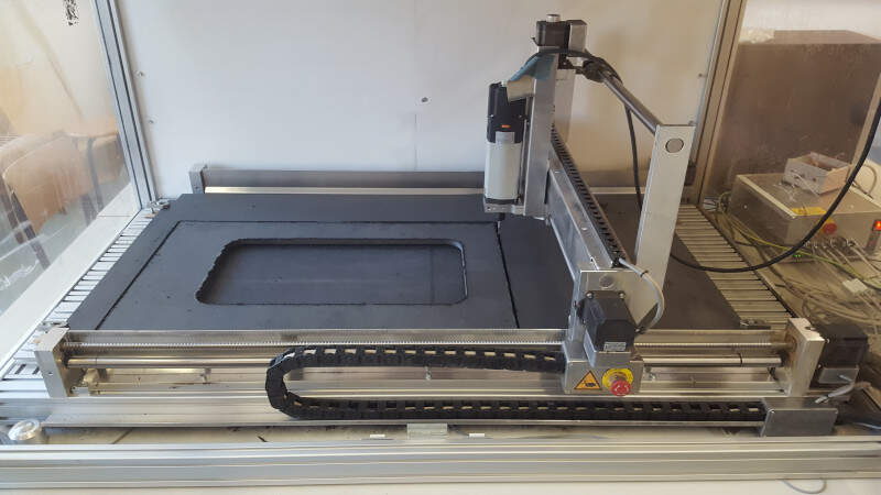
The CNC machine of the ULB FABLAB is the HIGH-Z S-1000/T CNC ROUTER.
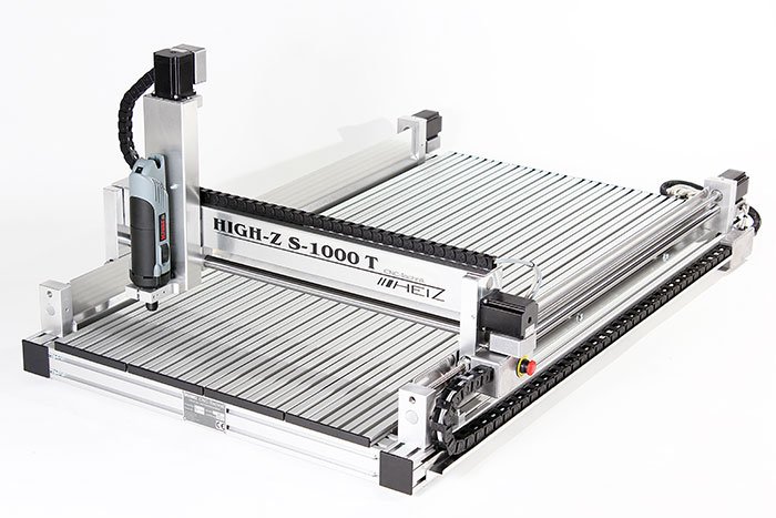
HIGH-Z S-1000/T CNC ROUTER
I also used a 3mm drill, a 8mm drill and a 6mm End-Flat Mill.
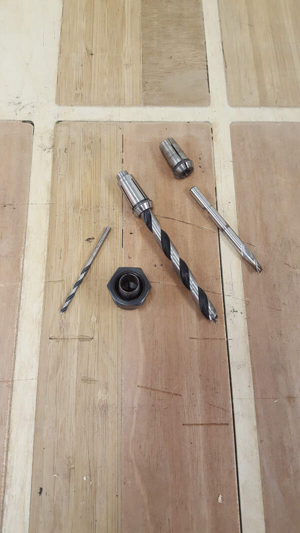
Tools on the CNC machine
Software - CNC machining on KinetiC-NC
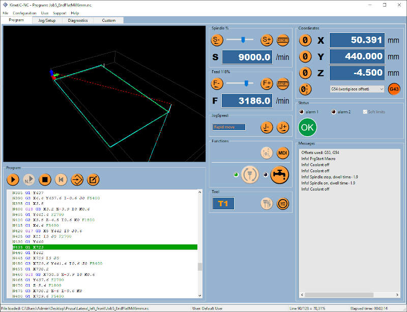
The user interface of the HIGH-Z S-1000/T CNC ROUTER is KinetiC-NC. It was already installed on the computer linked to the CNC.
In the "Program" tab you can load a new file (a .nc file or a .GCODE file) and see how the part fits in the CNC machine.
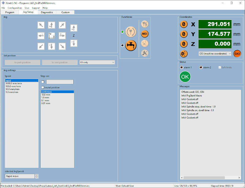
In the "Jog/Setup" tab you can start the homing of the CNC machine, you can change the position of the cutter in the X-, Y- and Z- directions, you can also customize a reference frame.
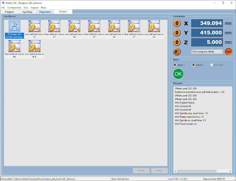
On the "Custom" TAB there is a function the set the position of the Z-axis to zero.
First I placed a 8mm drill on the CNC machine. I set the Z-axis on zero when it was touching the sacrificial layer. I also set the X- and Y-axis by making sure that all the files prepared later for this part would fit in the cutting area. Then I drilled the centering pins pattern on the sacrificial layer with the 8mm drill.
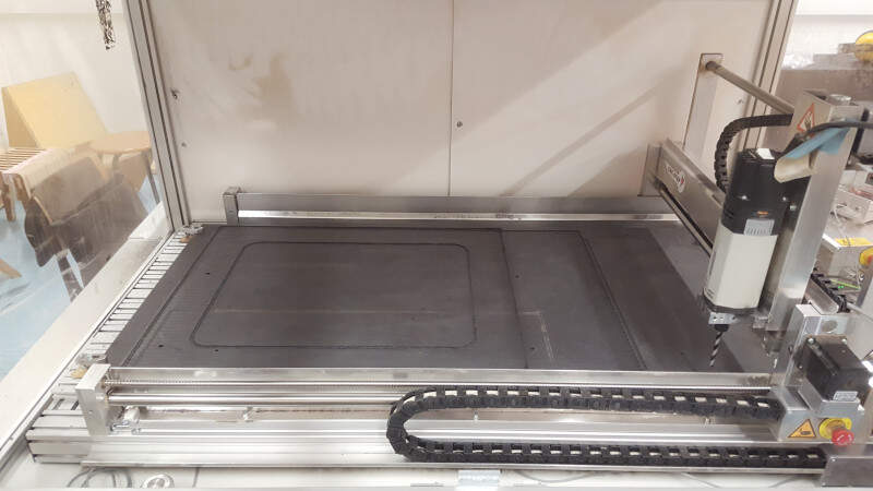
Drilling the centering pins pattern on the sacrificial layer.
Afterwards I placed the stock on the sacrificial layer, I set the Z-axis on zero when it was touching the stock and I drilled the same centering pins pattern on it with the same drill and without changing the X- and Y-axis.
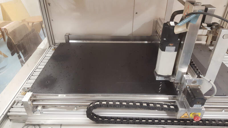
Drilling the centering pins pattern on the stock
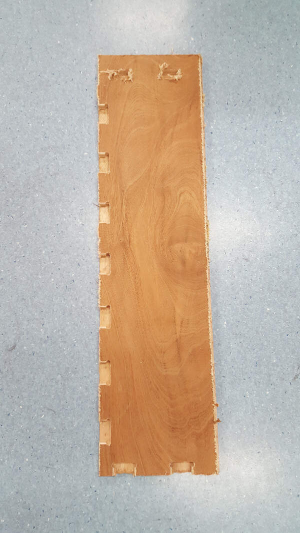
Then I placed a 3mm drill for the small holes and a 6mm End-Flat Mill for the rest of the operations and I repeat the same operations with the two other files. When all the operations were done on that part face I cleaned the bed of the machine and I cleaned the edges of the part. I placed wooden dowels on it and I turned part on the other side.
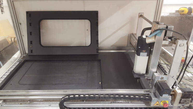
Placement of the part on its other side
At that point the part was correctly settled to be cut on the other side.
Second face ready to be cut
Assembly
Once all the parts were cut I had to assemble them. First I smoothed the edges of the parts with some sandpaper.
Cleaning of the parts with sandpaper
I used some glue to paste them.
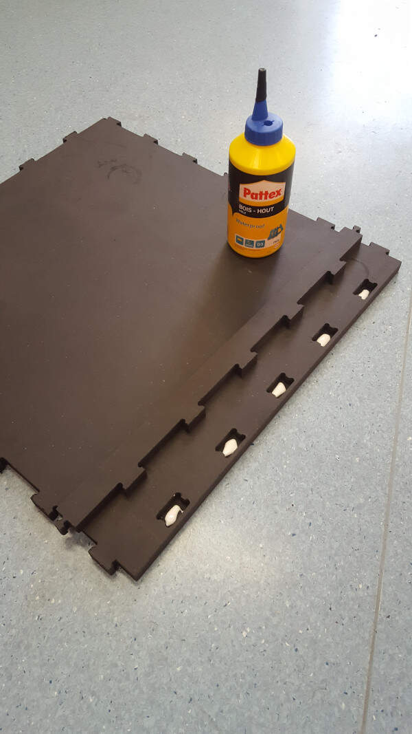
Assembly with some wood glue
And here is the result.
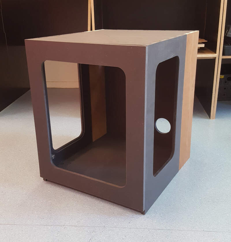
PRUSA enclosure with closed door
When the door is open.
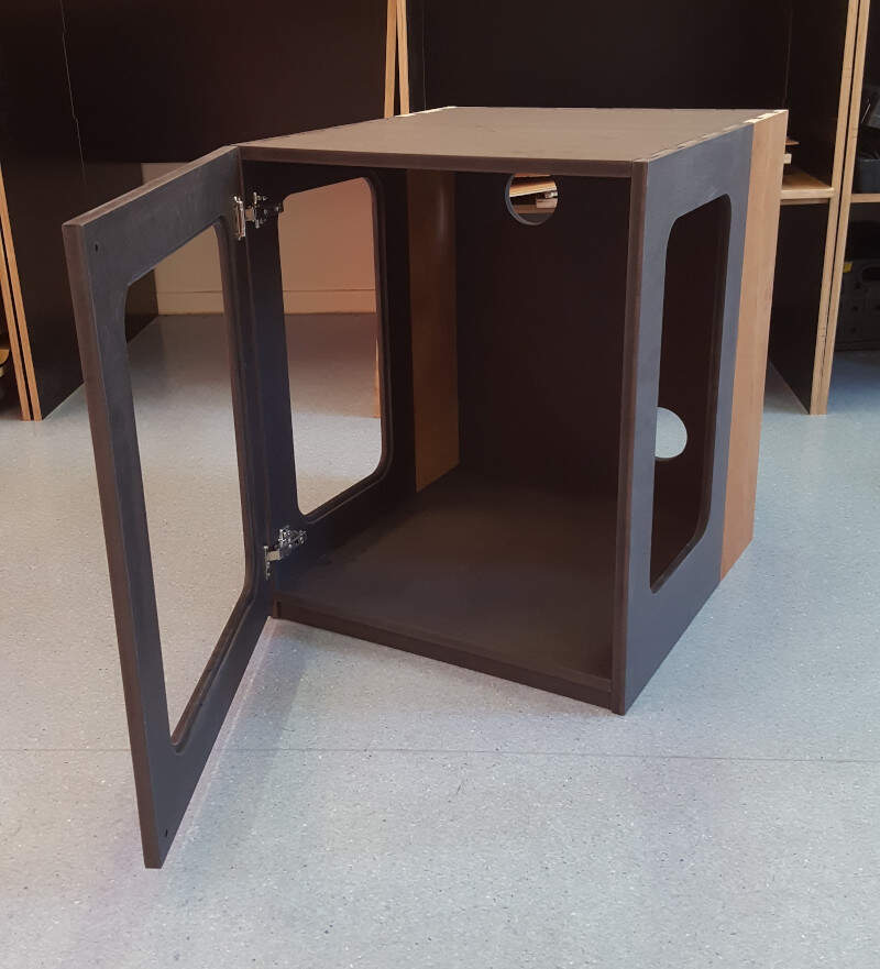
PRUSA enclosure with opened door
You'll notice that the joints are invisible be it for the hidden notches or for the side to side notches.
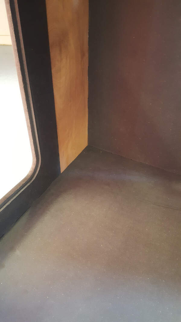
Detail of the inside - the joints are invisible

Detail of the back side
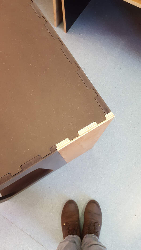
Detail of the corner
But for some reason (probably because the machine is not precise enough on the Z-axis) some notches were not properly 3D shaped. As a consequence they leave a space in the joint that makes it less esthetic.
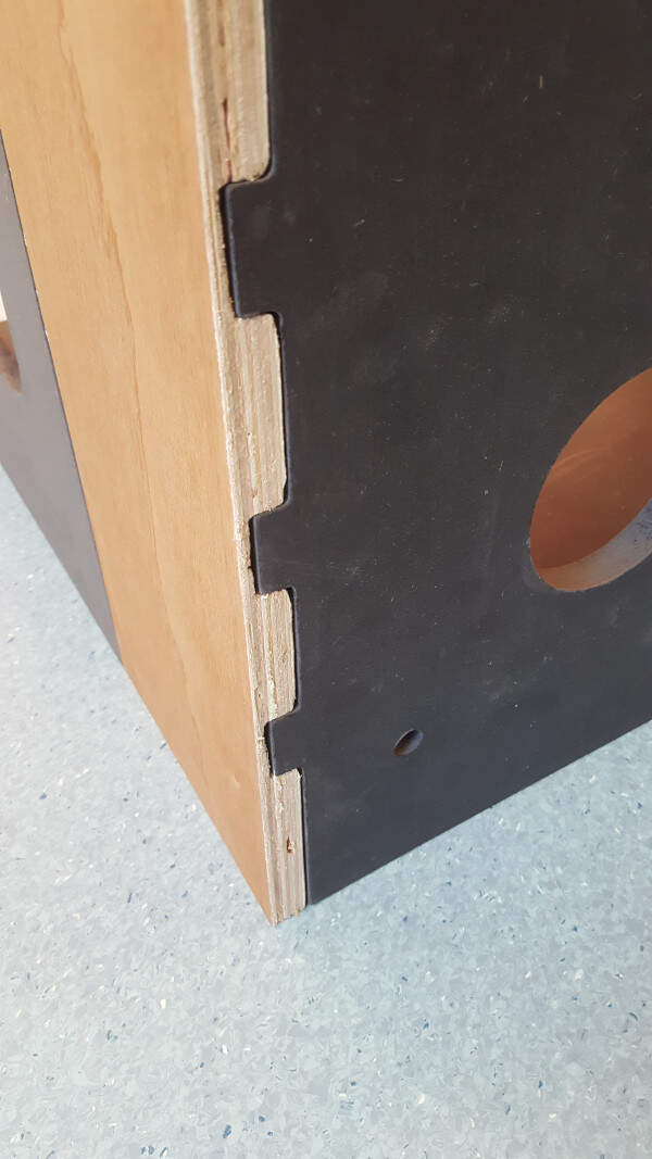
Defect on the back side
This can be also seen on the following picture. To not waste the board this issue can easily be solved by adding some wood paste in the holes.
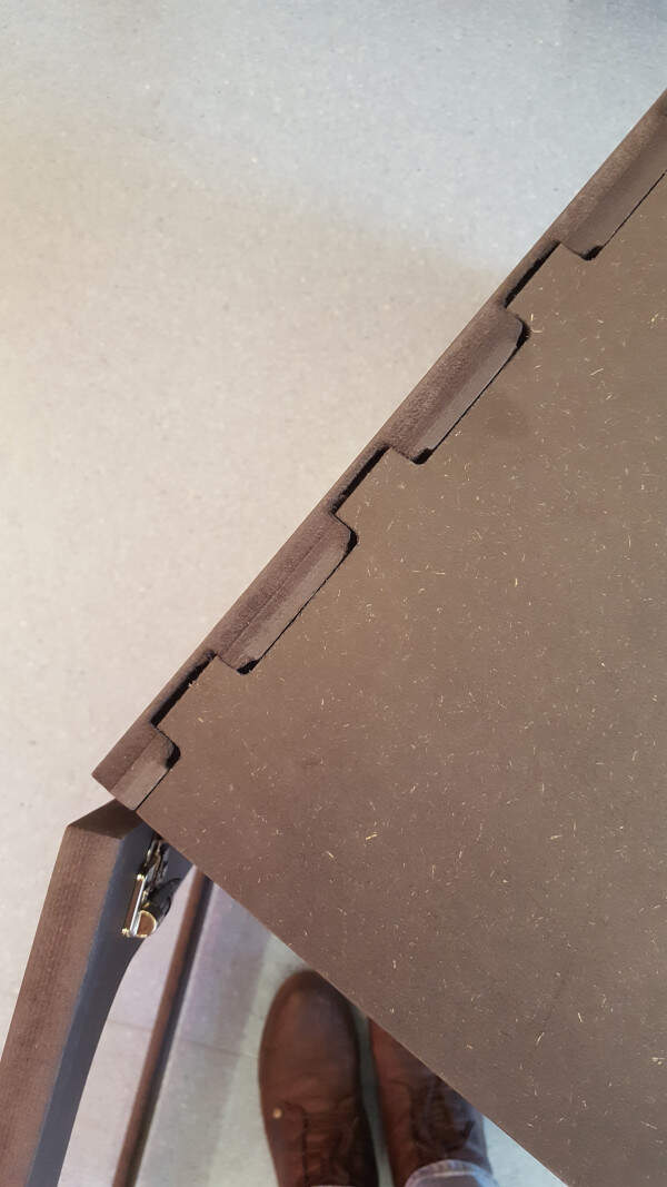
Defect on the lateral left panel.
Files
I do not recommend to use the nc files provided here on your own CNC machine. Instead you can use the CAD files and generate your own nc-files or GCODE.