create your own integrated design
demonstrate 2D & 3D modelling capabilities applied to your own designs
select and apply appropriate additive and subtractive techniques
demonstrate competence in design, fabrication and programming of your own fabbed microcontroller PCB, including an input & output device
made your slide: 1280 x 1024 pixels with your name, project name, Fab Lab name, a photo/render/sketch of your project, a brief description of what your project is/does
made a ~1 minute (10MB/1080p/720p) video of you explaining your project
made a separate Final Project page that briefly summarises your project and
included the BOM (Bill of Materials) for your project
linked from this page to any weeks that you worked on your final project
linked to your presentation.png and presentation.mp4
included all of your original design files in the archive (2D & 3D, board files & code) No external hosting of final project files - discuss file sizes with your instructor
included the licence you chose
acknowledged work done by others

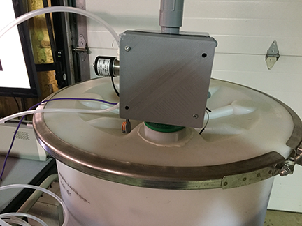
I finally finished my project. The project utilizes a 3-D printed component which can be mounted to any standard PVC junction box, so it can be incorporated into facilities which will require this type of configuration. Please view my presentation page and video here: presentation.png and presentation.mp4. I incorporated and demonstrated mastery of the folowing skillsets with this project:
My original concept was to make a board which would purge a wine tank. Later on, the concept changed in a couple of different ways. First, I discovered CBAmods, which is a great help in being able to rapidly prototype an application. I have been exploring some of the projects using CBAmods at MIT/CBA, and it has changed the way I think about application proogramming for microcontrollers. Neil's mods project lets you interface different components in a distributed way, which has lots of advantages.
Another thing changed along the way. I have a background in ASME pressure vessel design. After embedding myself into the design of the components, I realized that if there was a failure in a sensor, board or other component, it could lead to overpressurization and disaster. Therefore, I modified the concept so that human intervention would be necessary, and that the human would want some sort of feedback if they were operating the device remotely.
After completing networking and communication (week15), I had a clearer idea what my final project would do. When you make wine, there are operations which may be necessary which cause air to be introduced into the wine tank. Air, or more specifically, oxygen, causes wine to spoil and creates wine faults. In order to explain the utility of my device, I must first explain some winemaking basics, and at what stages the device becomes useful.
Air inside of a fermentation tank is not much of an issue, because the tanks are usually filled nearly to the top with juice, and the remaining air in the tank helps the yeast get started. Once fermentation is started, the yeast consume all of the oxygen available, and then once all oxygen is consuimed, the yeast start to metabolize sugar into carbon dioxide and alchohol.
Once fermentation is complete, the dead yeast is allowed to settle to the bottom of the tank. Next, the wine is racked off, where the clarified wine is either siphoned or pumped leaving the dead yeast behind. The racked wine must be placed into a second container. This container is usually of equal size to the first container, and is full of air. There is usually a reduction of volume of 10% due to the sediment left behind. This "headspace" affects wine quality during aging. Some winemakers will take the trouble to purge the space with carbon dioxide or food grade nitrogen. Having a device which can measure oxygen level during purging is beneficial because you are no longer guessing. Furthermore, you can monitor during the aging process with the same device.
Simple device which replaces the traditional air-lock on a wine storage vessel. Must have the ability to monitor oxygen level and control flow of nitrogen gas, programmable, and remotely accessable. Skillsets used in this design are communications and networking, computer-aided design, 3-D printing, electronics production, output device, input device, application programming.
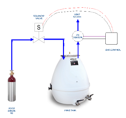
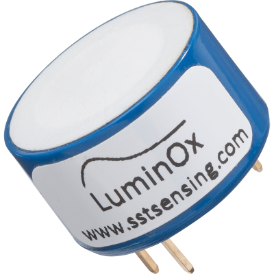
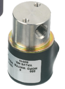
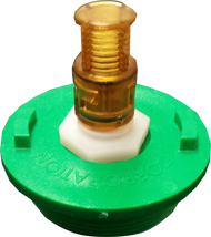
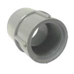
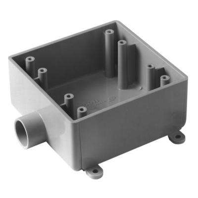
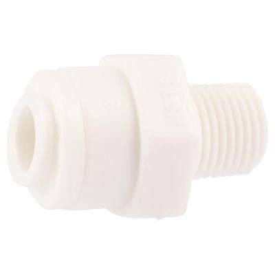
Components which are not in the FabLab inventory which were required for this project. Bill of material total does not include wine, wine storage tank, food-grade argon gas bottle, or regulator. These items are site specific depending upon winery location:
The Hello-Solenoid board is a descendant from the project we did on week8. This is a better version which addresses some of the failures of the earlier project. Designed using Eagle version 7.70 (Mac).
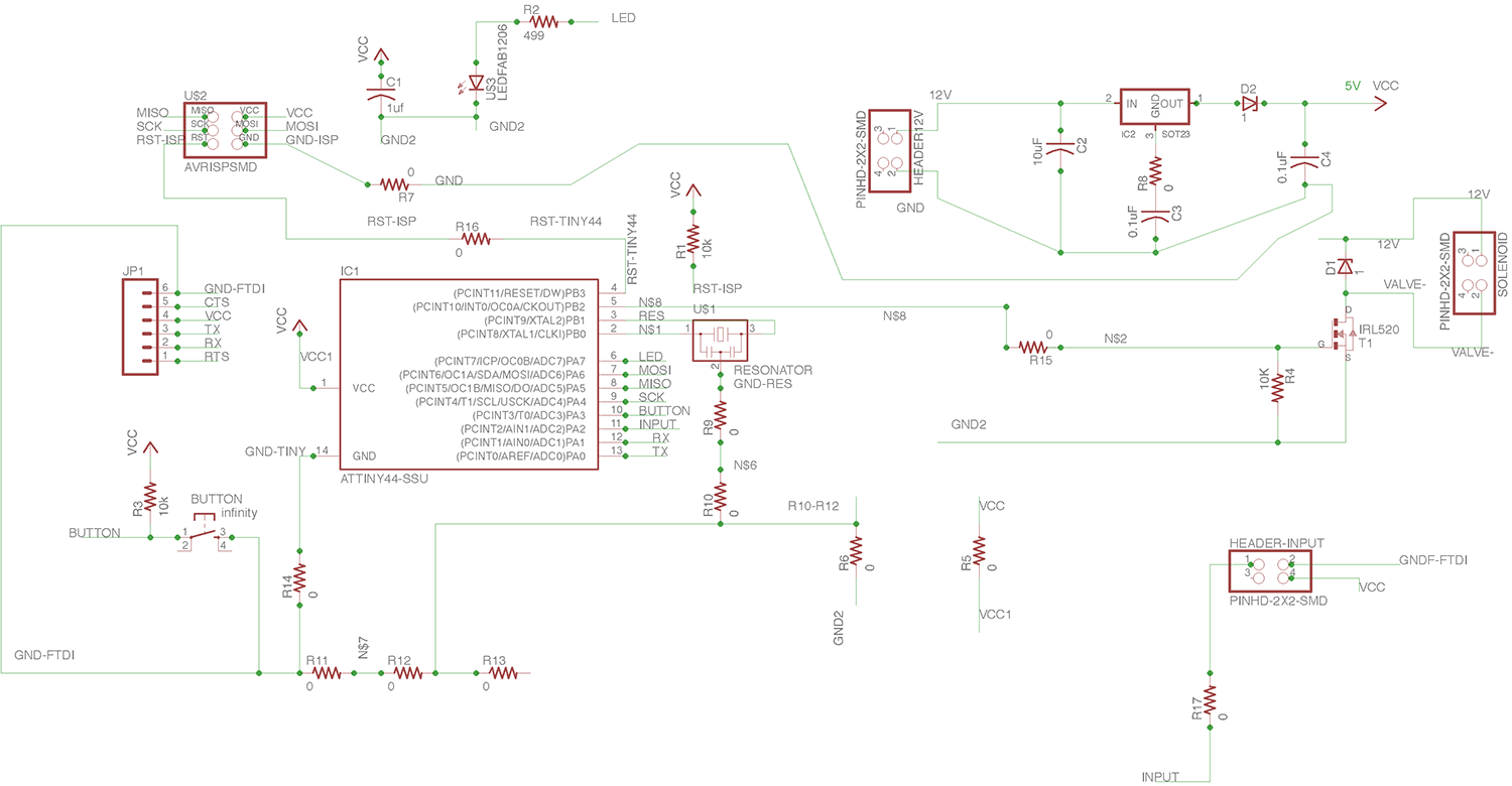
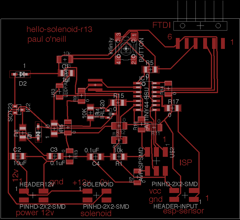
This is different that Solenoid Board Version 12, because it includes header to connect this board to ESP module.
('id=BOM-solenoid')
| Qty | Value | Device | Package | Parts | Description | |
| 1 | M06SMD | 1X06-SMD | JP1 | Header 6 | ||
| 5 | 0 | R-US_R1206 | R1206 | R5, R6, R8, R15, R17 | RESISTOR, American symbol | |
| 8 | 0 | RES-US1206FAB | R1206FAB | R7, R9, R10, R11, R12, R13, R14, R16 | Resistor (US Symbol) | |
| 2 | 0.1uF | CAP-US1206 | C1206 | C3, C4 | ||
| 2 | 1 | ZENER_DIODESOD123 | SOD123 | D1, D2 | zener diode | |
| 1 | 10K | RES-US1206 | R1206 | R4 | Resistor (US Symbol) | |
| 1 | 10k | R-US_R1206 | R1206 | R1 | RESISTOR, American symbol | |
| 1 | 10k | RES-US1206FAB | R1206FAB | R3 | Resistor (US Symbol) | |
| 1 | 10uF | CAP-US1206 | C1206 | C2 | ||
| 1 | 1uf | C-USC1206 | C1206 | C1 | CAPACITOR, American symbol | |
| 1 | 499 | RES-US1206FAB | R1206FAB | R2 | Resistor (US Symbol) | |
| 1 | ATTINY44-SSU | ATTINY44-SSU | SOIC14 | IC1 | ||
| 1 | AVRISPSMD | AVRISPSMD | 2X03SMD | U$2 | ||
| 1 | IRL520 | NMOSFETSOT23 | SOT-23 | T1 | MOS FET | |
| 1 | LEDFAB1206 | LEDFAB1206 | LED1206FAB | U$3 | LED | |
| 3 | PINHD-2X2-SMD | PINHD-2X2-SMD | 2X02SMD | HEADER-INPUT, HEADER12V, SOLENOID | ||
| 1 | RESONATOR | RESONATOR | EFOBM | U$1 | ||
| 1 | SOT23 | REGULATORSOT23 | SOT23 | IC2 | ||
| 1 | infinity | 6MM_SWITCH6MM_SWITCH | 6MM_SWITCH | BUTTON | OMRON SWITCH |
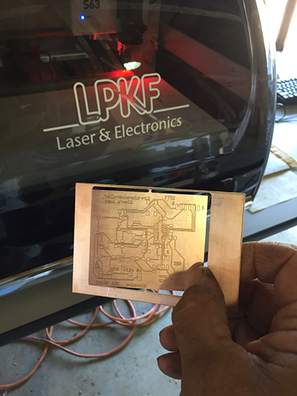
Convert Eagle file to Gerber file and cut on my LPKF board mill.
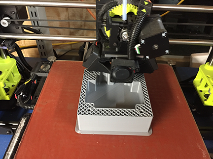
3-D Print hello-solenoid case on my 3-D printer. (file)
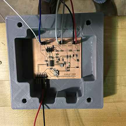
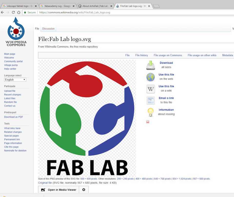
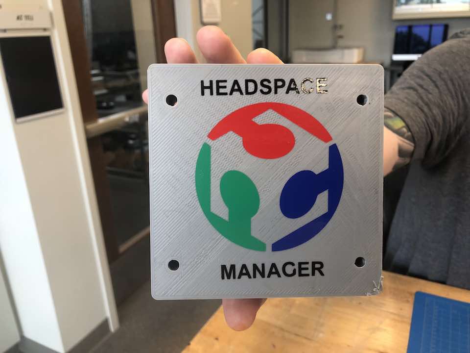
Hello-solenoid installed into case. The 3D printed enclosure case looks too much like a PVC case. Having a nice FabLab logo and a headline would look nice. Since I do not own a vinyl cutter, I took a trip to Lorian in order to use their Roland vinyl cutter. While I was at the lab at Loarian, I thought they might have a logo file kicking around. Turns out the one they had I didn't like, so I started by going on line looking for one. I found what I needed at Wikimedia Commons.
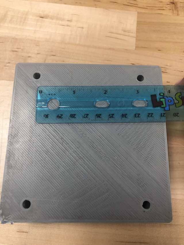
I measured my enclosure so I would know the correct layout for the document.
I downloaded the file and imported it in CorelDraw. I removed the FABLAB logo and added my own logo. I used thre colors of vinyl: red, blue and green. I also used black vinyl. I suppose black is a color also. I selected everything to be hairline so it would plot correctly on the Roland.
CorelDraw files for Vinyl Decal: fab-lab-logo-headspace-manager.zip
I weeded out what I wanted to apply from the different color sheets and assembled it on a mask.
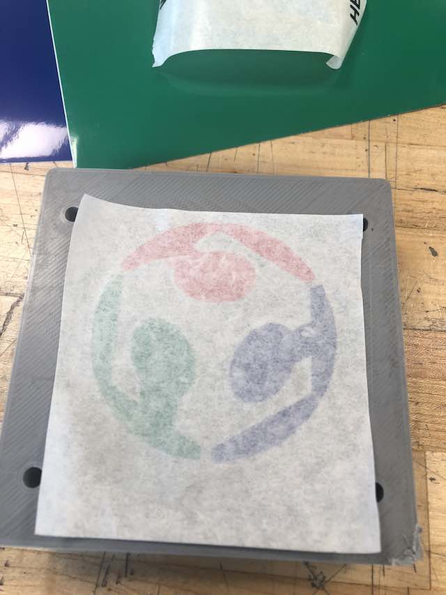
Next, I rubbed down the decal so it would stiock to the 3D printed enclosure.
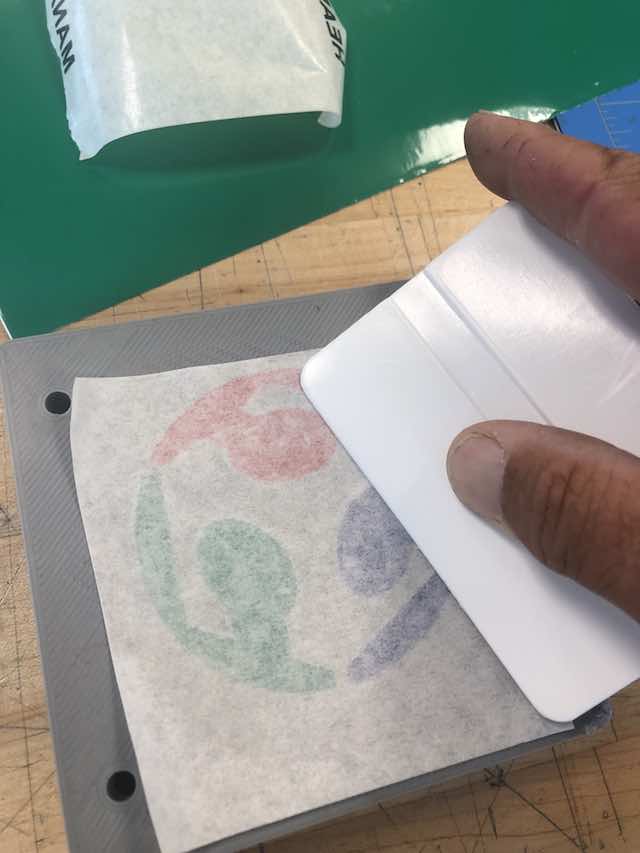
Next, I weeded out the headline for the device and applied the black vinyl in the same fashion.
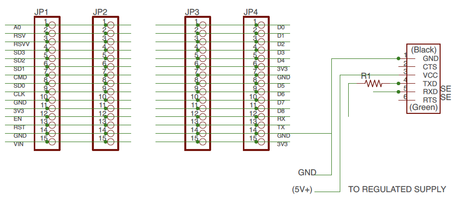
Note: Resistor R1 is a zero-ohm jumper.
('id=BOM-nodeMCU')
| Qty | Value | Device | Package | Parts | Description | |
| 4 | PINHD-1X15 | 1X15 | JP1, JP2, JP3, JP4 | PIN HEADER | ||
| 1 | RES-US1206FAB | R1206FAB | R1 | Resistor (US Symbol) | ||
| 1 | FTDI-SMD-HEADER | FTDI-SMD-HEADER | 1X06SMD | SENSOR |
|
| 1 | MCM Electronics Arduino Shield Stacking Header Kit | Through hole HEADER | $3 from Microcenter |
|
| 1 | HiLetgo 2pcs ESP8266 NodeMCU LUA CP2102 ESP-12E | Purchase two-pack. Use extra for troubleshooting, or share with a friend. | $13 from Amazon |
|
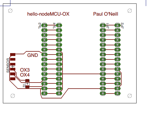
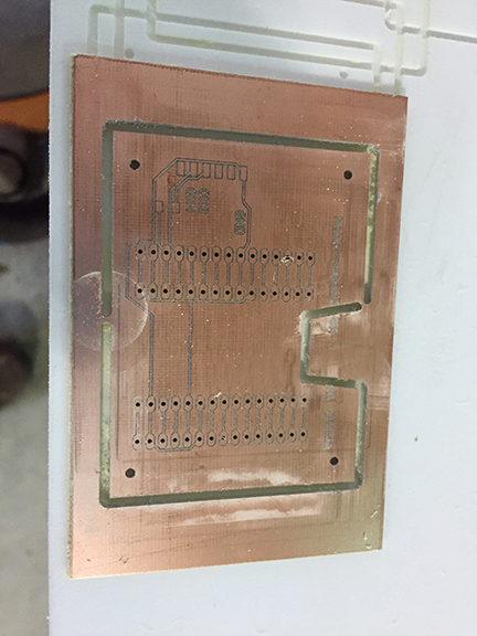
Board engraved and drilled on LPKF mill.
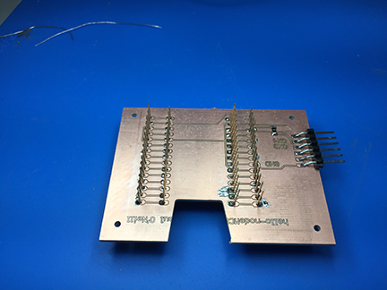
Header pins inserted into drilled holes and soldered. You need 0.80 mm
drill bit to get close tolerance hole for solder to bridge between pin and board.
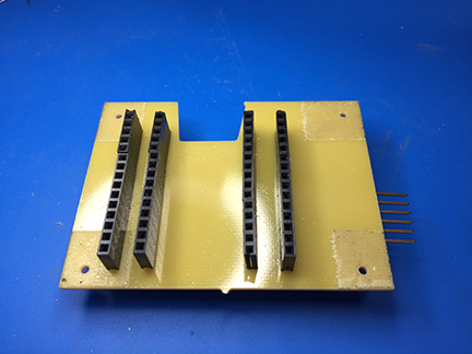
These type of header pins not found in FabLab inventory. You can find them in the Adafruit git repository for Eagle CAD.
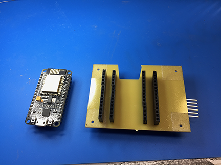
The nodeMCU before insertion intop the shield.
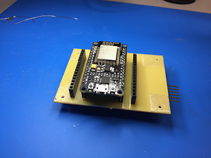
The ESP8266-12 nodeMCU installed into the shield. These can be bought for around $10.
Board programming. I used the Arduino IDE as my programming environment on both a Macbook and a Windows 10 laptop. The Windows10 implementation is easier because COM ports on the Windows machine are easier to tropubleshoot. You must add the esp8266 and ATTiny borads to the environment. You do this from the Arduino IDE main menu by drilling down Arduino - Preferfences - "Additional Boards Manager URL's" box -and click the shadow box to the right, enter the following into two seperate lines in the text box:
http://arduino.esp8266.com/stable/package_esp8266com_index.json
https://raw.githubusercontent.com/damellis/attiny/ide-1.6.x-boards-manager/package_damellis_attiny_index.json
Update: The damellis_attiny_index.json has been having issues. As an alternative, you may need to copy and paste these lines into the ArduinoIDE Additional Boards Manager instead:
http://drazzy.com/package_drazzy.com_index.json
http://arduino.esp8266.com/stable/package_esp8266com_index.json
Then go to Tools - Boards Manager and install esp8266 as well as ATMEL Tiny packages.
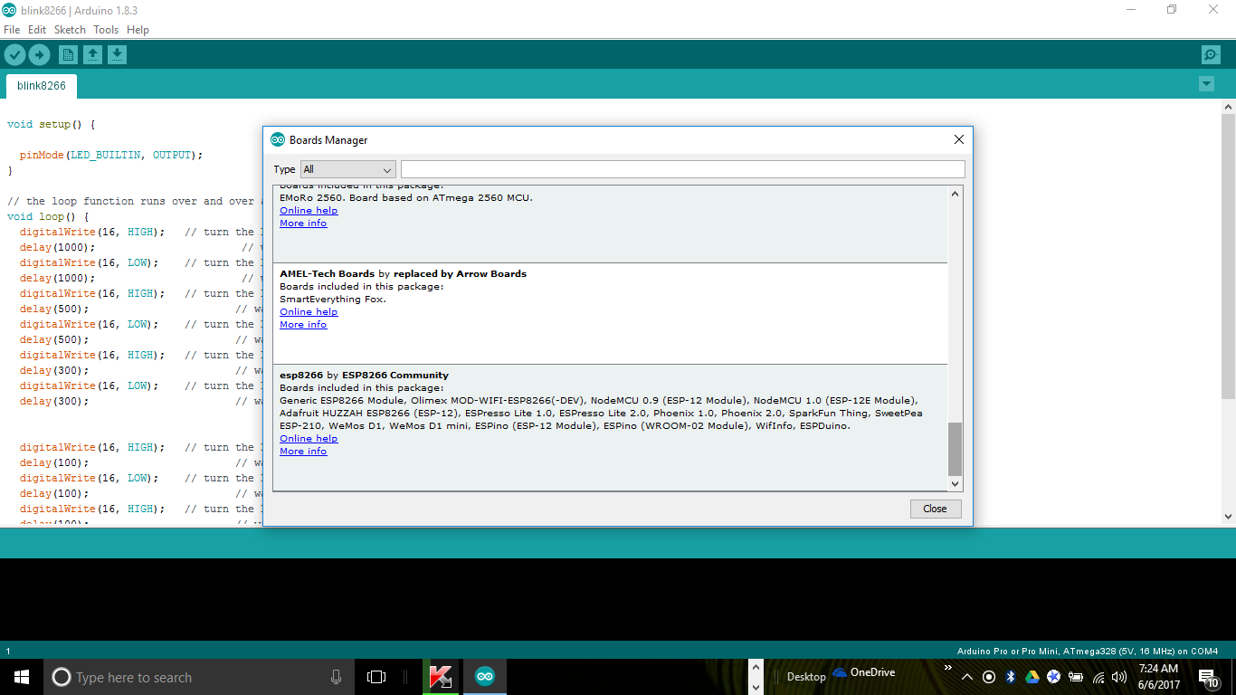
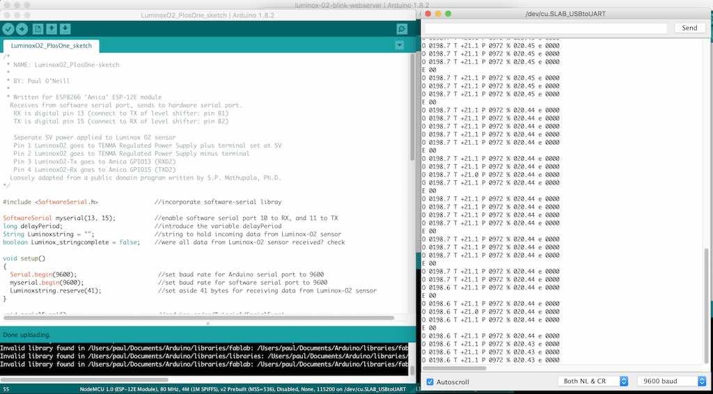
Screenshot of program "LuminoxO2_PlosOne_sketch.ino" monitoring O2 sensor. Output is sent at 9600 baud.
------------------------------------------------BEGIN PROGRAM------------------------------------------------------------
/*
   NAME: LuminoxO2_PlosOne-sketch

   BY: Paul O'Neill

   Written for ESP8266 'Amica' ESP-12E module
  Receives from software serial port, sends to hardware serial port.
   RX is digital pin 13 (connect to TX of level shifter: pin B1)
   TX is digital pin 15 (connect to RX of level shifter: pin B2)

   Seperate 5V power applied to Luminox O2 sensor
   Pin 1 LuminoxO2 goes to TENMA Regulated Power Supply plus terminal set at 5V
   Pin 2 LuminoxO2 goes to TENMA Regulated Power Supply minus terminal
   Pin 3 LuminoxO2-Tx goes to Amica GPIO13 (RXD2)
   Pin 4 LuminoxO2-Rx goes to Amica GPIO15 (TXD2)
  Loosely adapted from a public domain program written by S.P. Mathupala, Ph.D.
*/

#include <SoftwareSerial.h>                //incorporate software-serial libray

SoftwareSerial myserial(13, 15);           //enable software serial port 10 to RX, and 11 to TX
long delayPeriod;                          //introduce the variable delayPeriod
String Luminoxstring = "";                 //string to hold incoming data from Luminox-O2 sensor
boolean Luminox_stringcomplete = false;    //were all data from Luminox-O2 sensor received? check

void setup()
{
  Serial.begin(9600);                       //set baud rate for Arduino serial port to 9600
  myserial.begin(9600);                     //set baud rate for software serial port to 9600
  Luminoxstring.reserve(41);                //set aside 41 bytes for receiving data from Luminox-O2 sensor
}

void serialEvent()                          //arduino.cc/en/Tutorial/SerialEvent
{
  delayPeriod = 1000;
  String inchar = "";                      //setup a string to hold incoming char
  while (Serial.available() > 0) {         //when a char is avaialble in serial buffer
    inchar += (char)Serial.read();        //grab that char
    //      if (inchar == "m")                    //if the char is a "m"
    //      delayPeriod = 300000;                 //set delay period to 5 minutes (300000 milli seconds)
    if (inchar == "s")                    //if char is a "s"
      delayPeriod = 1000;                   //set delay period to 1 second (1000 milli seconds)
  }
}

void loop()
{
  { // Serial.print(".");                                          //start the loop sequence
    while (myserial.available()) {            //when a char is avaialable in software serial buffer
      char inchar = (char)myserial.read();    //grab that char
      Luminoxstring += inchar;                //add the received char to LuminoxString
      if (inchar == '\r') {                   //if the incoming character is a <term>, reset
        Luminox_stringcomplete = true;        //then a complete string of data has been recieved from Luminox-O2 sensor
      }
    }

    if (Luminox_stringcomplete) {              //has a complete string from the Luminox sensor has been received?
      Luminoxstring.remove(80);                //remove any serial string overruns between reads
      Serial.print(Luminoxstring);             //use the Arduino serial port to send that data to CoolTerm
      Luminoxstring = "";                      //then clear the Luminoxstring:
      Luminox_stringcomplete = false;          //await the next data string from Luminox-O2 sensor
      delay(delayPeriod);                      //pause for 5 minutes(300000 millis); or 1 second (1000 millis)
    }
  }
}
--------------------------------------------------------END OF PROGRAM----------------------------------------------------
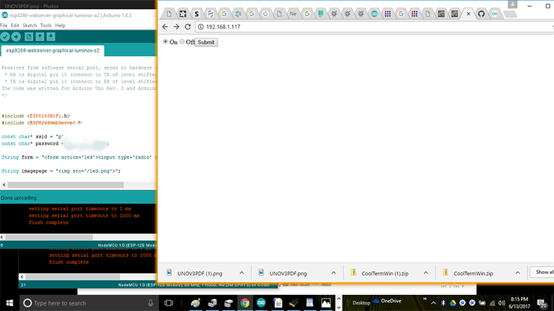
Screenshot of program "esp8266-webserver-graphical-Lumionox-o2" demonstrating graphical user interface connectivity to the solenoid device.
----------------------------------------------------------BEGIN PROGRAM------------------------------------------------------------------------------------------------
/*
  ESP8266 Server program to read Luminox O2 sensor.

  By: Paul O'Neill

  (C) Copyright 2017 by Paul X. O'Neill, All rights reserved.
  This work may be reproduced, modified, distributed, performed, and
   displayed for any purpose, but must acknowledge the author.
   Copyright is retained and must be preserved. The work is
   provided as is; no warranty is provided, and users accept all
   liability.

  Receives from software serial port, sends to hardware serial port.
   RX is digital pin 10 (connect to TX of level shifter: pin B1)
   TX is digital pin 11 (connect to RX of level shifter: pin B2)
  The code was written for hello-nodeMCU and Arduino IDE ver. 1.6.1.

  Adapted from an example program called WiFiWebClient
  included in the Arduino IDE written by dlf (Metodo2 srl)
  and modified by Tom Igoe.

*/


#include <ESP8266WiFi.h>
#include <ESP8266WebServer.h>

const char* ssid = "wf-b";
const char* password = "2627f68597";

String form = "<form action='led'><input type='radio' name='state' value='0' checked>On<input type='radio' name='state' value='1'>Off<input type='submit' value='Submit'></form>";

String imagepage = "<img src='/led.png'>";

// This is a png file (led.png)
const char image[] = {
  0x89, 0x50, 0x4e, 0x47, 0x0d, 0x0a, 0x1a, 0x0a, 0x00, 0x00, 0x00, 0x0d, 0x49, 0x48, 0x44, 0x52,
  0x00, 0x00, 0x00, 0x10, 0x00, 0x00, 0x00, 0x10, 0x08, 0x02, 0x00, 0x00, 0x00, 0x90, 0x91, 0x68,
  0x36, 0x00, 0x00, 0x00, 0x01, 0x73, 0x52, 0x47, 0x42, 0x00, 0xae, 0xce, 0x1c, 0xe9, 0x00, 0x00,
  0x00, 0x04, 0x67, 0x41, 0x4d, 0x41, 0x00, 0x00, 0xb1, 0x8f, 0x0b, 0xfc, 0x61, 0x05, 0x00, 0x00,
  0x00, 0x20, 0x63, 0x48, 0x52, 0x4d, 0x00, 0x00, 0x7a, 0x26, 0x00, 0x00, 0x80, 0x84, 0x00, 0x00,
  0xfa, 0x00, 0x00, 0x00, 0x80, 0xe8, 0x00, 0x00, 0x75, 0x30, 0x00, 0x00, 0xea, 0x60, 0x00, 0x00,
  0x3a, 0x98, 0x00, 0x00, 0x17, 0x70, 0x9c, 0xba, 0x51, 0x3c, 0x00, 0x00, 0x00, 0x18, 0x74, 0x45,
  0x58, 0x74, 0x53, 0x6f, 0x66, 0x74, 0x77, 0x61, 0x72, 0x65, 0x00, 0x50, 0x61, 0x69, 0x6e, 0x74,
  0x2e, 0x4e, 0x45, 0x54, 0x20, 0x76, 0x33, 0x2e, 0x33, 0x36, 0xa9, 0xe7, 0xe2, 0x25, 0x00, 0x00,
  0x00, 0x57, 0x49, 0x44, 0x41, 0x54, 0x38, 0x4f, 0x95, 0x52, 0x5b, 0x0a, 0x00, 0x30, 0x08, 0x6a,
  0xf7, 0x3f, 0xf4, 0x1e, 0x14, 0x4d, 0x6a, 0x30, 0x8d, 0x7d, 0x0d, 0x45, 0x2d, 0x87, 0xd9, 0x34,
  0x71, 0x36, 0x41, 0x7a, 0x81, 0x76, 0x95, 0xc2, 0xec, 0x3f, 0xc7, 0x8e, 0x83, 0x72, 0x90, 0x43,
  0x11, 0x10, 0xc4, 0x12, 0x50, 0xb6, 0xc7, 0xab, 0x96, 0xd0, 0xdb, 0x5b, 0x41, 0x5c, 0x6a, 0x0b,
  0xfd, 0x57, 0x28, 0x5b, 0xc2, 0xfd, 0xb2, 0xa1, 0x33, 0x28, 0x45, 0xd0, 0xee, 0x20, 0x5c, 0x9a,
  0xaf, 0x93, 0xd6, 0xbc, 0xdb, 0x25, 0x56, 0x61, 0x01, 0x17, 0x12, 0xae, 0x53, 0x3e, 0x66, 0x32,
  0xba, 0x00, 0x00, 0x00, 0x00, 0x49, 0x45, 0x4e, 0x44, 0xae, 0x42, 0x60, 0x82
};

// HTTP server will listen at port 80
ESP8266WebServer server(80);

const int solenoid = 16;  //ESP-12 pin1, D0, GPIO 16
const int led = 4;        //ESP-12 pin3, D2, GPIO 4

void handle_adc() {
  float val = analogRead(0);
  server.send(200, "text/plain", String(val));
}

void handle_led() {
  // get the value of request argument "state" and convert it to an int
  int state = server.arg("state").toInt();

  digitalWrite(led, state);
  digitalWrite(solenoid, state);
  server.send(200, "text/plain", String("LED is now ") + ((state) ? "off" : "on"));
}

void handle_image() {
  server.send(200, "image/png", "");
  WiFiClient client = server.client();
  client.write(image, sizeof(image));
}

void handle_webpage_with_image() {
  server.send(200, "text/html", imagepage);
}

void setup(void) {
  Serial.begin(9600);
  Serial.println("");
  pinMode(led, OUTPUT);
  pinMode(solenoid, OUTPUT);

  // Connect to WiFi network
  WiFi.begin(ssid, password);

  // Wait for connection
  while (WiFi.status() != WL_CONNECTED) {
    delay(500);
    Serial.print("-SOLENOID TEST-");
    digitalWrite(solenoid, HIGH);   // turn the SOLENOID on (HIGH is the voltage level)
    delay(1000);                       // wait for a second
    digitalWrite(solenoid, LOW);    // turn the SOLENOID off by making the voltage LOW
    delay(1000);                       // wait for a second
    digitalWrite(solenoid, HIGH);   // turn the SOLENOID on (HIGH is the voltage level)
    delay(1000);                       // wait for a second
    digitalWrite(solenoid, LOW);    // turn the SOLENOID off by making the voltage LOW
    delay(1000);                       // wait for a second
    digitalWrite(solenoid, HIGH);   // turn the SOLENOID on (HIGH is the voltage level)
    delay(1000);                       // wait for a second
    digitalWrite(solenoid, LOW);    // turn the SOLENOID off by making the voltage LOW
    delay(1000);                       // wait for a second
  }
  Serial.println("");
  Serial.print("Connected to ");
  Serial.println(ssid);
  Serial.print("IP address: ");
  Serial.println(WiFi.localIP());

  // Set up the endpoints for HTTP server
  //
  // Endpoints can be written as inline functions:
  server.on("/", []() {
    server.send(200, "text/html", form);
  });

  // And as regular external functions:
  server.on("/adc", handle_adc);
  server.on("/led", handle_led);
  server.on("/led.png", handle_image);
  server.on("/showled", handle_webpage_with_image);

  // Start the server
  server.begin();
  Serial.println("HTTP server started");
}

void loop(void) {
  // check for incomming client connections frequently in the main loop:
  server.handleClient();
}
----------------------------------------------------------------------END PROGRAM------------------------------------------------------------------------------------
It is easy for something to not be communicating correctly, or connected incorrectly. I found this program to be very helpful when I thought something was wrong. This is basically a BLINK program for the solenoid board.
------------------------------------------------------BEGIN PROGRAM---------------------------------------------------------------------
#include <SoftwareSerial.h>

/*
  HELLO-SOLENOID-ESP

  by Paul O'Neill
  Modified from example in the Arduino IDE.  Contributing authors noted below.

  Turns on an LED on for one second, then off for one second, repeatedly.

  Most Arduinos have an on-board LED you can control. On the UNO, MEGA and ZERO
  it is attached to digital pin 13, on MKR1000 on pin 6. LED_BUILTIN is set to
  the correct LED pin independent of which board is used.
  If you want to know what pin the on-board LED is connected to on your Arduino model, check
  the Technical Specs of your board  at https://www.arduino.cc/en/Main/Products

  This example code is in the public domain.

  modified 8 May 2014
  by Scott Fitzgerald

  modified 2 Sep 2016
  by Arturo Guadalupi

  modified 8 Sep 2016
  by Colby Newman
*/


const int LED = 7;  //TINY44 PA7
const int SOLENOID = 8;     //TINY44 PB2, IDE 8, pin 5
const int ESP = 2;  //TINY44 PA2, IDE 2, pin 11
const int BUTTON = 3;     //TINY44 button connected to PA3, IDE 3, pin 10


// the setup function runs once when you press reset or power the board
void setup() {
  // initialize digital pin LED_BUILTIN as an output.

  pinMode(LED, OUTPUT);
  pinMode(SOLENOID, OUTPUT);
  pinMode(ESP, INPUT);
  pinMode(BUTTON, INPUT);

  //  Serial.begin(9600);
}

// the loop function runs over and over again forever
void loop() {

  int ESPValue = digitalRead(ESP);
  //  Serial.println(ESPValue);
  if (ESPValue > 0) {
    delay(1);                   // delay added to debounce pin
    digitalWrite(LED, HIGH);
    //digitalWrite(INPUTLINE, HIGH);
    digitalWrite(SOLENOID, HIGH);
  } else {
    digitalWrite(LED, LOW);    // turn the LED off by making the voltage LOW
    digitalWrite(SOLENOID, LOW);

    /*
       The code below left in for troubleshooting purposes.

      digitalWrite(LED, HIGH);   // turn the LED on (HIGH is the voltage level)
      //  digitalWrite(INPUTLINE, HIGH);
      digitalWrite(SOLENOID, HIGH);
      delay(2500);                       // wait for 2500 millseconds
      digitalWrite(LED, LOW);    // turn the LED off by making the voltage LOW
      //  digitalWrite(INPUTLINE, LOW);
      digitalWrite(SOLENOID, LOW);
      delay(1000);                       // wait for 1000 milliseconds

    */
  }
}
-----------------------------------------------------END PROGRAM----------------------------------------------------------------------
During week15, I demonstrated connecting the solenoid board to CBAmods through the FTDI connector.
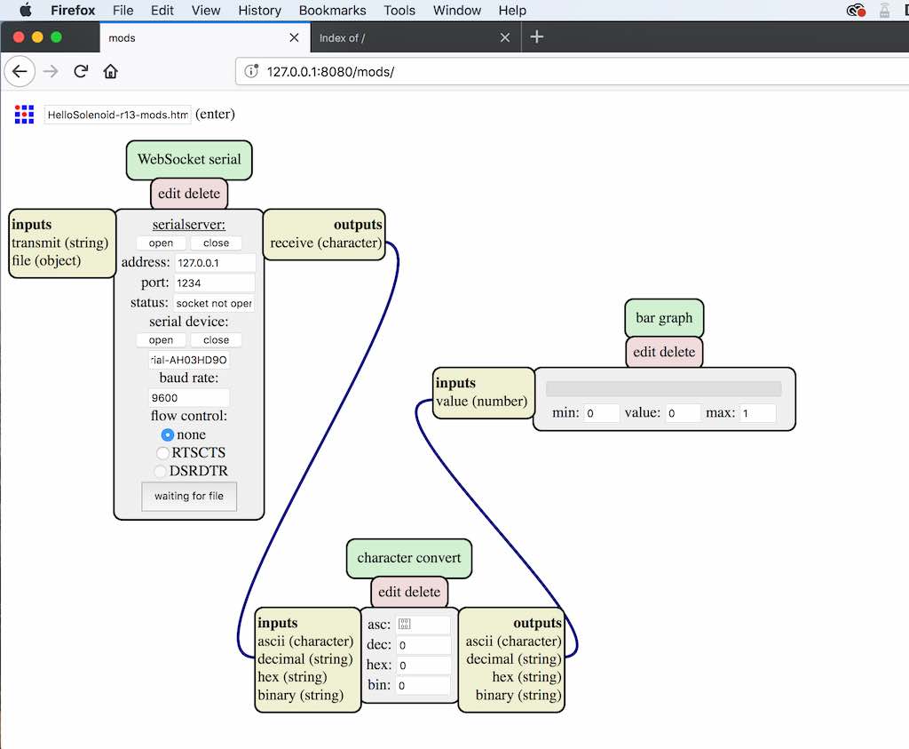
I shared the above CBAmods program during week15. Here is a link to make it easier for you to find. Follow my procedure in week15 on how to do CBAmods. It even works on the HelloWorld board: HelloSolenoid-r13-mods.html
I'm not really sure if I shoud be calling the above a program. It is a HTML file containing javascript which is operated by a Terminal window which is running the mods server. Probably better if Prof. Gershenfeld explain it. I'm still learning CBAmods. I really like it.
I integrated the parts together for my Final Project using CBAmods and ArduinoIDE. The boards used for the final integration are the helloSolenoid Version 13, and the helloNodeMCU board. The solenoid board is the result of spiral development of the original Hello-World board whioch was part of our early lesson. It began with the ATTiny44 module until it couldn't grow any more. Then I had to step up to something bigger, which is an Espressif-based development module based on the ESP-12E. I programmed sketches into each board with the ArduinoIDE, and later on spiraling back to each board applying CBAmods. The software for everything here is covered in week15. CBAmods is done real-time on the screen and is pretty simple. The hardest part of CBAmods is trying to save something as a file. Still trying to figure that one out. Here is the result. I hope you like it.
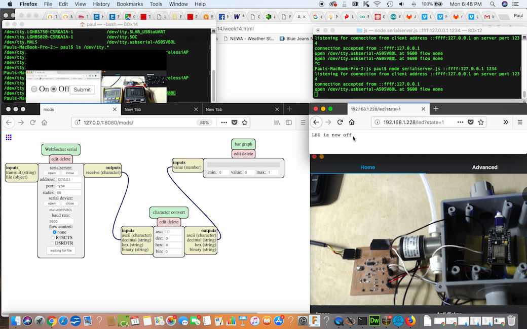
The hello-solenoid board is my 13th revision from Week 8: Output Devices. I used spiral development, utilizing the most basic board we started with, and with each week's lesson, adding onto the board, steering the design towards my final project.
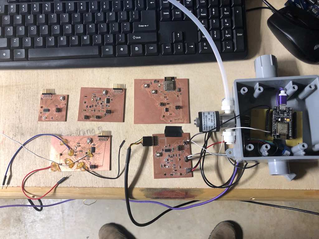
Variations of the hello-world board, starting clockwise from top left:
The voltage regulator from my hello-solenoid rev 8 burned due to being powered from two diffefrent sources. I remidied this on hello-solenoid-r12 and r13 by adding two diodes, and it seemed to do the trick. The 100ma MOFSET seems large enough to drive the coil on my solenoid valve. I used a regulated power supply set at 6 volts, and this seemed adequate for both the solenoid valve and the heating circuit of the Luminox-O2 sensor. I also utilized the micro-USB port on tthe ESP8266-12E to supply 3.3V to the serial connections for the Luminox-O2 sensor. I also made a connection from hello-nodeMCU-OX(JP2:D0) to the hello-solenoid-r13(esp-sensor:1). This allows the program executing on the hello-nodeMCU-OX board to control the solenoid valve which is physically connected to the hello-solenoid-r13 board. Port D0 on the nodeMCU also is special in the fact when you press the reset button on the nodeMCU, it causes the solenoid to open. This is useful for testing purposes. This implementation allows the possibility of controlling the solenoid via WIFI. There is also the possibility of controlling the solenoid valve through the monitoring of the Luminox-O2 sensor.
What to do next? On the hardware side, I would make a power supply board with AC adapter. There is a requirement of the Oxygen sensor that the communication lines be disconnected prior to applying power to pins 1 and 2 for heating. If the O2 sensor is powered before or at the same time as the microcontreoller, it seems to hang the microcontroller. Thus, I would provision the power supply board to time-power each of the boards and sensors in sequence. On the software side, I would clearly define application requirements and then proceed in developing code to meet those requirements. Software architecture is really, really important here. Topics such as "big data", "IOT", and "cloud computing" come to mind, and I feel is beyond the scope of Fabacademy. I thought it was important to simply demomstrate the capabilities of the device and leave application development for later.
Now that the hardware is developed, there is huge potential with software development driving the application development. For instance, this device can be installed on a wine storage tank, and wine sold to a customer can be drawn directly from the main storage tank, and as the wine is drawn, inert gas can automatically be added to the tank to prevent oxygen from getting in. This would require two devices. One device to let nitrogen into the tank. A second device to let wine out of the tank. Another example application would be installing on a tank and have the device run every 2 hours for headspace monitoring. If O2 is out of range, trigger an alarm event. The device could be used for purging empty bottles prior to filling with wine. There are a lot of different ways this hardware can be integrated.
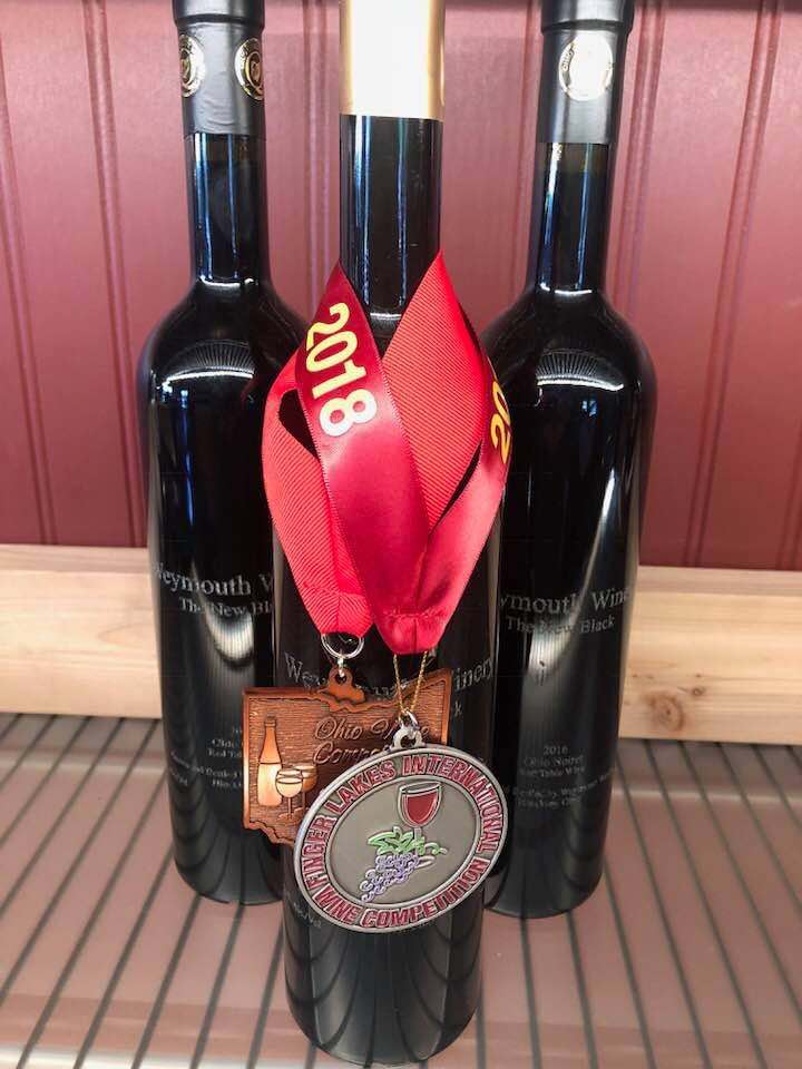
I believe my project is one of the first "Wine Projects" in Fabacademy. The Final Project is mostly electronics controlling a process. I thought it would be appropriate to talk about the "Final Product" in addition to the "Final Project". I used the Final Project on Tank 7 of our wine called "The New Black". The New Black too the Silver Medal at the Finger Lakes International Wine Competition in 2017. This was the first red wine for Weymouth Winery, so we are off to a good start with a little help from the technology developed at the Fabacademy. In addition to using the Headspace Manager, we used our Laser Cutter to engrave the bottles.
Files for Laser Engraving Bottles: TheNewBlack-Engraving-Files.zip
I am currently working on combining the ESP8266-012E and the hello-solenoid all on one board. I may want to install a UART and a micro-USB.
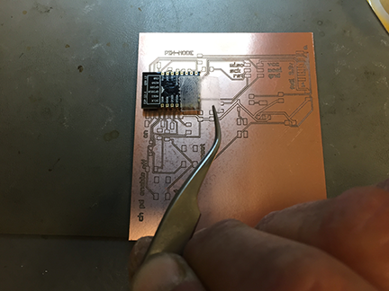
Soldering the ESP8266-12E directly to the board requires using double-stick tape to hold it straight and in place. Even still, very difficult to get the solder to flow. There are Eagle libraries for the modules. However, labels for the pinouts can be all wrong!
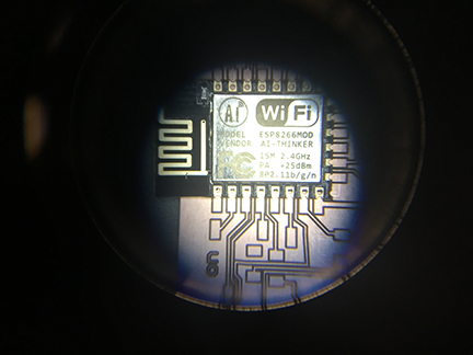
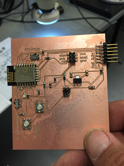
Combining the ESP8266 and the solenoid control on one board eliminates many of the headers and wires. This card is not finished yet. I found it extremely difficult to solder the module to the card. I will need to find someone who can demonstrate to me how to use solder paste. I also found the slide switches to be difficult to solder and rather fragile. I may replace them with surface mount male headers and jumpers. Some of the pins on the ESP8266 need to be connected when being flashed. For a one-time operation, I believe a jumper would be more than adequate.
I have learned that the ESP8266 line of modules require a lot of power. They are very economical. They are difficult to flash. You must read the pinouts of the module because each manufacturer can vary what is where. Building a shield for a particular build of ESP can help in the development process. They are easily bricked, so buy more than one. They are cheap enough. Make sure your data lines are at 3.3V. The module does not tolerate 5V AT ALL! There is also an ESP8266Basic programming language I am experimenting with. I will be evaluating how much resource it provides and how well it works with string data.
I would like to improve the case, possibly making it round, and possibly try some XBee modules next. I would also like to learn more about CBAmods. I noticed that some of the MIT CBA students made modified versions of CBAmods. I would like to learn how to do this, and further improve the integration of the application software so the system is controlled by a server-side application. This fall, after harvest, I hope to have a few of these built and actually try in my winery. I think they will be popular with enologists.
Spiral development!
The author is happy to work with other developers on different applications for this device. Please contact paulxoneill at gmail dot com. I have decided to not openly license the product because I don't believe I have verified well enough if I have infringed on other work, plus I believe this product has some commercial viability as a specialty application, and really won't benefit much from the open-source community. There is some competitive products you can find on Omega Engineering as well as Davis Instruments. Most of these cost in excess of $5000 and do not work quite the same way as my device. You can find out about these at the end of my week20 page.

This work is licensed under a Creative Commons Attribution-NonCommercial-NoDerivatives 4.0 International License.