.png)
Hi! Welcome to Week 14
This week’s assignment was to design, build, and connect wired or wireless node(s) with network or bus addresses.
This week’s assignment was to design, build, and connect wired or wireless node(s) with network or bus addresses.
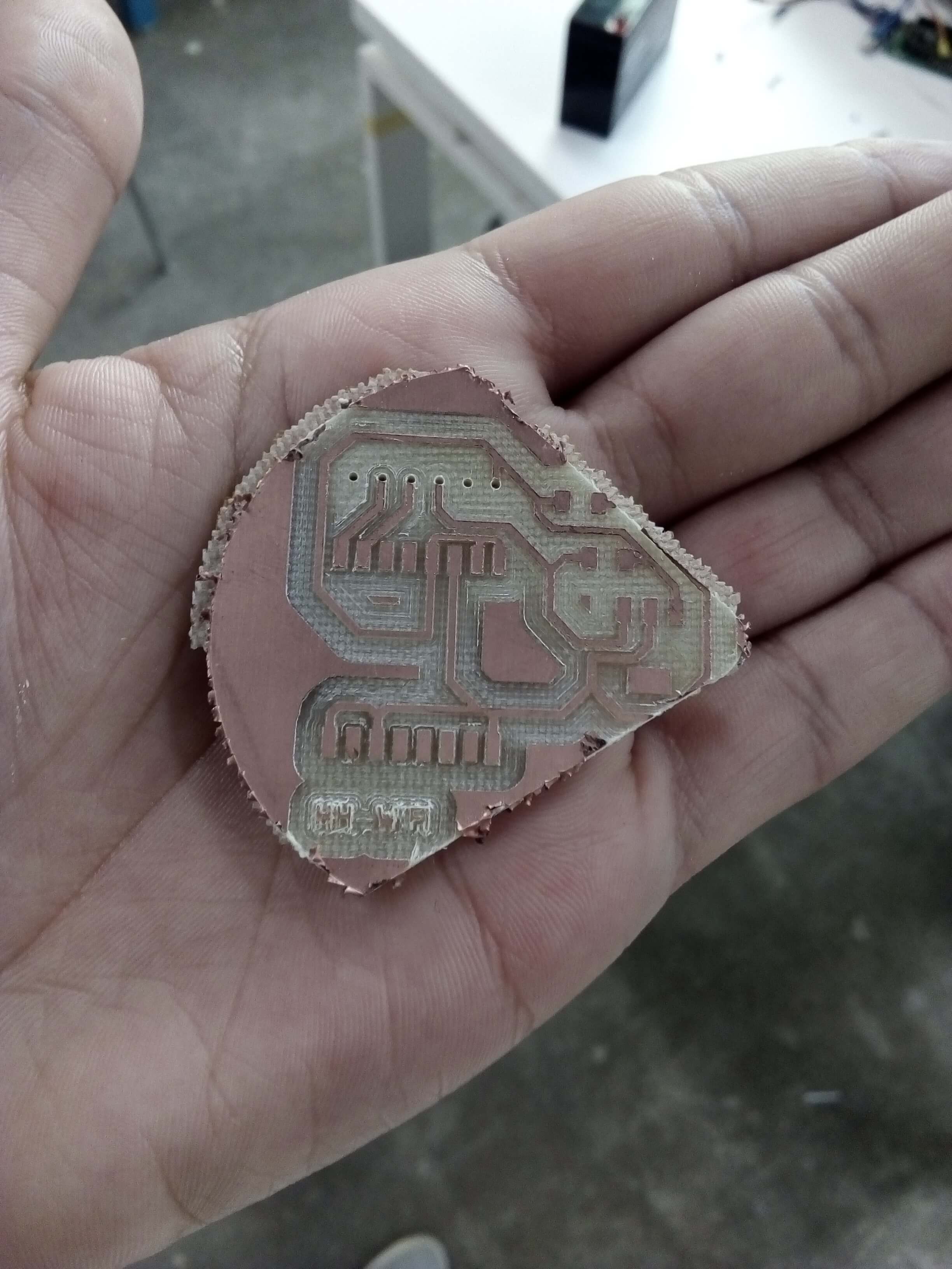
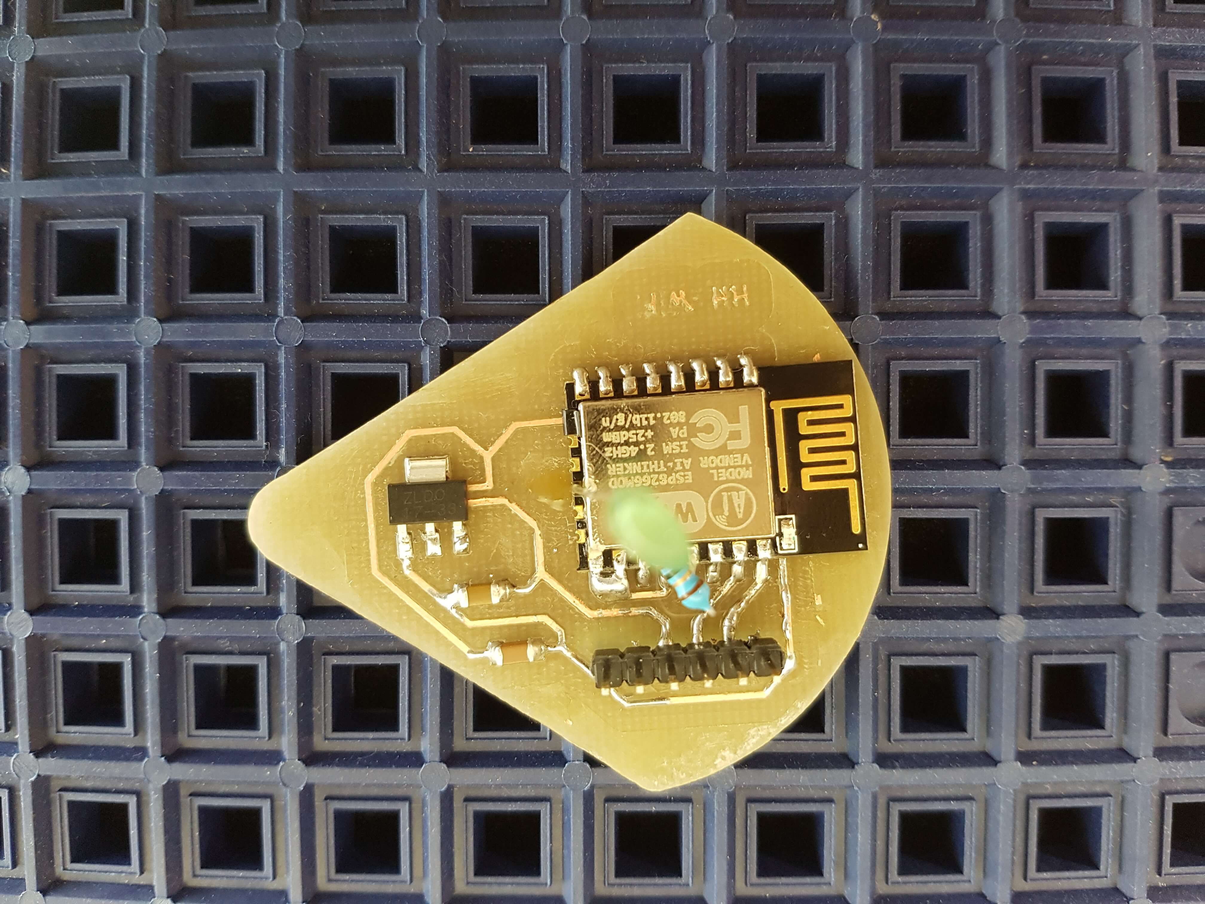
I started this week with the WiFi, I designed my board according to the designs of the previous students in FabAcademy using EAGLE software. For the components, I used:
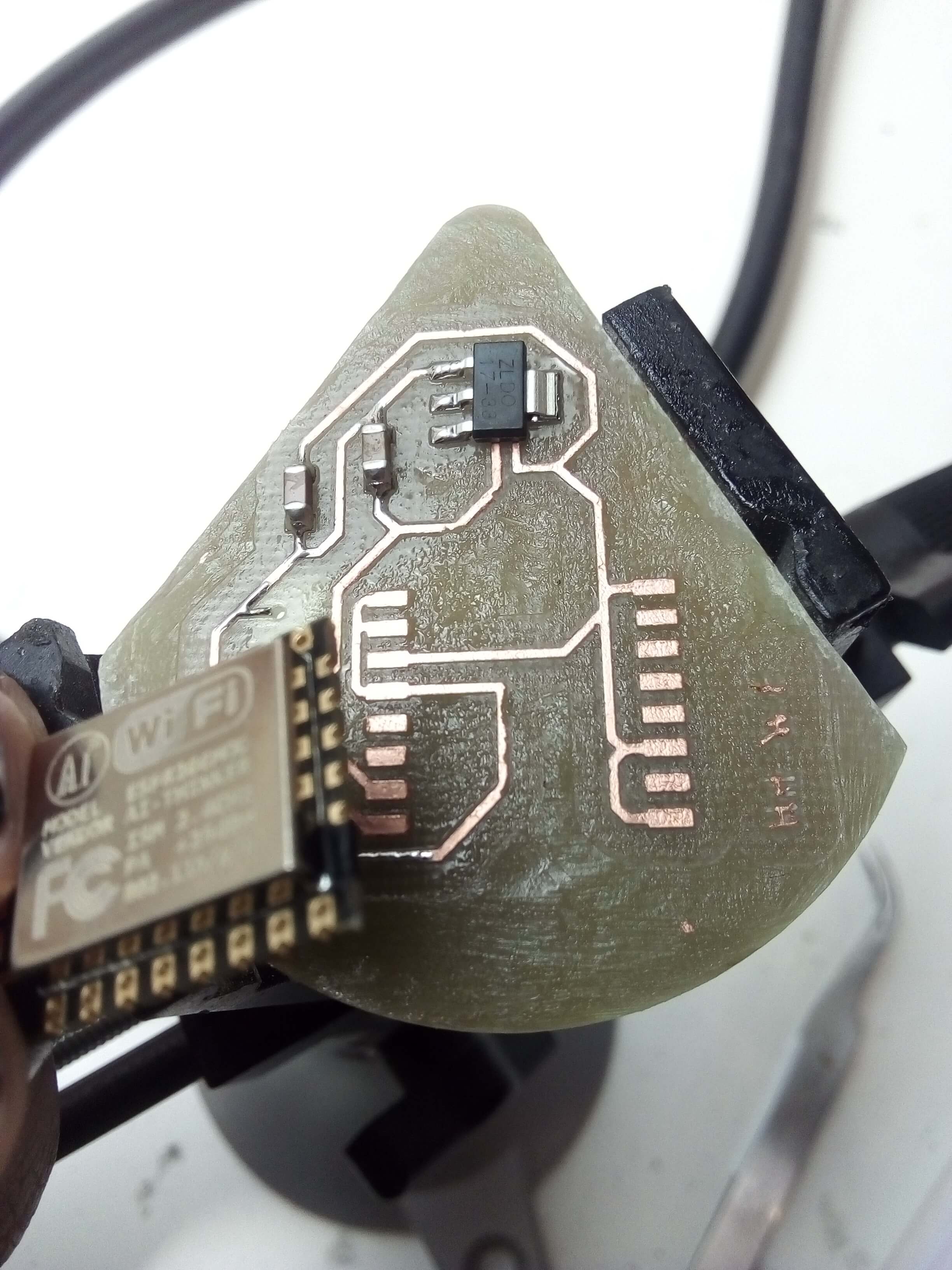
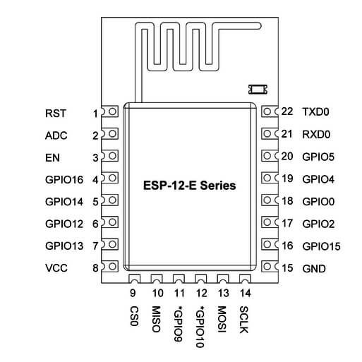
1*ESP8266 12E Module (in the schematics and board, I used ESP07 module, but it was out from the lab so I then used the ESP8266 12E Module as it turned out to have the same dimensions of pins with the exception of one extra side)
1*3.3V voltage regulator
1*FTDI Header (6*Pin headers)
1*1 uF Capacitor 1 uF
1*10 uF Capacitor
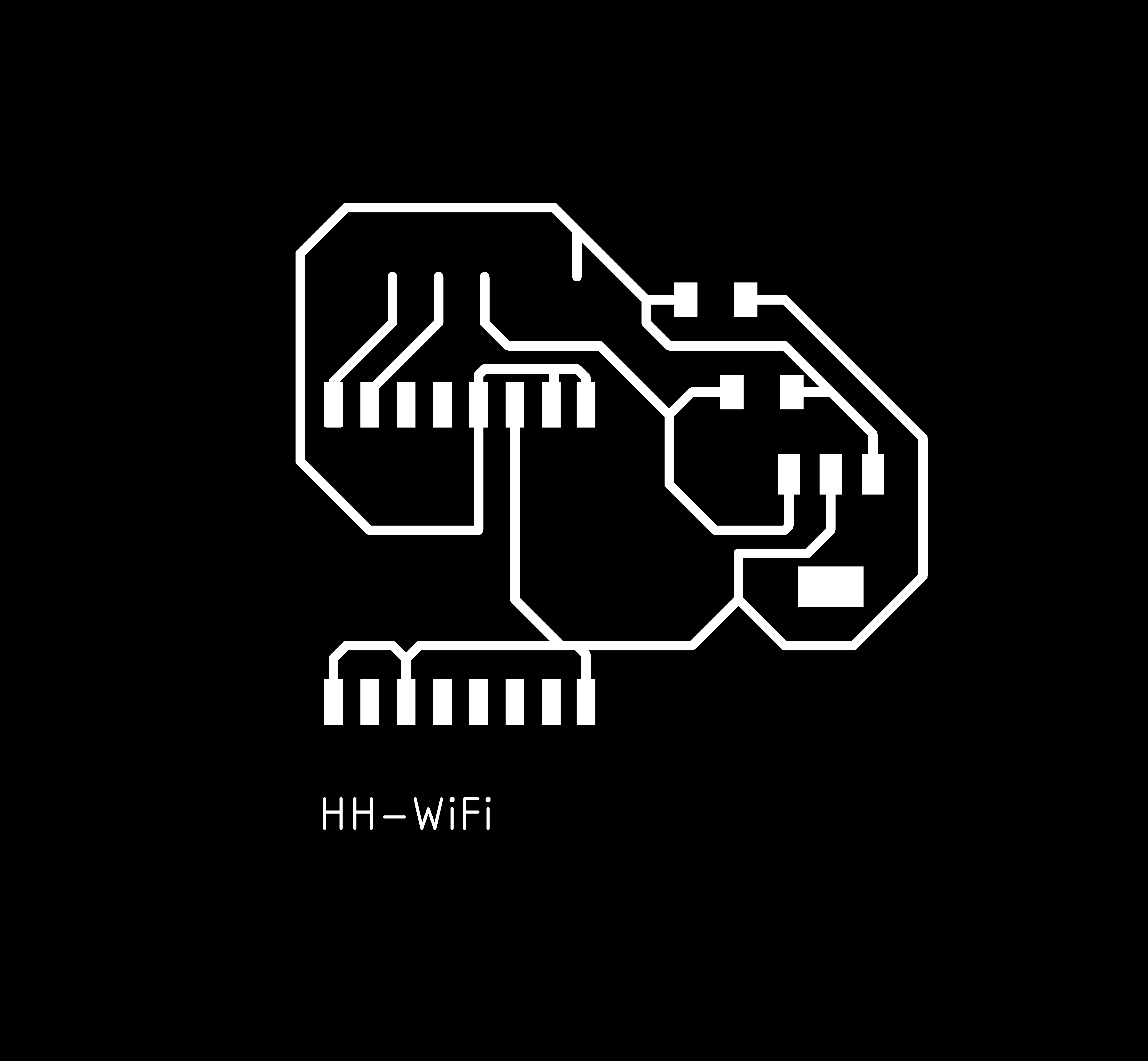


Download the schematics from here, the board from here, or click on any of the images above to download it.
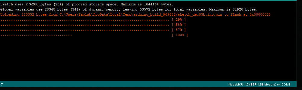
Next, I started soldered the components. And it was ready for programming :D it was easily programmed using the FTDI cable on Arduino, but I had a problem in uploading the program. I spent hours and hours, in the end, the problem was with the computer I was using, I switch to another PC and it uploaded right away. At first, I uploaded an empty program to check the board. I then uploaded a program that would allow me to light an LED on and off, uploaded it and then checked with the multimeter if there was voltage getting to the pin GPIO10, I did. So since I didn’t have an LED on the board when I milled it, I added and LED and an 82 Ohm Resistor to the board, linked it to pin GPIO10 and GND. I then uploaded the program again just to double check, opened the serial monitor, and after few seconds I got the information I wanted on the SM. You can download the program from
here
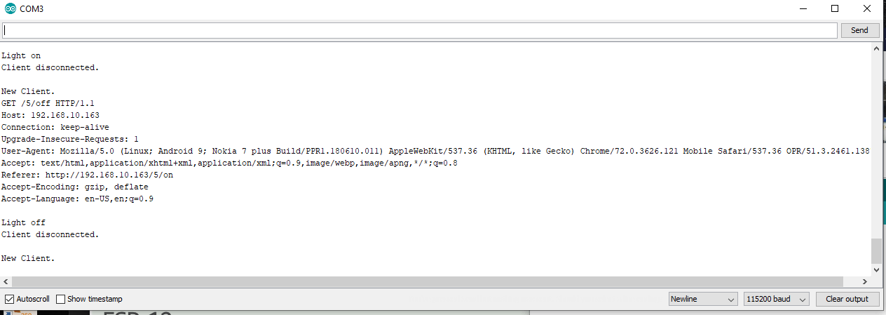
I connected to the same wifi network my module is connected to, and then entered the address I got, and on my phone I could turn on and off the light!
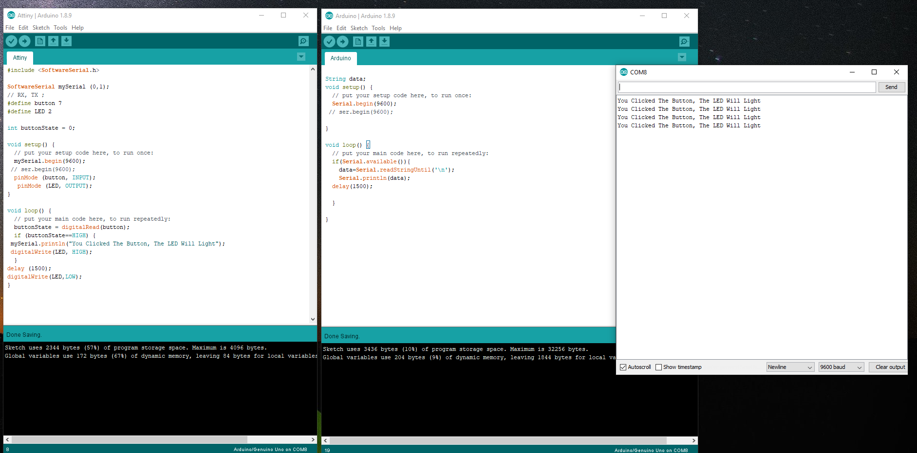
Next up, I tried using Bluetooth to communicate. I had already tried with it several times but it didn’t work, so I took a break from that and then tried again with it, where luckily it worked.
What I did is that I used the board I made few weeks ago, and I uploaded the following program:
/*
  Software serial multple serial test

 Receives from the hardware serial, sends to software serial.
 Receives from software serial, sends to hardware serial.

 The circuit:
 * RX is digital pin 10 (connect to TX of other device)
 * TX is digital pin 11 (connect to RX of other device)

 Note:
 Not all pins on the Mega and Mega 2560 support change interrupts,
 so only the following can be used for RX:
 10, 11, 12, 13, 50, 51, 52, 53, 62, 63, 64, 65, 66, 67, 68, 69

 Not all pins on the Leonardo and Micro support change interrupts,
 so only the following can be used for RX:
 8, 9, 10, 11, 14 (MISO), 15 (SCK), 16 (MOSI).

 created back in the mists of time
 modified 25 May 2012
 by Tom Igoe
 based on Mikal Hart's example

 This example code is in the public domain.

 */
#include   <SoftwareSerial.h>

SoftwareSerial mySerial(11, 12); // RX, TX

void setup() {
  // Open serial communications and wait for port to open:
  Serial.begin(9600);
  while (!Serial) {
    ; // wait for serial port to connect. Needed for native USB port only
  }


  Serial.println("Goodnight moon!");

  // set the data rate for the SoftwareSerial port
  mySerial.begin(9600);
  mySerial.println("Hello, world?");
}

void loop() { // run over and over
  if (mySerial.available()) {
    Serial.write(mySerial.read());
  }
  if (Serial.available()) {
    mySerial.write(Serial.read());
  }
}
#include  <SoftwareSerial.h>

SoftwareSerial mySerial (0,1);
// RX, TX ;
#define button 7
#define LED 2

int buttonState = 0;

void setup() {
  // put your setup code here, to run once:
  mySerial.begin(9600);
 // ser.begin(9600);
  pinMode (button, INPUT);
   pinMode (LED, OUTPUT);
}

void loop() {
  // put your main code here, to run repeatedly:
  buttonState = digitalRead(button);
  if (buttonState==HIGH) {
 mySerial.println("You Clicked The Button, The LED Will Light");
 digitalWrite(LED, HIGH);
  }
delay (1500);
digitalWrite(LED,LOW);
}
String data;
void setup() {
  // put your setup code here, to run once:
  Serial.begin(9600);
 // ser.begin(9600);

}

void loop() {
  // put your main code here, to run repeatedly:
  if(Serial.available()){
    data=Serial.readStringUntil('\n');
    Serial.println(data);
  delay(1500);

  }

}
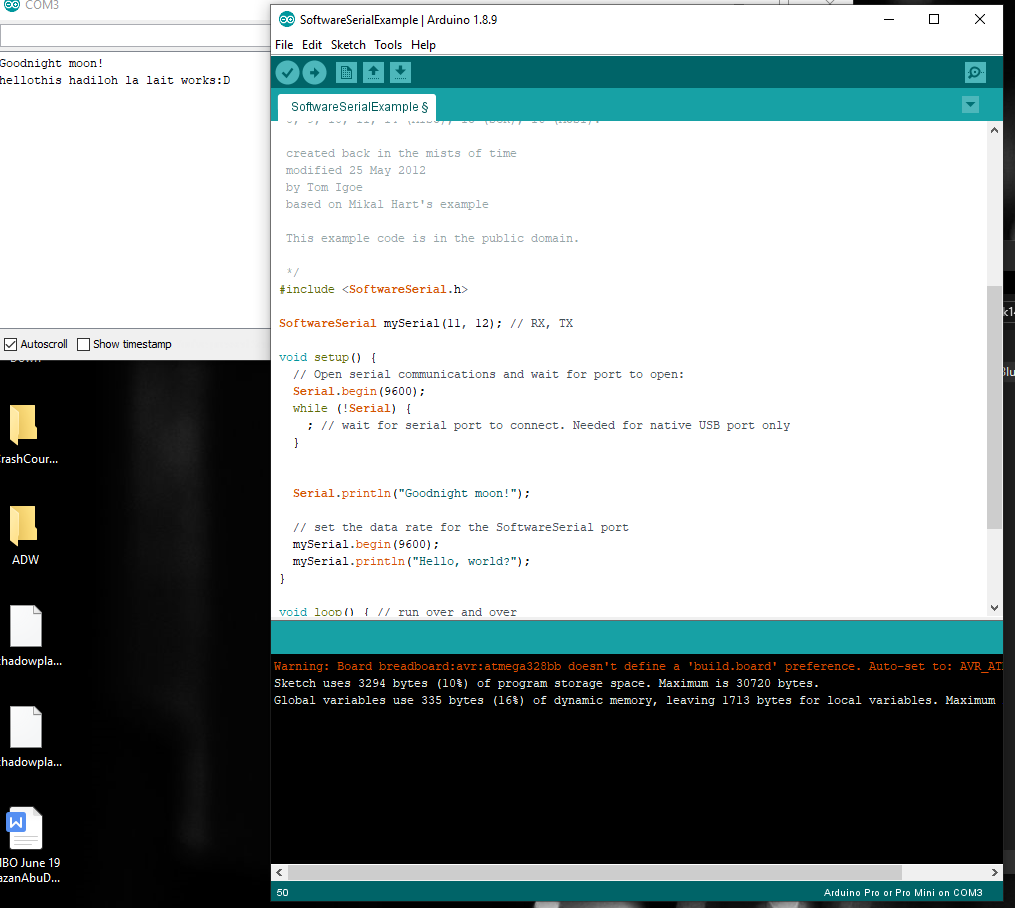
And Then I opened the serial monitor, and it showed nothing :D fortunately, the problem was that I had chosen the wrong baud rate, after changing it in the beginning it started giving reading that was gibberish I tried several rates till I found the one that worked perfectly.
/*
  Software serial multple serial test

 Receives from the hardware serial, sends to software serial.
 Receives from software serial, sends to hardware serial.

 The circuit:
 * RX is digital pin 10 (connect to TX of other device)
 * TX is digital pin 11 (connect to RX of other device)

 Note:
 Not all pins on the Mega and Mega 2560 support change interrupts,
 so only the following can be used for RX:
 10, 11, 12, 13, 50, 51, 52, 53, 62, 63, 64, 65, 66, 67, 68, 69

 Not all pins on the Leonardo and Micro support change interrupts,
 so only the following can be used for RX:
 8, 9, 10, 11, 14 (MISO), 15 (SCK), 16 (MOSI).

 created back in the mists of time
 modified 25 May 2012
 by Tom Igoe
 based on Mikal Hart's example

 This example code is in the public domain.

 */
#include <SoftwareSerial.h>

SoftwareSerial mySerial(11, 12); // RX, TX

void setup() {
  // Open serial communications and wait for port to open:
  Serial.begin(9600);
  while (!Serial) {
    ; // wait for serial port to connect. Needed for native USB port only
  }


  Serial.println("Goodnight moon!");

  // set the data rate for the SoftwareSerial port
  mySerial.begin(9600);
  mySerial.println("Hello, world?");
}

void loop() { // run over and over
  if (mySerial.available()) {
    Serial.write(mySerial.read());
  }
  if (Serial.available()) {
    mySerial.write(Serial.read());
  }
}