What you will find on this page:
-
2013 project
Reading a datasheet
LedUp what?
Programming the LedUp Kidz
Main problems this week
Programming the board
The code
Reflection on this week
Manuals and files
2013 project
Eum, let's not talk about that shall we? I was new to it then, and I'm new to it now. But I came at a point where I can facepalm myself when reading my documentation from 2013. I also don't know how I could spend evenings on writing so little documentation while now... Well... Quality above quantity, right?
Back in 2013 I seem to have tried out several programming environments to learn how to program. First things first, past Amy, stick with one and start learning that thoroughly before switching.
Second, think sweetheart, THINK! How were you planning on making a LED blink if there is no LED on the board. I did already mention that I'm new to electronics but even
now I can facepalm myself at the lack of insight that I had back then.
I remember that time pretty well, and I was influenced by people that had far more knowledge about programming and math than me, and they did give me good hints (Khan academy, code.org).
But it was just not good enough.
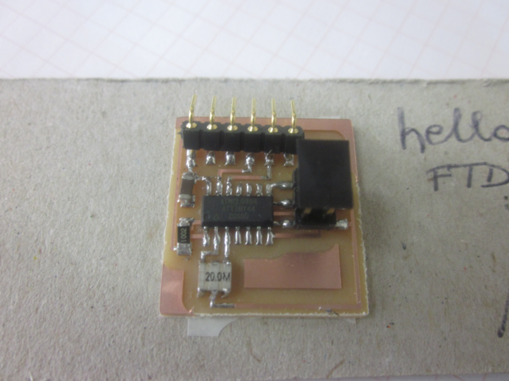 Where is the LED, Amy, the LED?
To top
Reading a data sheet
I always used to laugh with this assignment. Not seeing the point of it. I'm the kind of person that grew up looking at pictures from a manual, never reading what it said and just doing my thing. The only exception to this is working with resin as it has important scale measurement (1/1 or 1/2 or ...). From now on we can add reading a data sheet to info that I do read before use.
Like I said, I ignored this part until pretty far down the FabAcademy. I read the data sheets back in 2013, but as I never really used the electronics, I never saw the importance of it. Until now. A lot of my first boards failed because I didn't read the data sheet or looked at the pins. For me, a pin was a source of power, and that was that. But as I soon found out, it's much much more than just that.
The most important pages for me at the moment are the first ones. The one were the voltage and pin configuration is being explained. By now the configuration of the ATtiny44, ATtiny45 and ATtiny85 is a standard page in my browser and I could as well hang it above my bed.
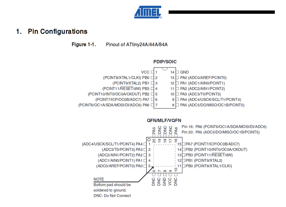 From the ATtiny44A micro controller
With this, there is also an understanding coming within programming of 'high' and 'low', 'in', 'out', 'MISO' and 'MOSI'. Another important page, I would learn later on, is the page where the alternate functions are described. This would become important during the networking and communication week as I'd need those for serial communication.
To top
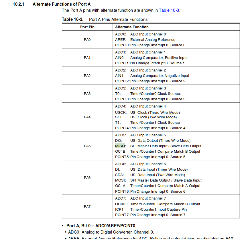 From the ATtiny44A micro controller
LedUp what?
So, as my own hello world board is not going as smooth as planned, we're getting there. I took the board that I'm supposed do adjust for my final project: the Led Up Kidz. And basically, it's a out grown hello world board. It has the same micro controller, several LED's, resistors and other fun stuff. As we teach with this, and I sometimes need to assist, it might be good to understand the full process of what's happening in the Led Up Kidz.
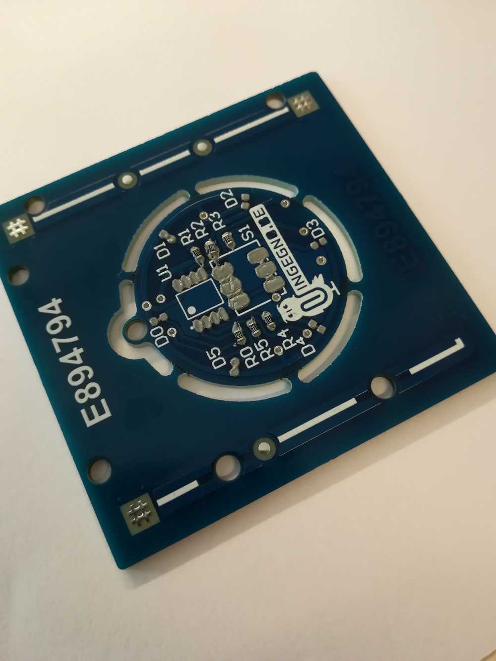 Original Led-Up kidz
To top
Programming the LedUp Kidz
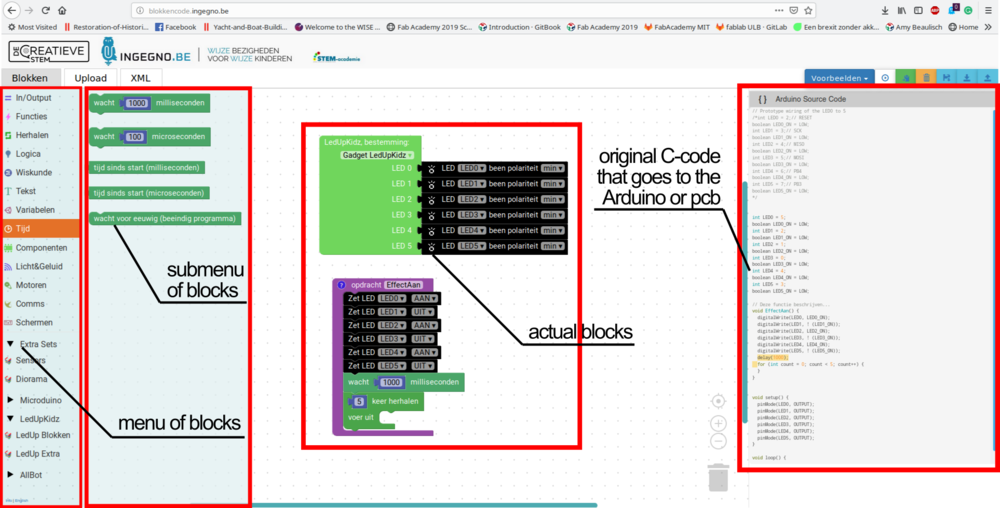
To program my PCB I made use of the blokkencode.ingegno environment, which is based on Blockly. We've adjusted some things to make it more fitting for what we do and teach. And for
kids to understand what they do.
First of all, we have the standard Blockly environment like Blockly itself and more famous: scratch. We, however added an extra part to our screen so that the kids can always see the actual
code being made. We will never push the kids from Blockly into the C code directly and seeing the code change is a easy and fun way to make the step to actual code instead of blocks.
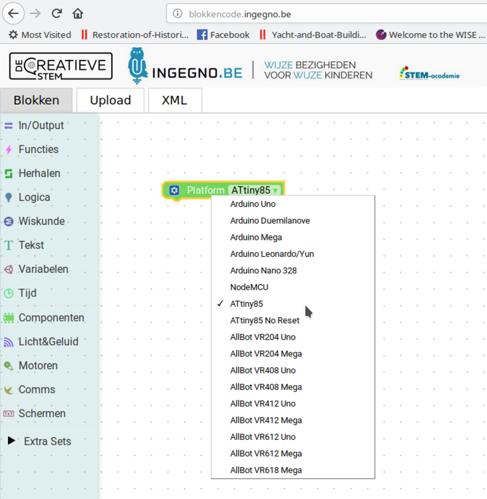
As we never use it to actually program ATTiny's without a bigger project around it, Benny arranged me a ATTiny85 block. It wasn't a big deal to make as our LEDUp Kidz work on the same ATTiny micro controller as that I was going to use.
Time to add the button and more LED's!
The actual code
To make things go smooth I already partly started coding the board for my final project. Below you can find a part of the workflow.
- Define the programmer
- Define the pins
- Let a LED blink
- How does the button work?
As we noticed and will notice over time, there are lots of programmers. I already showed the picture where you can choose what platform you want to use and that we've added the ATTiny85 to it. You need to do this, otherwise it won't work. The architecture inside might be different or the amount of pins. Some important pins to know are the VCC, GND and RESET.
As you know each micro controller has a certain amount of pins. The ATTiny44 has 14 pins, the ATTiny45 has 8 and the ATTiny85 has 8. One of the things that I didn't take into account until much later was that each pin has a meaning (do read a data sheet, or at least google your micro controller!). So I first just randomly wired everything in Eagle, made the PCB and... well, blew up the micro controller. So, you need to define the pins so that the loader and the micro controller will do the right things. You can for example say that pin 1 is a LED, but pin 2 needs to be a push button.
If you have defined the right pin for the LED, you need to tell the pin what kind of information to send (when for example you push a button). This means that a LED can be 'HIGH' (or on) and 'LOW' (or off). You need to define this and let the program know when it needs to change.
The button is often the way to let current pass or not. If we teach kids about buttons, which they design and develop themselves, we explain this to them. It's the last piece of the puzzle that needs to be completed before a circuit works.
Concretely it looks like this:
P1: reset + LED
P2: LED
P3: button
P4: button
P5: battery
P6: empty
P7: empty
P8: empty
To top
Main problems this week
The first problem I had actually dates back from the electronics design week. I couldn't finish my board back then, so combined it with the 'make something big week'. I managed to finish
up my drawing under supervision (I could call for immediate help if needed), and was happy to only have the production left on my to do list (next to soldering but I never really have problem
with that). Once home I etched out the board and ran into 2 problems.
First: the ferric chloride didn't want to etch. It took ages for the etching to finish, and much more than the standard 15 minutes. The problem was that in the beginning I was
eager to see how the etching evolved, and used to take the boards out every once in a while and stir the ferric chloride by doing so. After making some pcb's I got used to the process and didn't
go looking at it as much as I used to do. And this results in my pcb's not etching. It needs to be stirred every once in a while. The solution to it is having a magnet in it that
turns around as you etch, or a vibrating table. I thought about making one myself, but the cheapest one costs around 30 euros. As this won't be my last pcb and we plan on teaching it, it might
be useful to invest in it.
The second problem I ran into was my ISP not working anymore. We checked the error (-71), but the only info we found was dated to 2005. We decided to let it go and simply make new
ISP's once I have the time for it and use the commercial one in our lab for now.
 There is one more thing we will try, and that is to put the ISP in the reflow oven the next time we use it. That way all of the solderings will be re-soldered and we can see if it might have been
a problem there or not.
Once I figured out my etching problem, I cold start soldering my board. Sadly, I only realized then that the xtal that I used in the board is the small one (standard FabLab Inventory) and not the big one that the ULB lab ordered. I did watch the footprints when drawing, but didn't pay attention to that small part. It resulted in another pcb that is useless. As I was quite fed up with everything and always taking 2 steps forward and 3 steps back, I left the hardware for what it was and moved on to the code, planning on redrawing the pcb onca again in the coming week.
To top
Programming the board
After taking out all the child sicknesses from the board, and having an actual PCB it was time to program it. The way we do it at work is to program the controller before we solder it to the board. This sadly also means that it becomes very hard for us to reprogram the whole thing afterwards. See there the big difference between the methods.
Here, at the Ingegno makerspace we have the habit of using a Arduino as ISP. For the time of the course, we made one extra so that I could take it with me where ever I went. The programmer also showed to be more robust then the ISP from the Academy and easier to work with for me.
 Left the programmer that I used, right the one that's made more secure for workshops.
The way of programming might have changed a bit due to this. You don't just use the 'upload' button anymore like we do with any other Arduino, but some special things need to be installed first.
The first thing that you will need is the ATtinyCore. You will need to find it now at the board manager in the Arduino IDE. When you go and change the board now, you see that you have a lot more options than before.
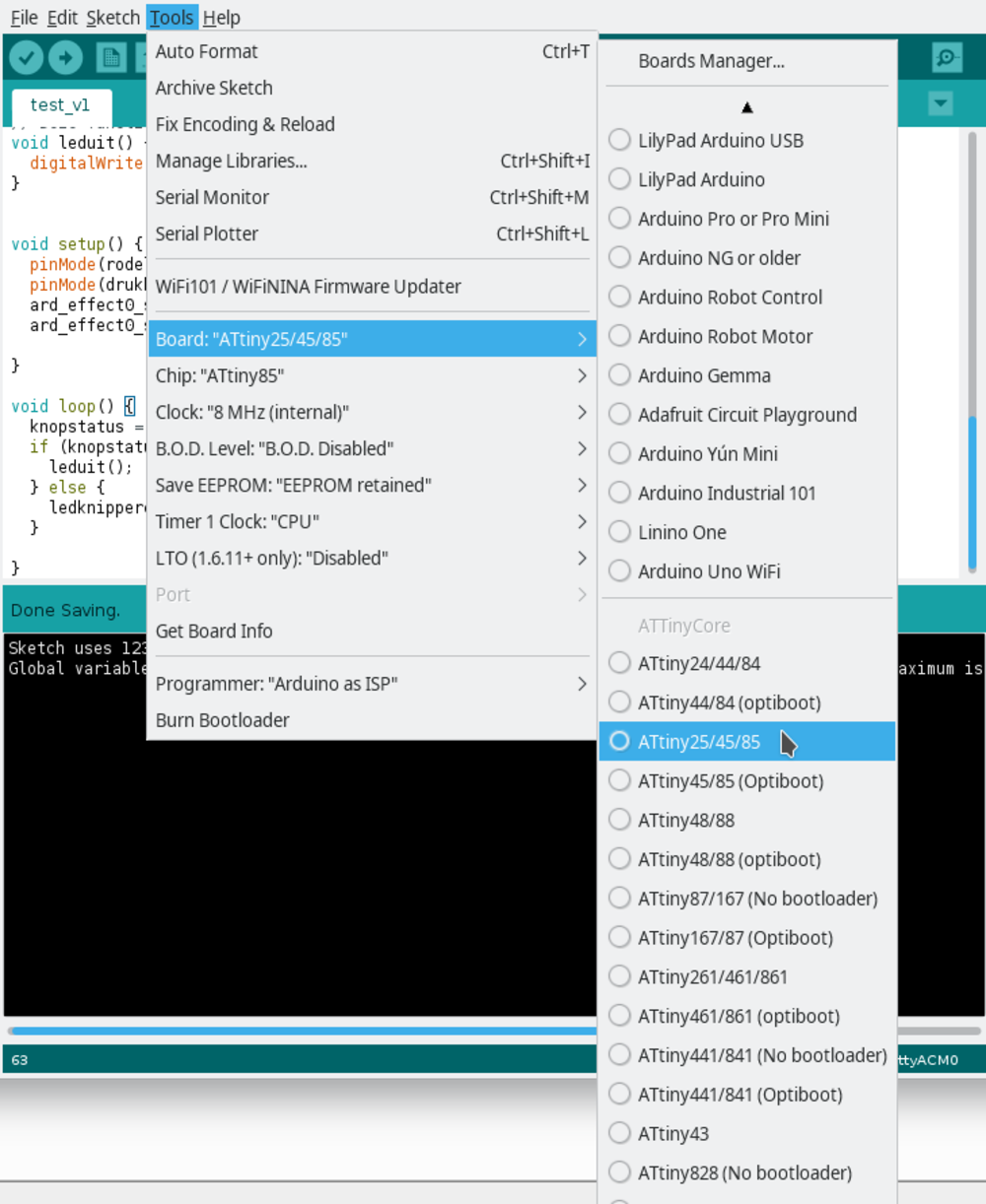 The changement in Arduino to be able to use the Arduino as ISP
You can also see that there are a lot of other settings put in into the Arduino once you change the board to the ISP. Full documentation, in Dutch, can luckely be found here.
Once the set up is done, the programming is pretty easy. You take a micro controller, put it in the holder that's connected on the Arduino, load in the program the same way you are used to do it (via the upload button), and done. The fun part is, that you can add this piece (the jumpy thing) to a breadboard and test out your code breadboraded. To see an example of that, go to the networking week where we first breadboarded the circuit and then designed, milled and soldered the PCB.
Programming steps
- Step 1: Write the code
- Step 2: Place the ATtiny in the holder
- Step 3: Connect the Arduino as ISP to the computer
- Step 4: Upload the code to the ATtiny.
- Step 5: Solder the ATtiny to your board.
I wrote the code in Blockly, and copy pasted it in Arduino.
 ATtiny in the holder
You can use the normal way of programming the ATtiny as with a regular Arduino if you click on the 'upload' button in the Arduino IDE.
To top
The code
As I got delayed with the hello_world board, I used this week to program the board from the past assignment. All documentation can also be found there. But I'll take this assignment to go into more detail about the code from the hello_world week and the embedded week.
In the picture below you can see that the code in Blockly is build up in different colors. The first color is green.
In the green part, you are defining the board in which you are programming. In my case it will always be a ATtiny85 as this is the chip with 8 pins but the biggest memory. Before the Academy we didn't have the block like this. We had it, but it was already integrated into another project. So I asked Benny, the IT coordinator here, to make me a special, pure ATTiny block.
The second part is the the function within my code. It tells you what you want it to do. In my case we want the LED to blink. Afer that come more functions in wich you specify the assignments that you gave in the upper part.
At last, you define everything that has to do with the button.
 The code in Blockly
To top
Reflection on this week
This week I really learned about project planning and more especially priorities. I left the board for what it was and focused on the code and my other work that I have to do. Most things on which I was stuck, are, or not my fault (the ISP breaking) but just a lack of time. I'd need a full day or 2 to finish up all the assignments, fix the rough edges of my documentation and be up to date again.
To top
Manuals and files