Group Assignment is well described in my classmate Tue's documentation.
Vinyl Cutting
For the vinyl cutting assignment I chose to make it a useful project for my master thesis project. In my masters project I am holding a workshop with an organization located in Barcelona where the volunteers are migrants or refugees. The purpose of the workshop is to create personalized stamps and stencils for each participant and to illustrate how the work will be done I decided to make stickers with the logo of the organization so as to give them out.
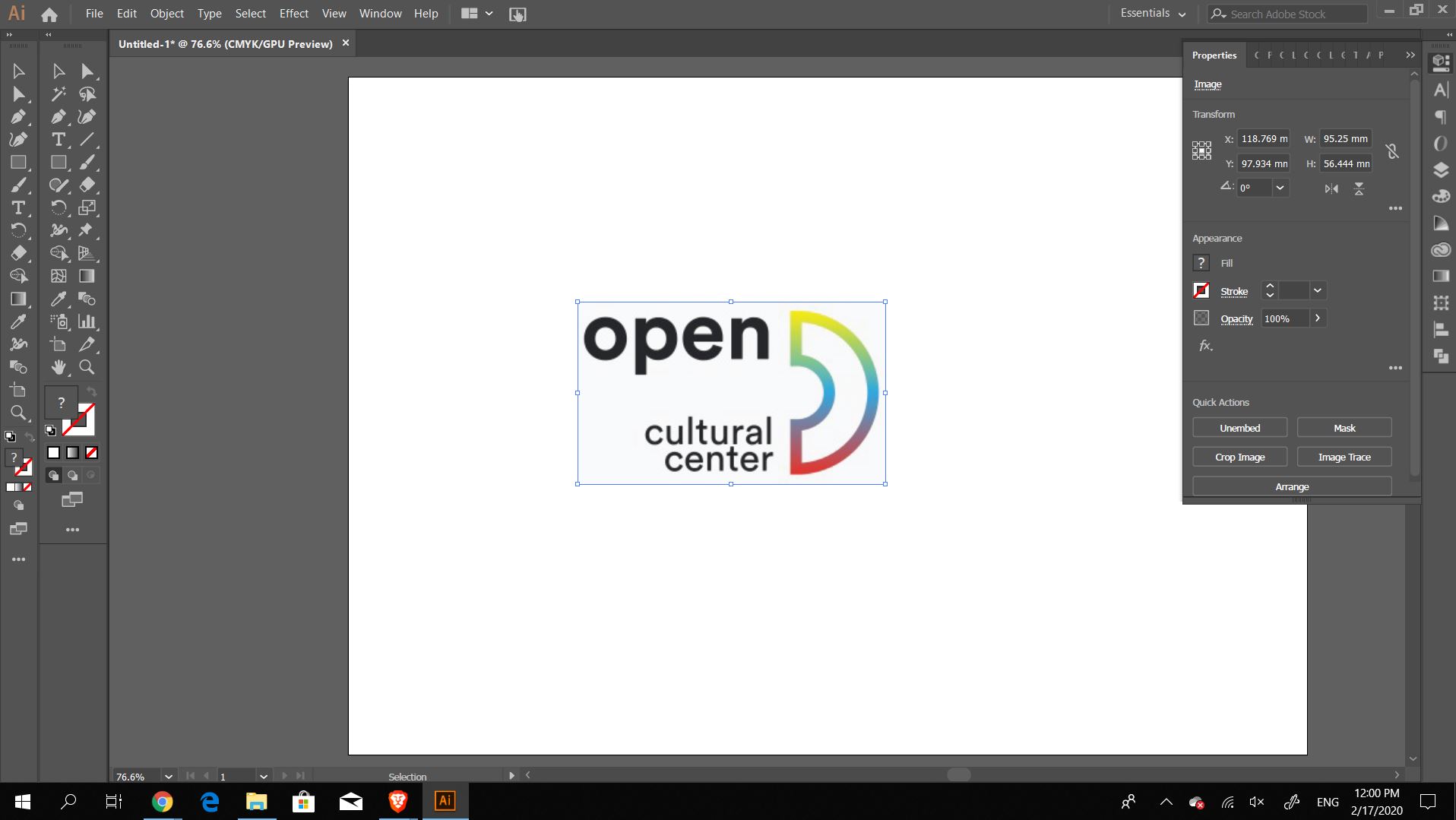
As I am most comfortable in Adobe Illustrator, I decided to vectorize the logo there before moving on to the vinyl cutter software. In Illustrator I began by embedding the image and then tracing it, I traced it using the defaults so I do not lose any features. After I was satisfied with the shapes, I expanded it, removed all the fill colors and added strokes as the outlines. Once that part was done I exported the file and opened it with Silhouette Studio which is the software that comes with the vinyl cutter. First glance, the software is a little similar to inkscape (which means its simplicity makes it confusing to me).
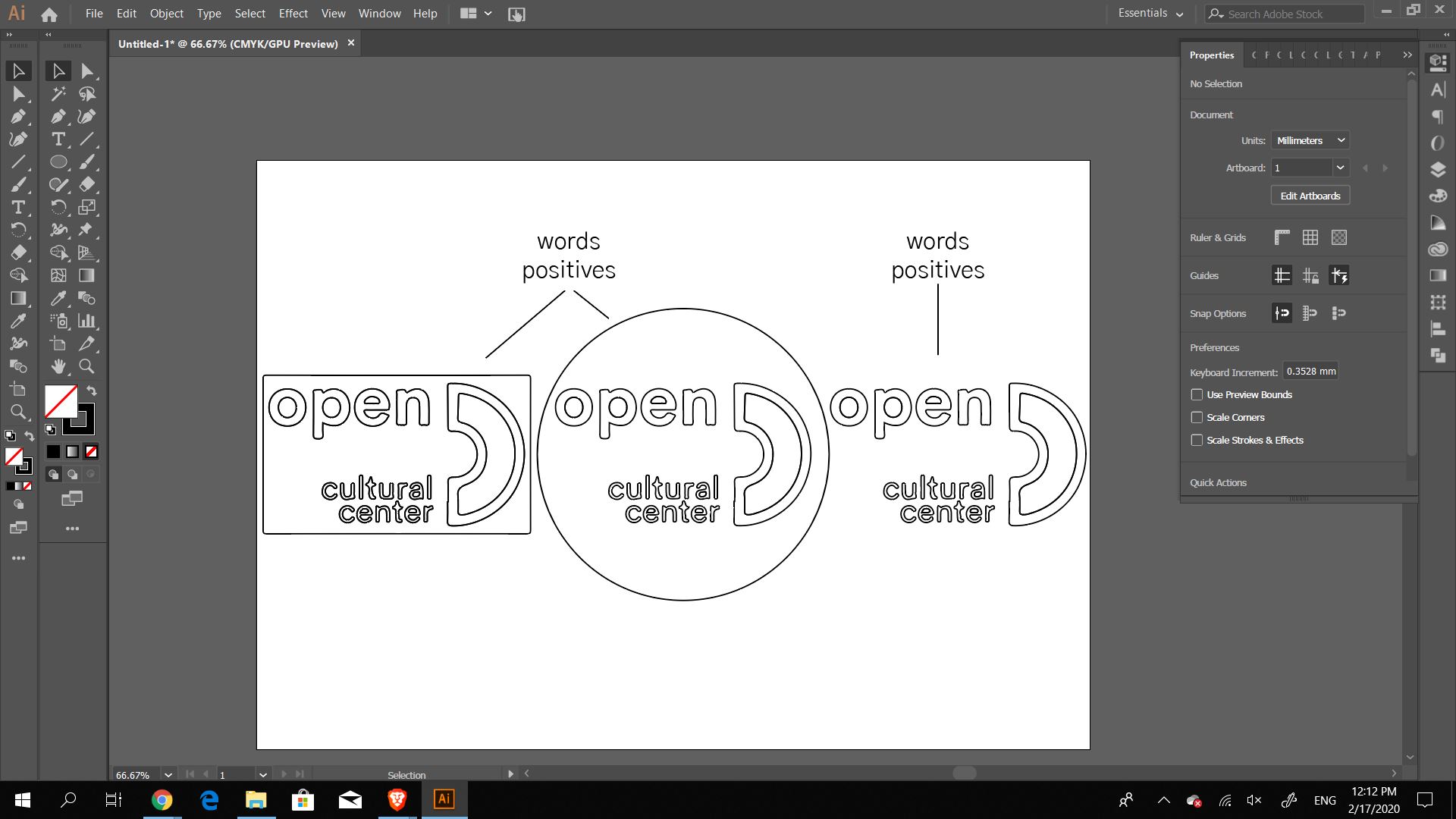
In the design aspect of the stickers I wanted to also test whether I needed the positives, the outlines, or the negatives, the white spaces. This part will come later on when the weeding turn comes up. I have previous experience with vinyl cutting by making vinyl for the Fabrication Lab in my school, and so I knew that the lettering will need to be changed to make sure the letters stay connected to each other; however, as this was a testing stage I decided to not mess around with them just yet. Since the software part was already set it was time to focus on the steps of setting up the vinyl cutter.
Vinyl Cutter
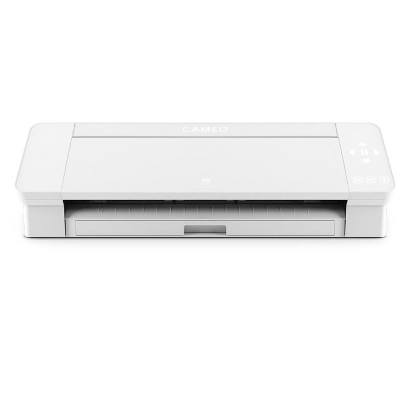
The machine I am using is the Silhouette Cameo.
The Cameo 4 is a 12-inch width desktop cutting machine that lets you make precision cuts in vinyl, cardstock, fabric, and more.
Some of the listed features include:
- True 12-inch cutting width (when using a cutting mat)
- Matless cutting capabilities
- Cut up to 10 feet length materials
- Dual motor system
- Most powerful force in machine class (5,000 grams force)
- Fastest cutting speed in machine class (up to 30 cm/second)
- 3 mm clearance for thicker materials.
- Built-in roll feeder allows you to easily load and cut rolled materials like vinyl and heat transfer.
- Autoblade for pressure and blade length
An easy to read step-by-step explanatory tutorial is made by The Pinning Mama where she explains the definitions and steps of useing this vinyl cutter.
The first step was to check the pressure and lenth of the knife, as the vinyl cutter was in use before my appointment these measurements were already set. I double checked the length of the knife by placing the tool flat on the vinyl and made a cut by hand, it cut the vinyl without going through the backing which is the perfect length. The Autoblade was placed on a level 1, the speed at 5, pressure at 10, and passes at 1
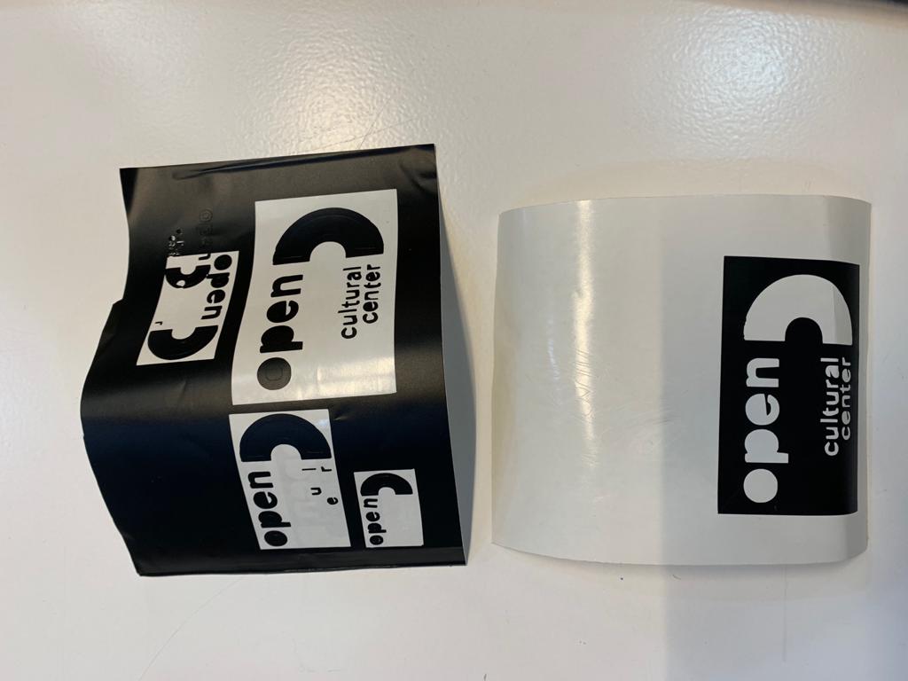
Through my first test I have noticed that the corners of the letter were not cutting well and clean. The reason for that could be because of the small size of the text I have used or another could be because the pressure being applied is not enough. For that reason I increased the Autoblade setting to 2 and kept the other settings.
Final thoughts
For this stage was that it was a failure. I did not find the best settings needed to cut at the size that I wanted the stickers to be and I could not find the best pressure to make sure the corners cut well. Which then made the weeding process difficult where some of the tiny letters are gone or the inner parts of the letters do not even cut.
Grasshopper Design
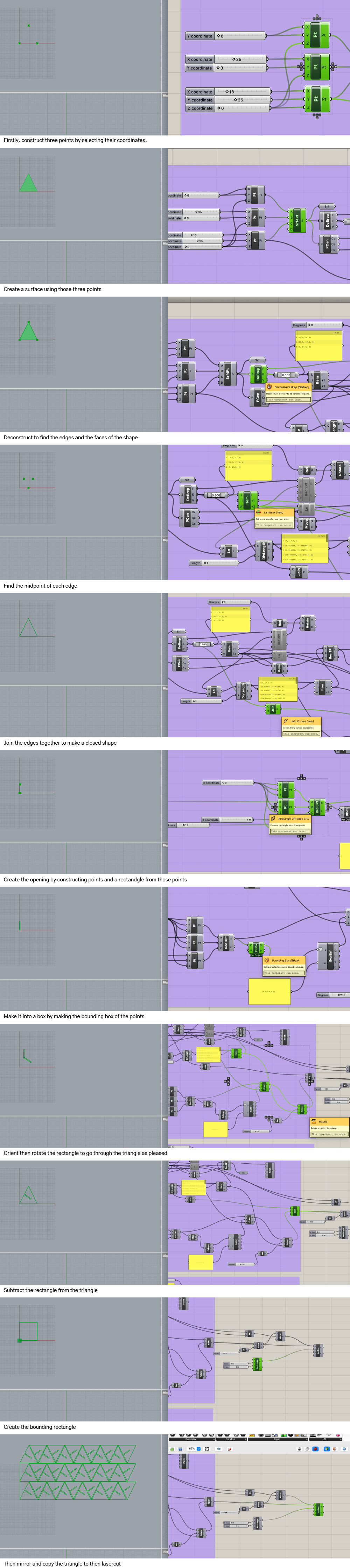
To laser cut a press-fit parametric construction kit I wanted to focus my energy on learning how to design the simplest joint in grasshopper more than the focus on how to use the laser cutters. The laser cutters are an easy tool that I have used successfully extensively and wanted to focus on how to create a parametric design on grasshopper from scratch. My first idea was to use the folding methods on thick paper, by lightly cutting lines on the paper along with joints and then folding them and connecting the with each other. I began to use grasshopper and realized that, since it was my first time really using grasshopper, it is best to focus on a simpler shape and understand the logic behind designing it and then later on focusing on the tolerances. I decided to design a triangle from three points with an angled slit where I could play around with the shape of the triangles and the size of the opening according to the material used.

As I began to work on the triangles, I started with three points that had different XY coordinates. While asking for support from a few more experienced grasshopper users, I was told that the method that I chose to design with was not the easiest way to design the triangle and that using the polygon tool might have been easier to start off with. My reasoning was to be able to play around with the coordinates to create different shapes in the easiest way for quick prototyping on the lasercutter.
After the points, I created a surface from those points.
To be able to find the midpoints of each edge, I deconstructed the surface to find the three edges which I then divided by 2 to find the midpoint.
Afer finding the midpoint I divided one segment of the edges to increments that I could control, starting with 1mm.
Once the triangles were set, I moved to creating the rectangles that could be aigned directly to the edge I divided.
The rectangle was created by defining three points to be able to change the thickness of the slit/hole depending on the material.
After the points, I created a 3point rectangle and then a bounding box for the rectangle that was deconstructed, reevaluated, and then oriented to match the midpoint of the triangles.
Once the two shapes fit well together I used the region different component and then arrayed them to fit into the size of my material.
Laser Cutting
Group Assignment
There are two groups within my lab that made the tests for the lasercutter'spower, speed, frequency, and Kerf. The group assignment is very well described in my classmate's documentation Tue Ngo and Antoine Jaunard. One thing that I will remember every time I use the machine after the tests is that the Caliper is our best friend and I had not understood precisely how to use it beforehand.
Individual Assignment
I used the Trotec Speedy 100 for this assignment as it was the one with the tested settings. The machine has a bed size of 600x300 mm and a alser power of 12-60W.
To find the settings needed for my material, I looked at the suggested settings by the lab and made a test cut and then adjusted accordingly, as outlined below.
I decided to use task board or illustration board for my designs. I used a caliper to measure the thickness of the material, 2mm, and started with a test piece. I defined the dimensions on Rhino and sent it to print through the Trotec driver for the machine.
When clicking on print the first step is to set up the size and type of the material. My materil is task board and the size was the size of the cutting board.
The cut lines are drawn in red and so in the driver there is the options to change the power, speed, and frequency of the laser.
I started using the power of 50, velocity of 4, and frequency at 1000. I began with those options as the material I was using is composed of paper it does not need very high power to cut but it does need the speed to be a little high so it does not linger on one spot and burn.
The first try did not succeed with these settings, it did not cut all the way through the material.
While testing the first cuts, I cut it and then used the caliper to measure the difference between the dimensions on Rhino and the dimensions in real life. There was 0.2mm difference, Kerf.
I then offset my shapes by the 0.2 mark and tested two pieces to check if they fit in together well. Unfortunately, the sizes did not work, I needed to change the thickness of the hole again.
I rechecked the focus because I felt the line was a little thick; I used the manual focusing tool and moved the bed up a little more. That fixed the thickness of the cutting line but it did not fix the cutting through.
To fix that I first incresed the power to 70 and tried again, it cut much better but still not all the way through.
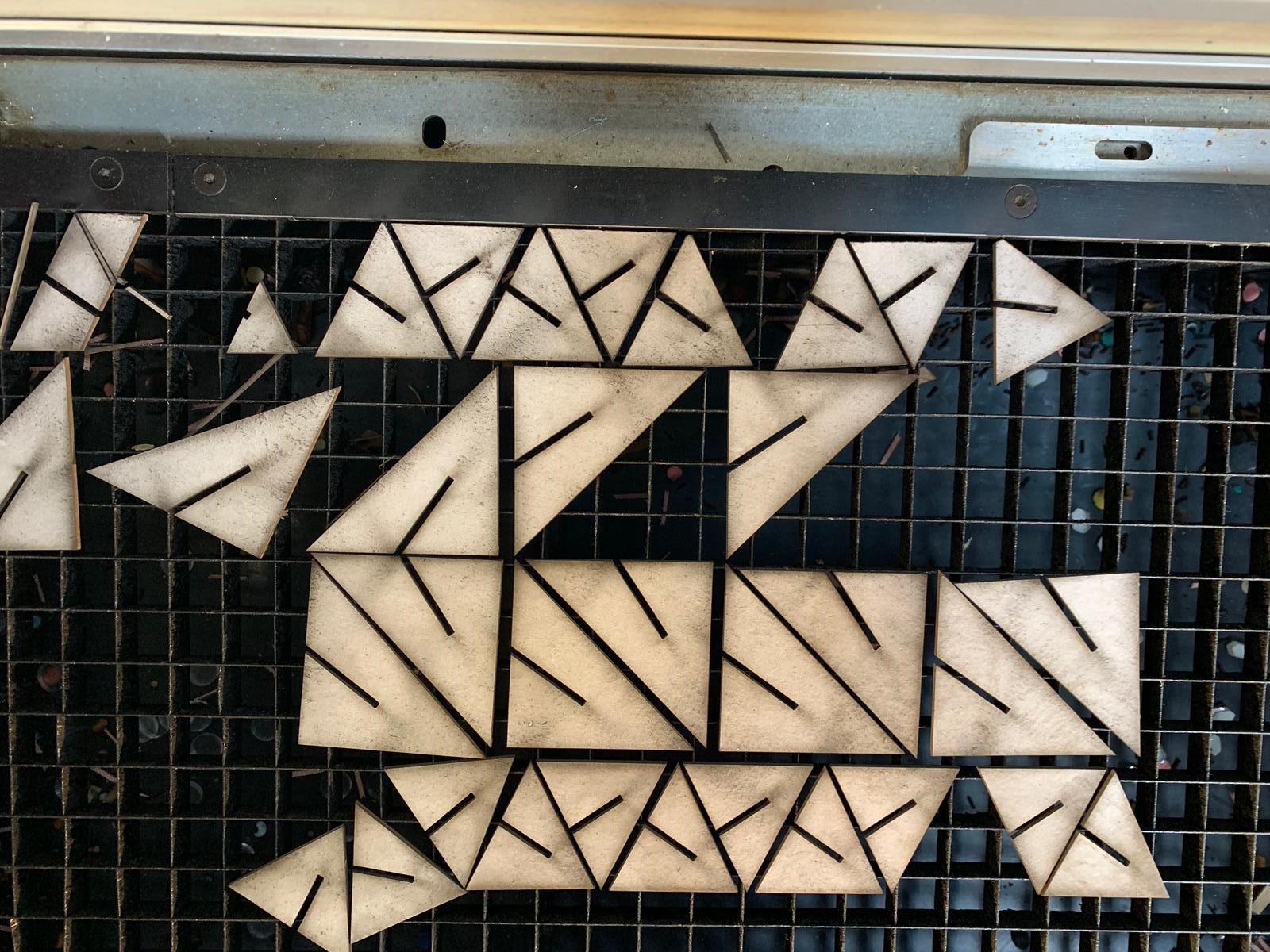
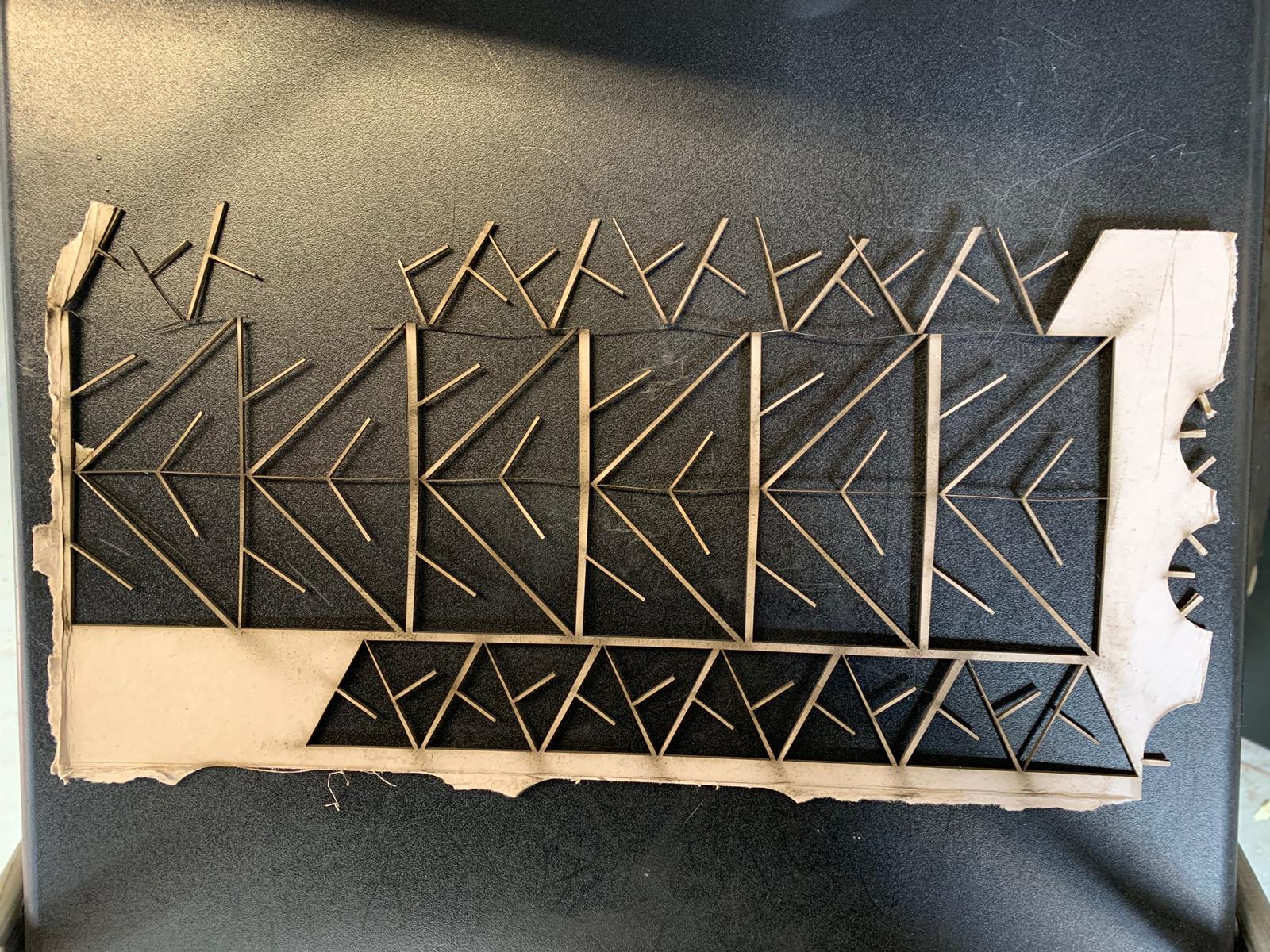
The final settings that cut perfectly were: power 85, velocity 3, and frequency 1000. The frequency was not adjusted as I wanted a continuous line to keep cutting.
The size fit together better when I decresed the thickness of the slit and took into account the Kerf measurement.
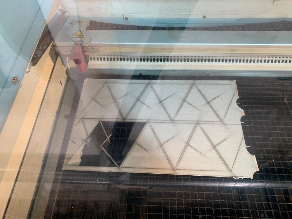
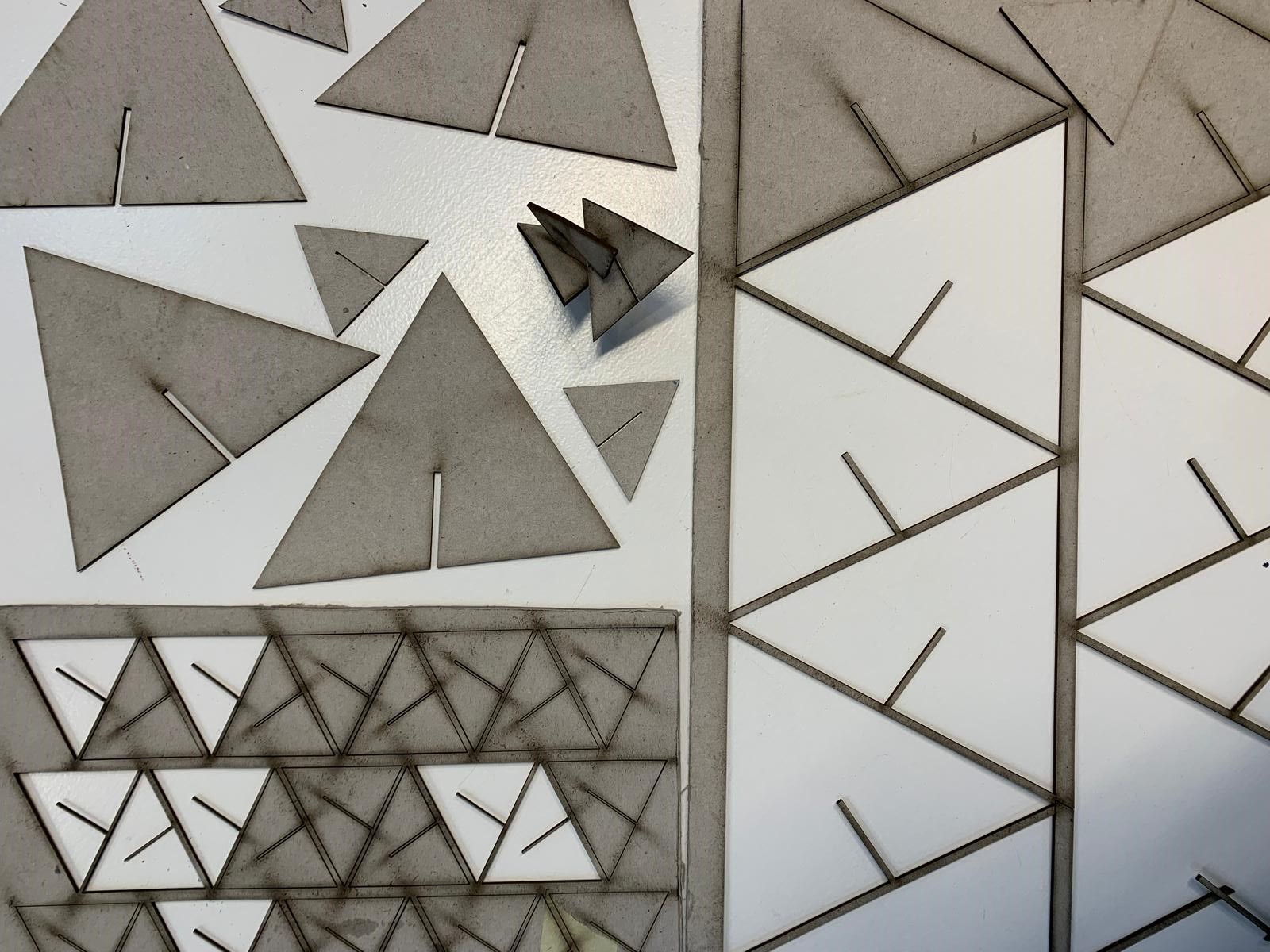
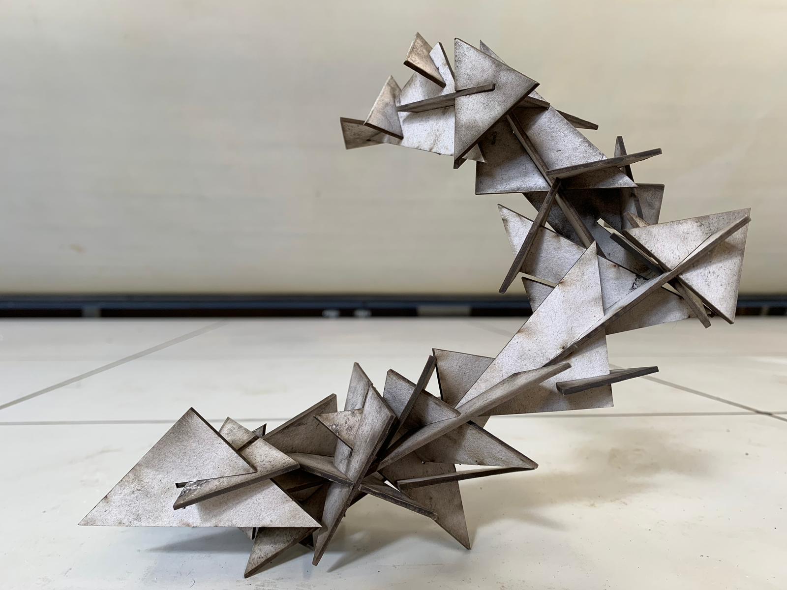
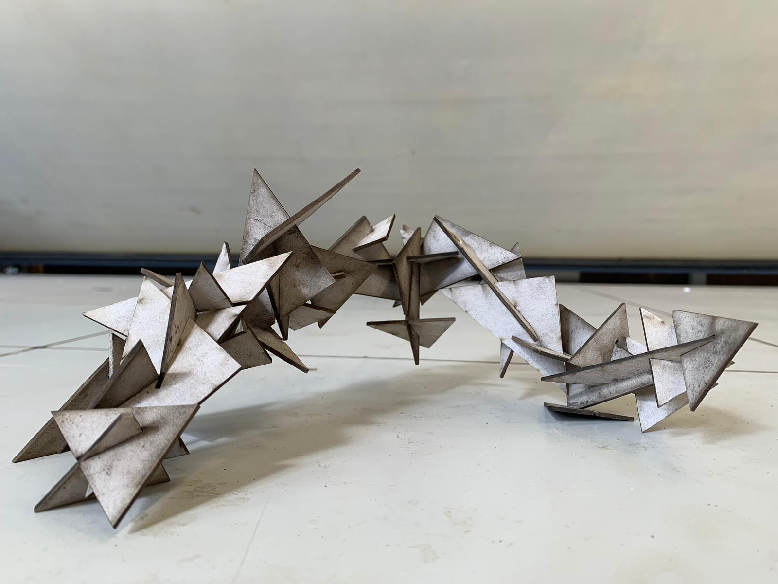
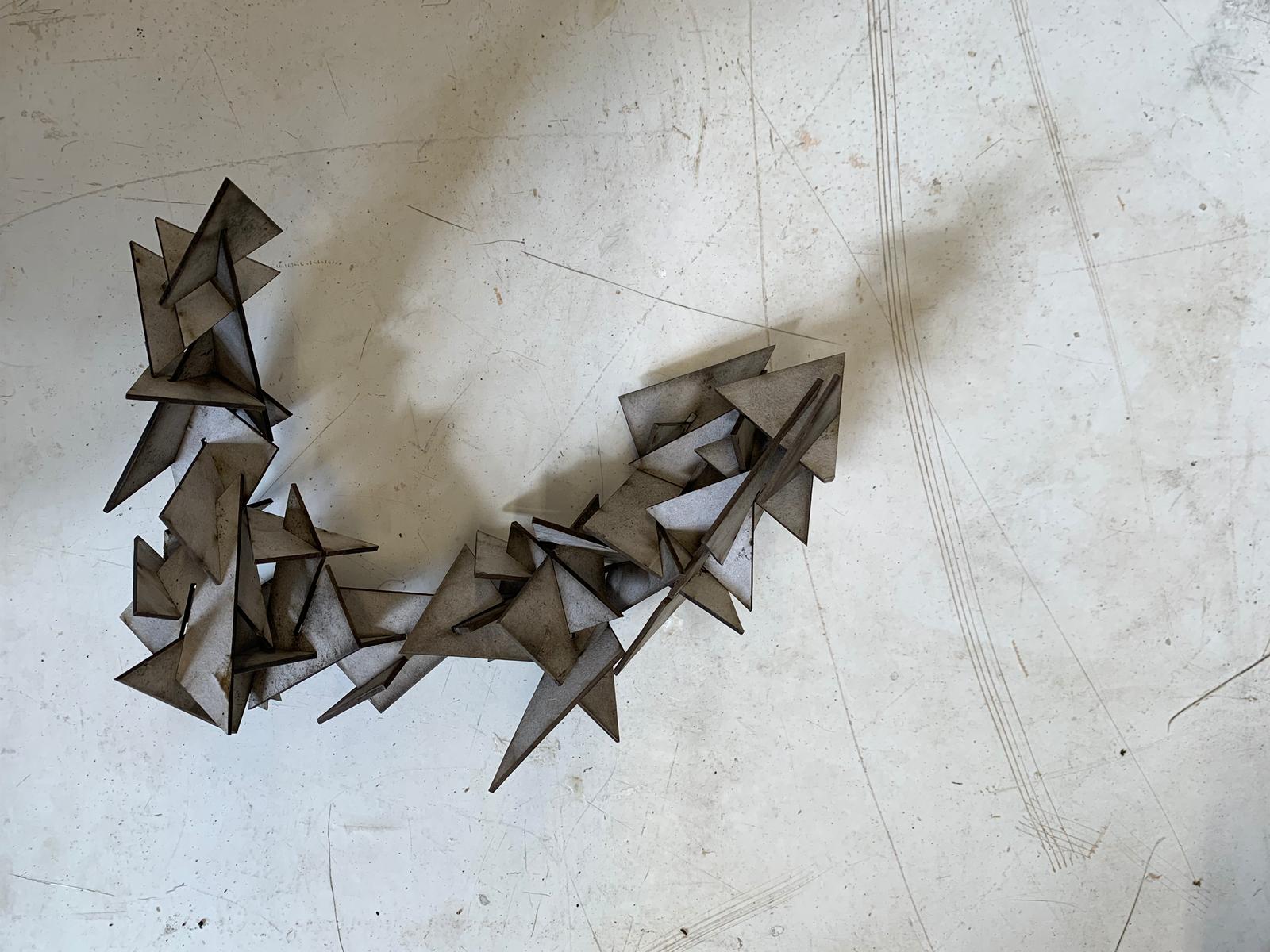
Once I made sure the settings were at their best, I decided to cut two different triangle shapes, sizes, and slit angles. It would make the overall design much more interesting. I cut a new piece of my material and I realized that there was a variation in the thickness. Now the thickness of the material was about 1.7. I altered the sizes of the joints and tested the cut. At first they were too small and I readjusted them to be at 1.5 (taking into consideration the 0.2mm kerf measurement). The 1.5mm joint openings fit really well and I cut the material. While assembling the construction kit I found that some joints fit better than others, proving that the material had even more variations.
Final Thoughts
Through the testing and cutting of this week I decided that I would like to test out the press-fit idea on a larger scale through the Computer Controlled Machining week in a piece of furniture that is modular. I would like to create a modular and functional piece of furniture that would not need any glue or screws. As for the laser cutter findigs, I have never really focused on the importance of designing with the Kerf and would usually test a million times before finding a size that fits; however, with having the Kerf outlined for the machine and the materials used it requires less tests and saves a lot more material. Another important point is to always double check the focus, if you think you have focused the machine focus it again.
Files