This week's assignment is to characterize a laser-cutter (in-group); to cut something with the vinyl-cutter (individual); to design and to laser-cut a parametric construction kit (individual).
* All DXF and original editable files can be downloaded here.
* This week's group assignment is to test the proper power, speed, frequency and kerf values of different materials using a laser-cutter. In order to explore possible materials for my Final Project, I also conducted a personal joint clearance and kerf bending test with living hinges.
* Besides, we are required to individually design and cut something with the vinyl-cutter and to laser-cut a parametric construction kit that can be assembled in multiple ways.
Vinyl cutting
Individual assignment - Cut a vinyl sticker
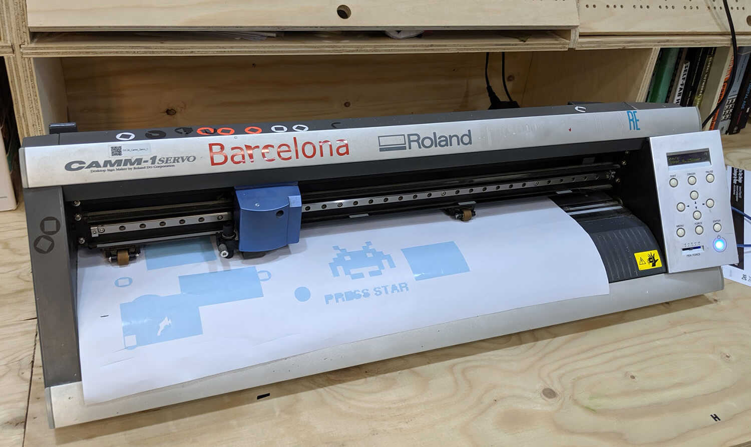
I used the Roland CAMM-1 Servo GX-24 to cut a sticker of the logo which was designed in the previous assignment. The detailed specs of the machine:
- Work area: 584 x 24,998mm
- Cutting speed: up to 500mm/s
- Cutting length: maximum 25m
- Cutting width: 50-700mm
- Cutting force: 30-250gf
Some essential steps to use the vinyl-cutter:
- Export the
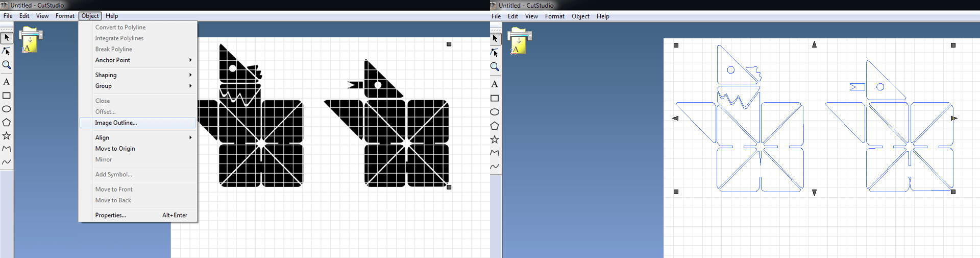
.aifile to a.epstemplate or a.bmp/.jpegimage. I exported my file to.bmp. - Import the
.bmpfile to CutStudio, choose Object > Image Outline to get the trace of the design - Load and fix the position of the vinyl paper, then adjust the blade. We need to make sure the vinyl paper will not be cut through, but the desired parts will be able to be peeled out.
- Move the blade and set the origin wherever I want the cut to start, and choose the setting Roll
- Press Ctrl + P and start cutting!
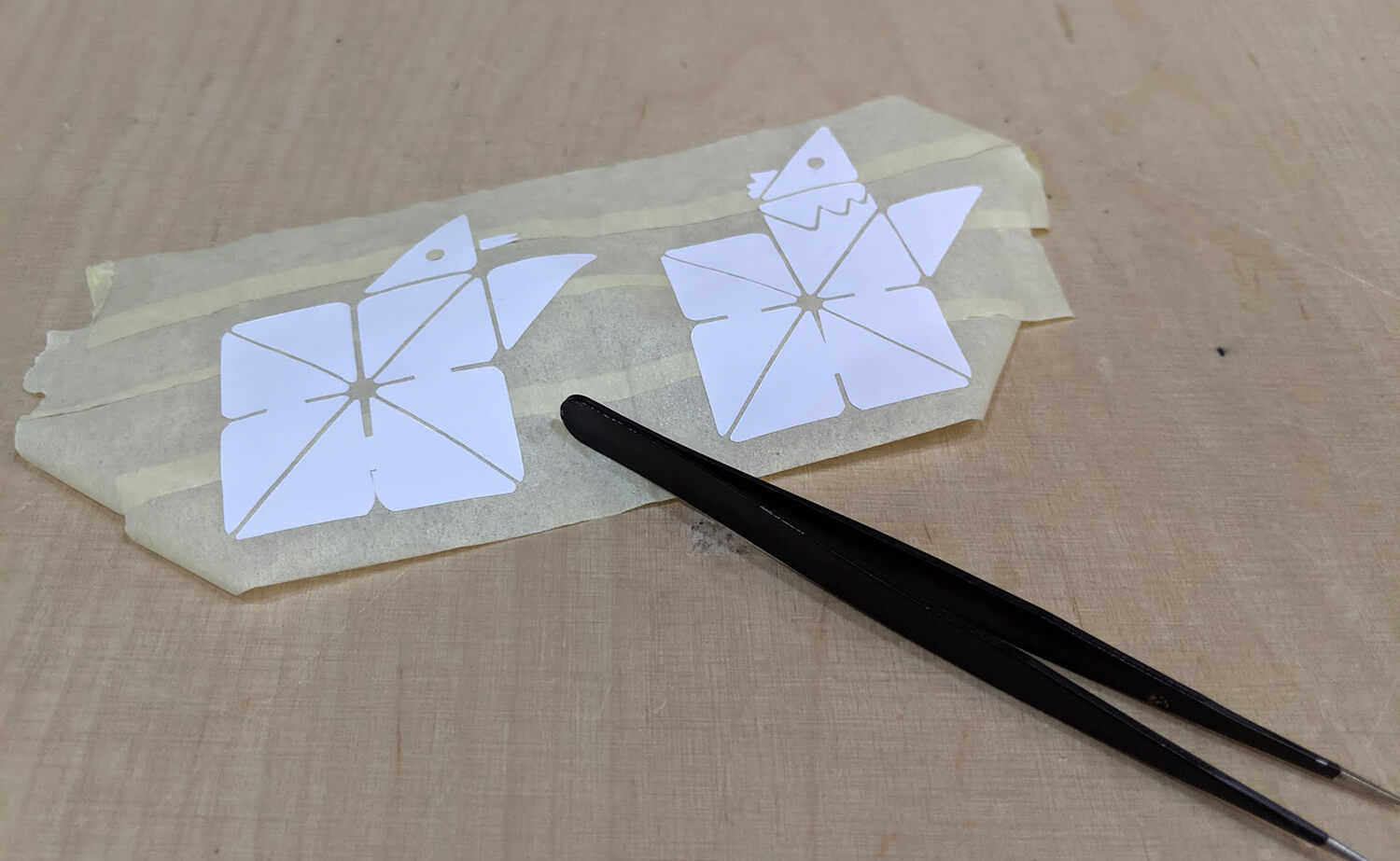
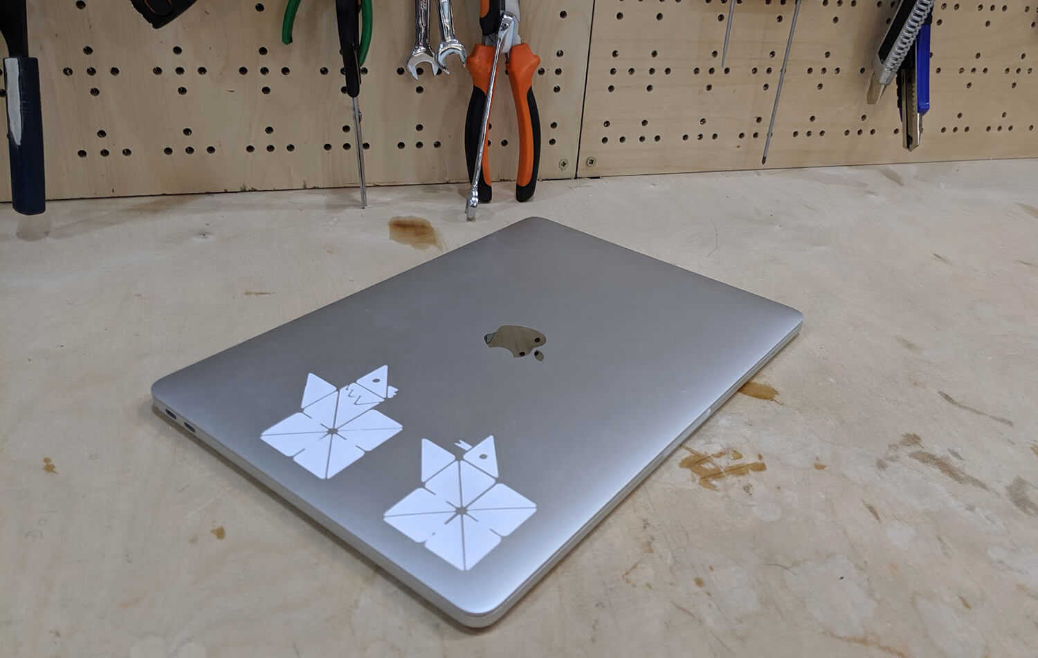
After having my logo cut, I used masking tape to get the parts I want out and put it on my laptop.
The final result looks super nice though!
Laser cutting
Group assignment - Characterize the laser-cutting process
Our class decided to split the group based on who could come to the lab on Friday or Monday. For the Friday group, we tried to cut many pieces of different materials so each of us could go through the process once. I've worked with these classmates during my session: Arman Naraji, David Prieto, Antoine Jaunard, and Benjamin Scott.
First test - Cardboard 4mm
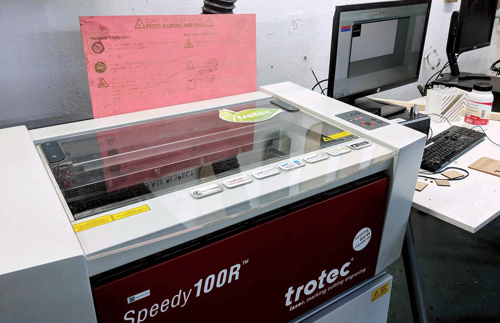
We used this test file provided by the instructors to test the laser cutter Trotec Speedy 100 with different materials. The detailed specs of the machine:
- Work area: 610 x 305mm
- Height: 132mm
- Laser power: 12-60W
We chose to proceed with cardboard 4mm and plywood 4mm because we could find nice leftovers of those materials. I've personally learned from Santi that flexible plywood is not a good material for cutting.
The controller of TROTEC laser-cutters, TROTEC JobControl, calls the processes slightly different from us: the raster engraving process is called Engrave, the vector engraving process is the Cut one with way faster speed, and the vector cutting process is still called Cut. For the Material Settings in JobControl, we followed the information on the samples at the Fab Lab. The parts to be raster-engraved were color-coded with black, and the parts to be vector-cut were color-coded with red.
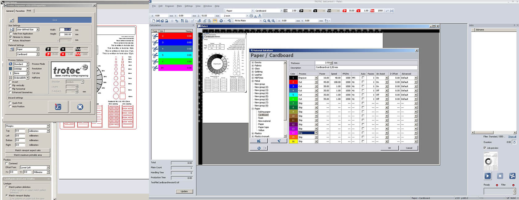
The settings we used for cardboard 4mm:
- Engrave (Raster): speed=100, power=60, PPI/Hz=1000
- Cut: speed=1, power=40, PPI/Hz=1000
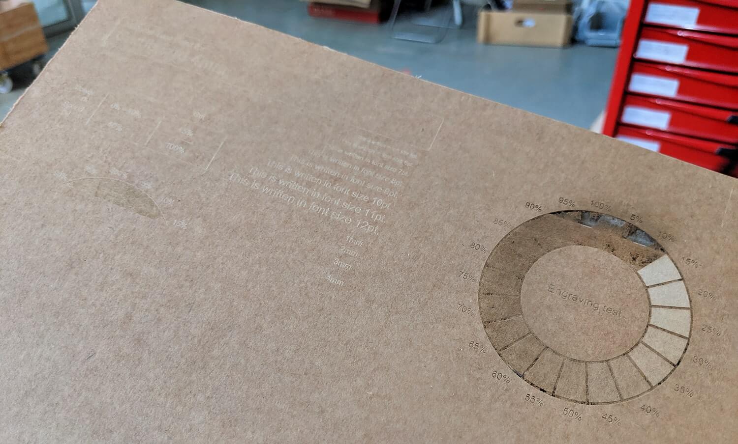
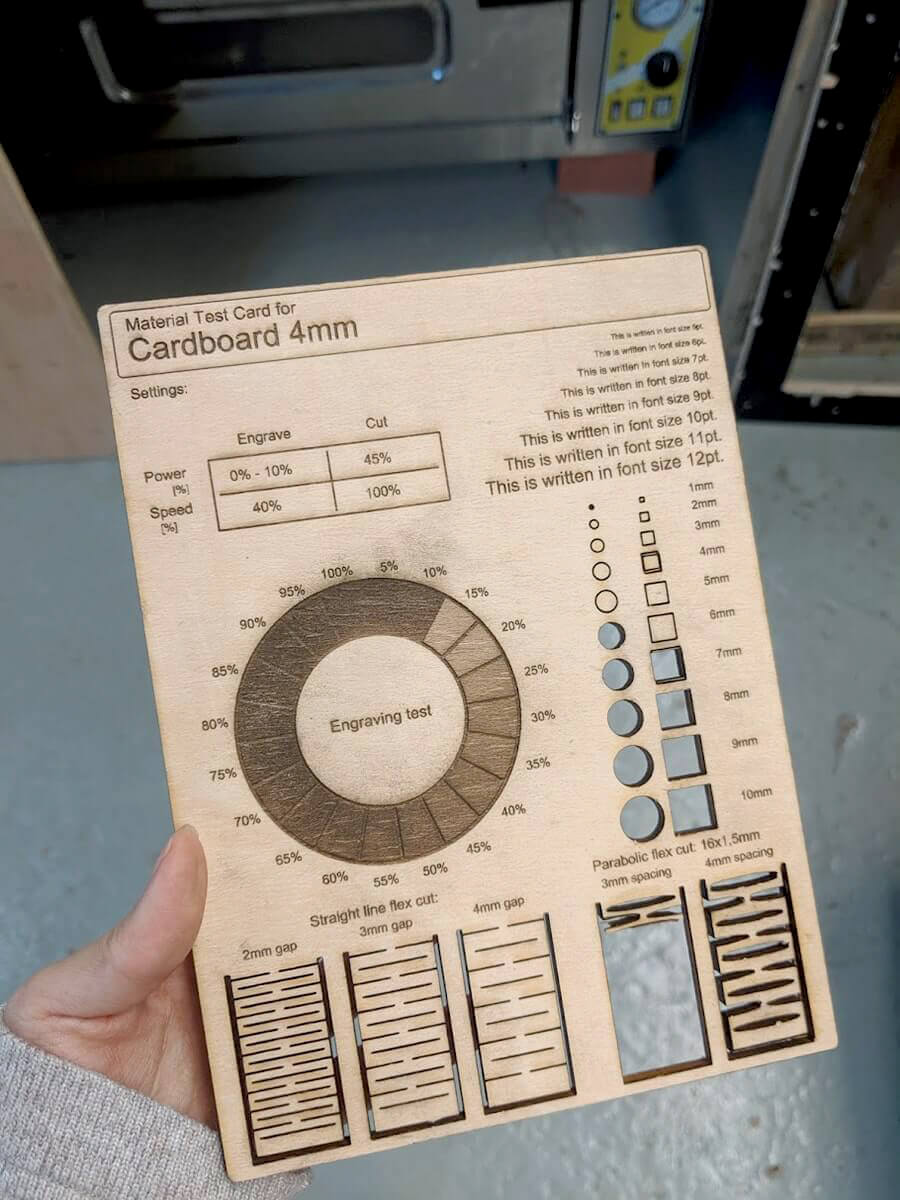
Below is the result of the first test. The power seemed to be over-increased, hence the cardboard was burned while being raster-engraved:
Second test - Plywood 4mm
This time we divided the parts to be raster-engraved and the parts to be vector-cut into 2 separate layers, export them to JobControl with different outputs (raster and vector) and cut them in 2 separate cuts. The settings we used for plywood 4mm:
- Engrave (Raster): speed=100, power=80, PPI/Hz=1000
- Cut: speed=1, power=75, PPI/Hz=1000
The process was totally enjoyable:
However, the plywood was not cut through, and we had to both reduce the speed and increase the power: speed=0.8, power=80, PPI/Hz=1000. We executed the job once again, so the cut was a bit messy. The outcome is not perfect, but it's fine.
The result of the second test:
What I personally learned
Translational speed, laser power, and cutting kerf:
- Cutting kerf width is the width of material that is removed by the laser beam during a cutting process. Kerf width depends on many parameters, such as the thickness of the material (the thicker the material, the bigger the kerf), type of material (for example, I assumed that acrylic with low melting point will tend to create bigger kerf than plywood), the machine itself, the focus of the beam, and the settings of power, speed, and frequency.
- The delicate balance between translational speed and laser power defines the quality of the cut as well as the kerf width. We should abuse neither power nor speed.
- As power increases, the energy in the laser increases, which will result in a deeper cut and a bigger kerf. High power could also make more smoke and charred edges. So, power is a necessity to reach a required cutting or engraving depth, but over-using it is quite destructive to our materials.
- As speed increases, the energy is exposed to a point in a shorter time, which will result in a shallower, more unstable cut and a thinner kerf. Increasing speed will also quicken the cutting time.
Tips to laser-cut like a boss:
- Safety first: the laser-cutters cannot be left unattended, and the air ventilation should always be switched on.
- We need to test the proper settings for the chosen material and machine: power, speed, resolution (for raster engraving) and frequency (for vector cutting)
- We need to measure the kerf width and modify your design accordingly (measuring with the caliper is quite handy)
- We need to nest the design within the cutting area, remove hidden lines completely, ensure 1:1 scale, and color-code them respectively to the execution order: raster (engrave) > engrave (vector cut with faster speed)> inside cut (details) > outside cut (borders)
Individual assignment - Parametric construction kit
The very first thing I learned this week was time management. Staying in the queue for using the machines can be a disappointing waste of time if we don't know what to prepare and how to organize what to do. At the end of the week, I could only proceed with a press-fit design that meets the minimum requirements of the assignment, and I was still left with the desire to try out more design techniques (waffle, bending or stacking).
Designing with OpenSCAD
I find that pre-calculating the possibilities with which the pieces will be assembled will inadvertently limit those possibilities to what I can imagine, thereby reducing both the flexibility of the design and the creativity of ones who will actually use it. Therefore, instead of following the usual "unfolding" process, I switched my approach to simply defining a certain rule for the pieces of the construction kit.
The most important requirement for this week's assignment is that our design must be parametric. Parametric design is basically designing based on defined parameters, and by changing those parameters we can quickly adjust our design. After consulting some images online with the keyword "cardboard parametric design" as well as observing some of the previous year's models available at the Fab Lab, I decided to create a series of isosceles polygons, starting from triangles, squares, pentagons, and ending with hexagons. There would be different sizes for these polygons as well. After cutting and testing, I would add other supporting pieces, if necessary. With this in mind, it was obvious to know that OpenSCAD is the ideal choice to implement the design. Its object-oriented modeling capabilities would greatly reduce my time drawing the pieces.
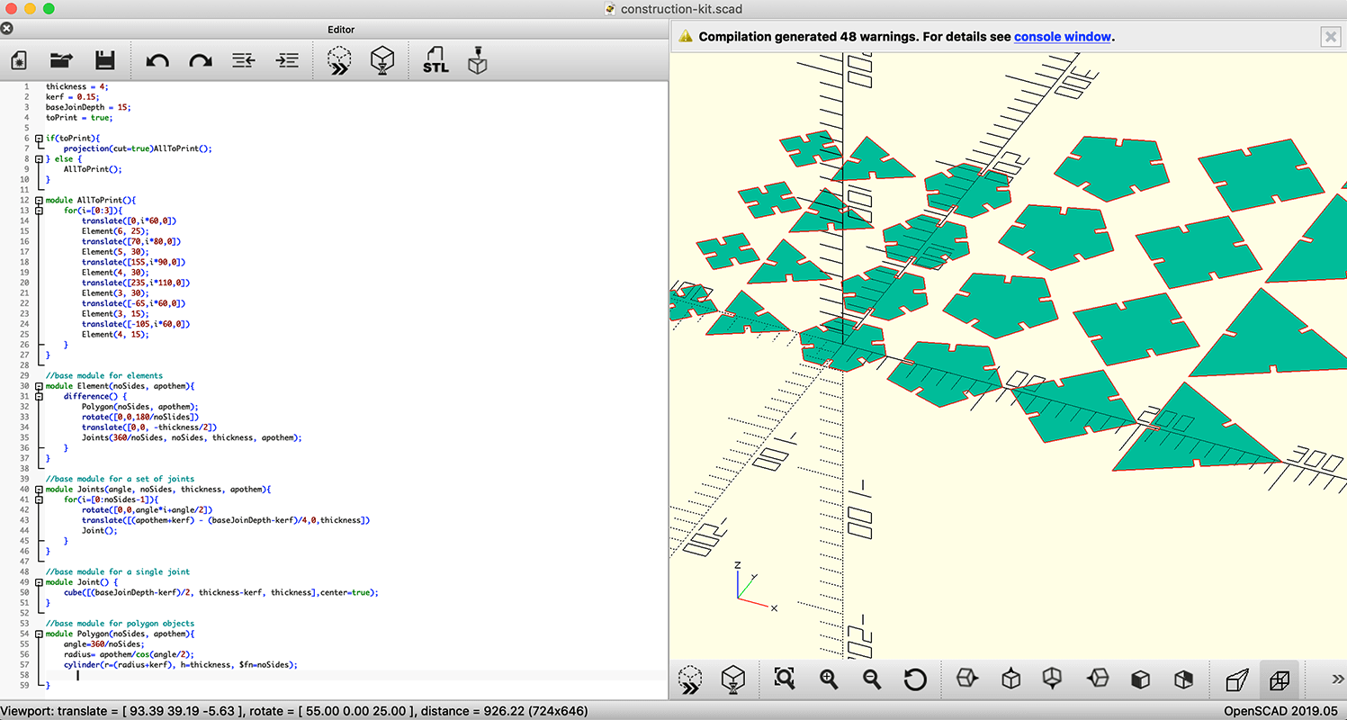
Here you go the detailed steps:
- Some "global" parameters of the design: the thickness of the material, the depth of the joints, and the cutting kerf width
- Define a base module for a
Polygon()with 3 parameters: the number of sides, apothem (inradius), and material thickness - Define an
Element()module from aPolygon()and its related set ofJoints() - Call
Element(), duplicate pieces and place them all together - Use
projection(cut=true)to flatten the set of pieces - Render and export to
.dxf
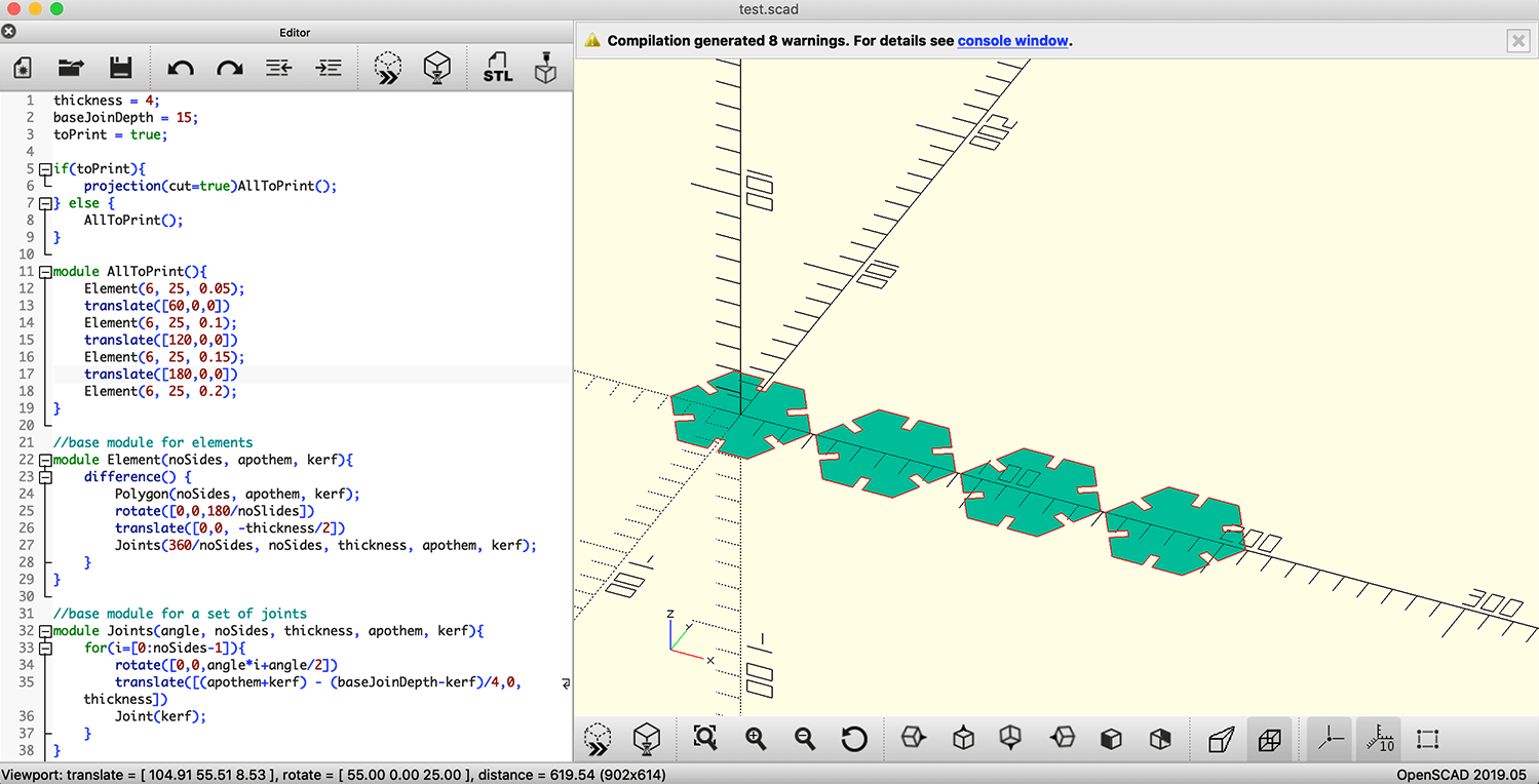
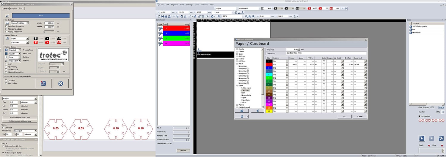
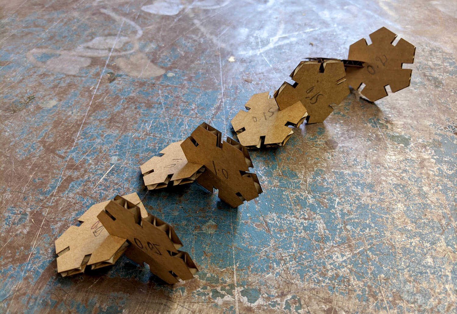
In order to test the kerf width and joint clearance, I directly used the hexagon pieces in my design and proceeded with these following values of kerf width: 0.05mm, 0.1mm, 0.15mm, 0.2mm. NOTE: kerf width=0.15mm means to allow an offset of 0.075mm from each side to make a perfect fit.
Joint clearance test and final cut
I used the same Trotec Speedy 100 machine used in the group test to cut my pieces. I'm really slow and clumsy when it comes to machines. I kept forgetting the necessary steps, and I had to ask people "Where did he click to do this?" or "Where should I click to do that?" all the time. Big thanks to everyone!
Our instructor Josep Marti guided me through some essential steps:
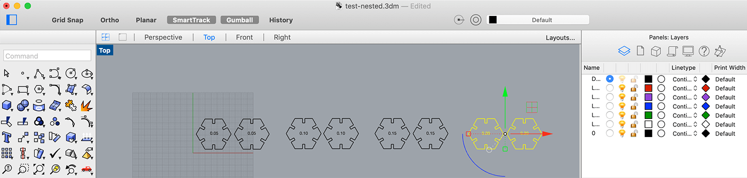
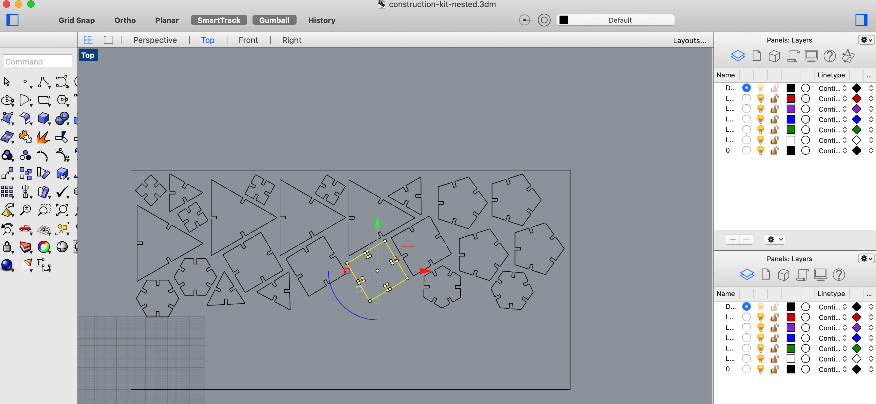
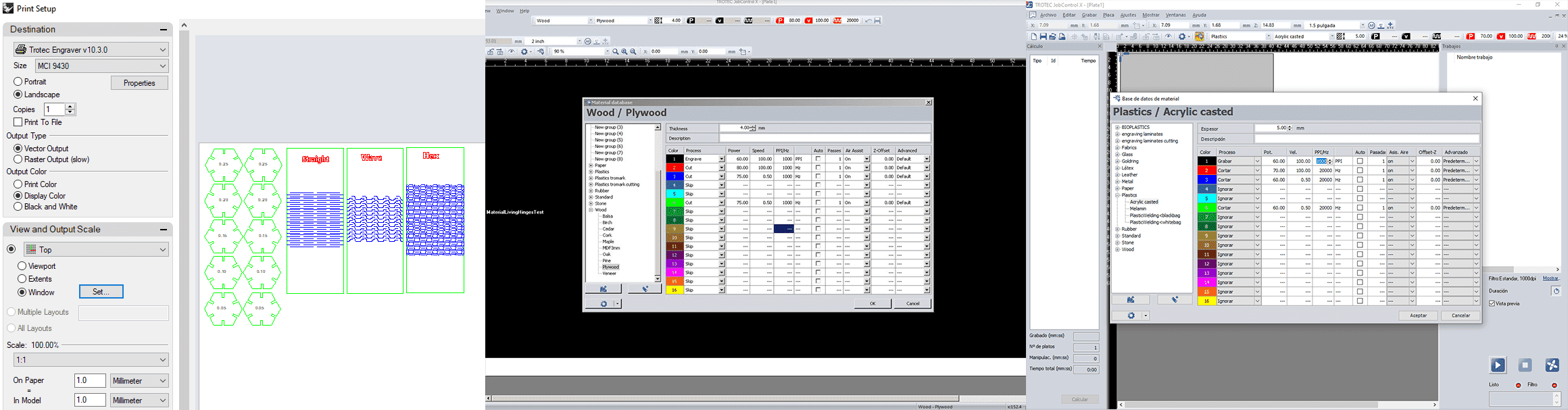
- Nest the pieces in Rhino in order to optimize the position over the cuttable area. We can use DeepNest for this, but I did it manually because I mostly used leftovers from other students.
- Color-code the curves with this execution order: black, red, blue, etc. Press Ctrl + P to preview the files and send it to JobControl
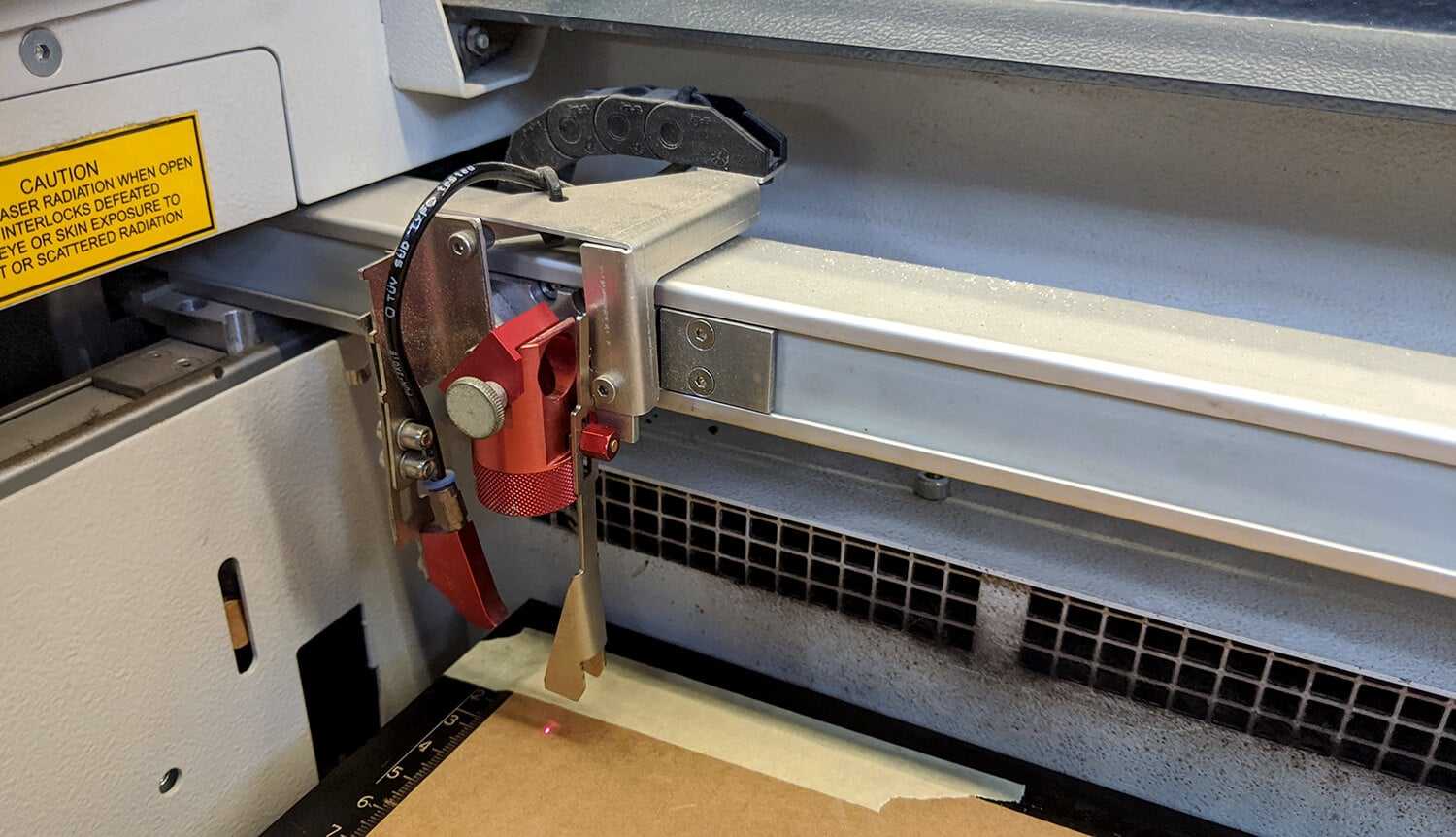
- Manually adjust the focus of the laser beam and use masking tape to fix the position of the cardboard in order to prevent losing focus
- Adjust the position of the job in JobControl and set up speed=1, power=40, PPI/Hz=1000 in Material Settings
- Start cutting!
The cut pieces shown below helped me confirm the kerf width to be used would be 0.15mm in order to assemble 2 pieces securely. The pieces just perfectly joined together without being squeezed or loose. Hence, I modified the parameter in OpenSCAD and continued to cut the rest of my design with that final value.
For this final cut of my construction kit, I utilized the leftovers instead of cutting another whole new 600 x 300mm piece. That's why I had to measure the cuttable area and nested the pieces accordingly.
In addition, I noticed that some bigger pieces had not been completely cut through, and I had to use a knife to get them out. I re-cut some big pieces with cardboard, and instead of increasing power, I reduced the speed to 0.8.
Finally, I had the pieces perfectly joined together!
Final result
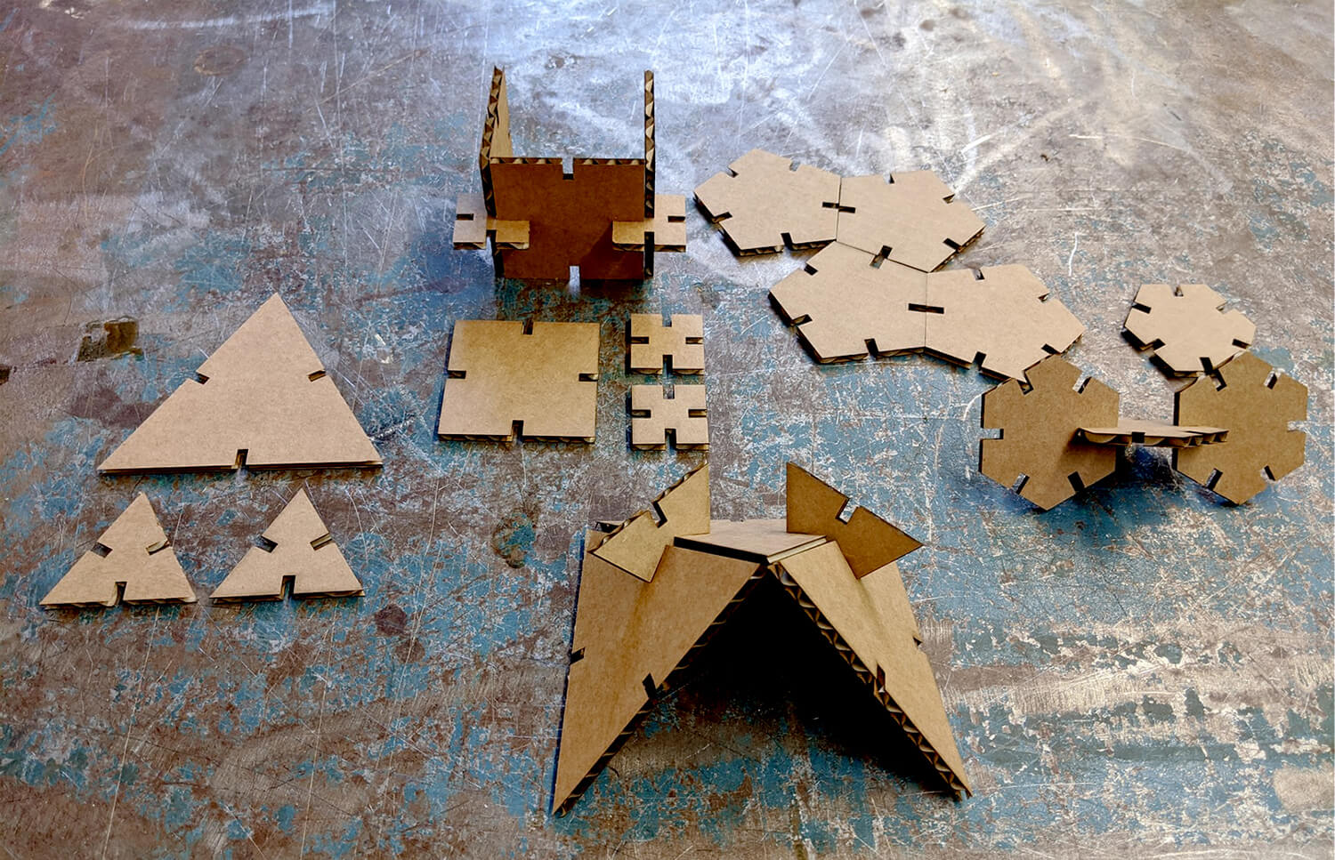
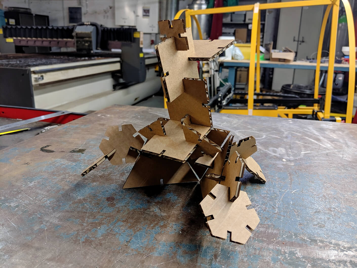
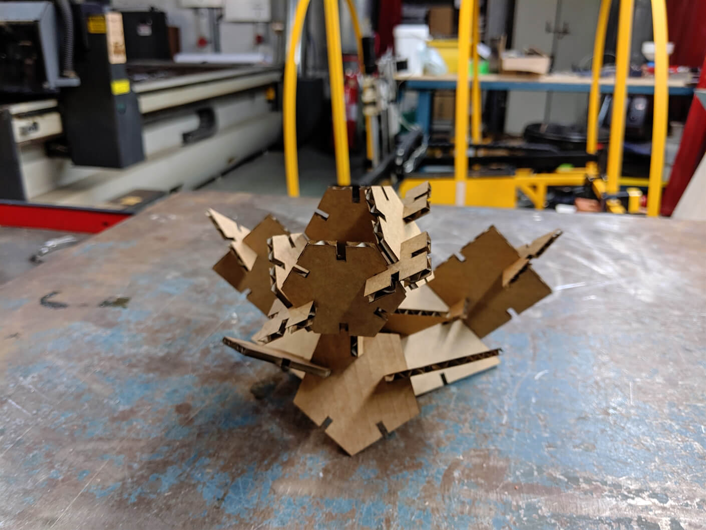
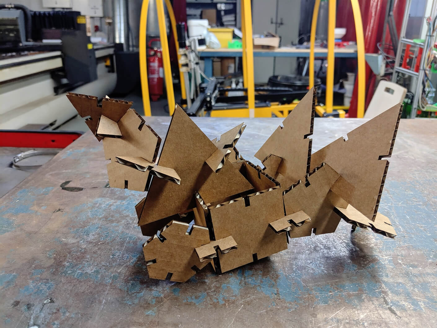
Once I had the laser-cut cardboard pieces in my hands, I tried assembling them randomly. The results were more varied and interesting than I imagined, so I was quite happy with them and I didn't proceed with any further step.
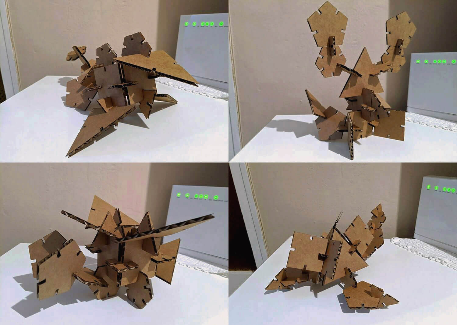
I brought the kit to the landlady where I'm staying. She enjoyed playing with it, and her results were much more impressive. Here we have a resting bird, an angry lobster, a 2-headed monster with wings, and a square-headed scorpio!
Additional test - Joint clearance and living hinges
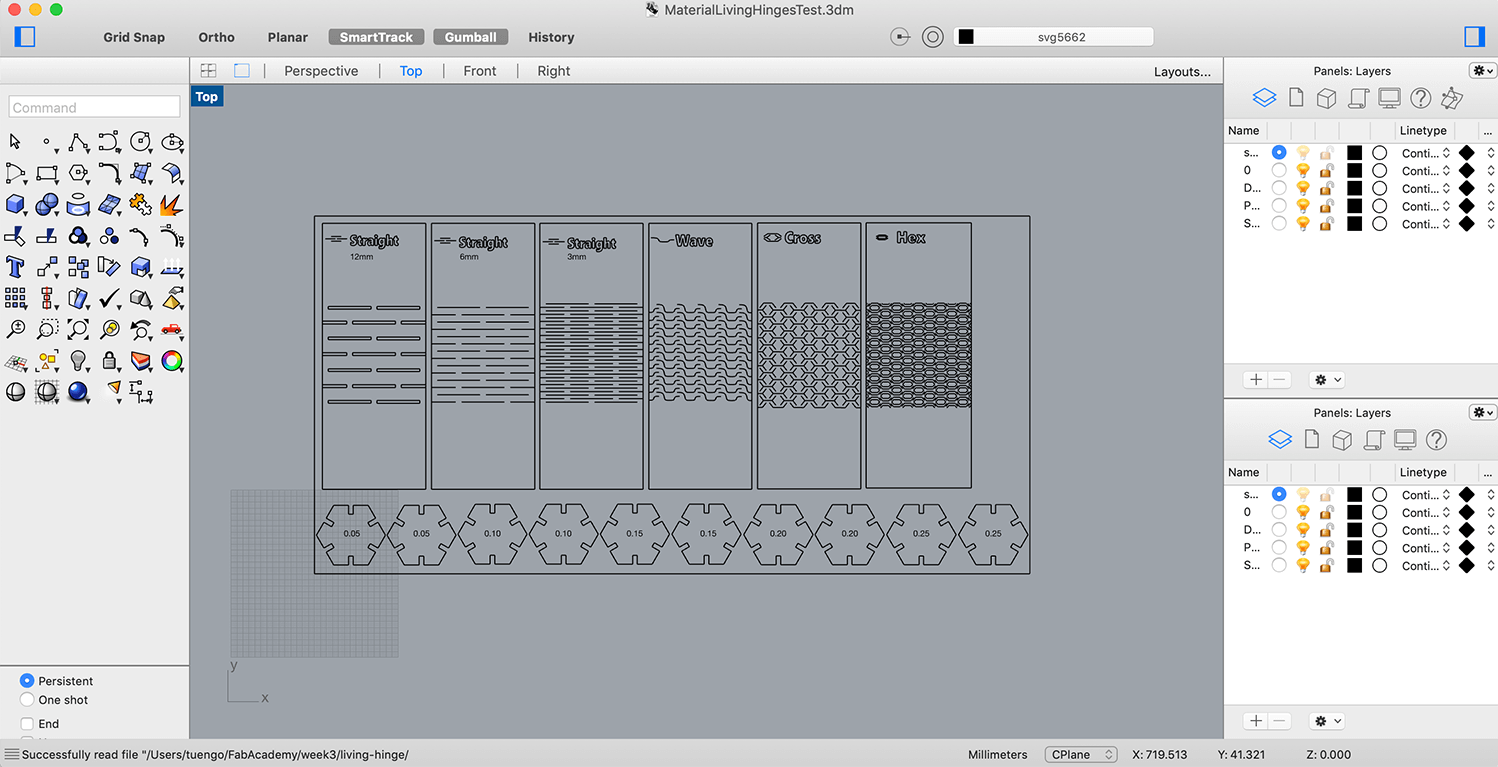
After the regional review, I realized that I didn't proceed with any joint clearance and kerf bending test with other materials rather than cardboard 4mm (which I'm pretty sure I won't use for my Final Project). I also bumped into this article about neater design with living hinges, which is also super tempting. Therefore, I'd like to go a further step by testing the cutting kerf width and the kerf bending capabilities of 2 potential materials for my Final Project: plywood 4mm and acrylic 3mm. I used the same above hexagons to test the kerf width and joint clearance (for acrylic 3mm, I prepared additional hexagons with bigger kerf values: 0.25mm, 0.30mm, 0.35mm and 0.4mm). For testing the kerf bending, I used different living hinge templates which I downloaded from this guy (of course, I modified them a bit).
I used the same TROTEC Speedy 100 machine to cut my test with plywood 4mm. For acrylic 3mm, I used the bigger TROTEC Speedy 400 with these detailed specs:
- Work area: 1,000 x 610mm
- Height: 305mm
- Laser power: 40-120W
The settings I used for plywood 4mm:
- Engrave (Raster): speed=100, power=60, PPI/Hz=1000
- Engrave (Vector): speed=100, power=80, PPI/Hz=1000
- Cut: speed=0.5, power=75, PPI/Hz=1000 (slower speed and lower power than the settings of the group test)
The settings I used for acrylic 3mm:
- Engrave (Raster): speed=100, power=60, PPI/Hz=1000
- Engrave (Vector): speed=100, power=70, PPI/Hz=20000
- Cut: speed=0.5, power=60, PPI/Hz=20000
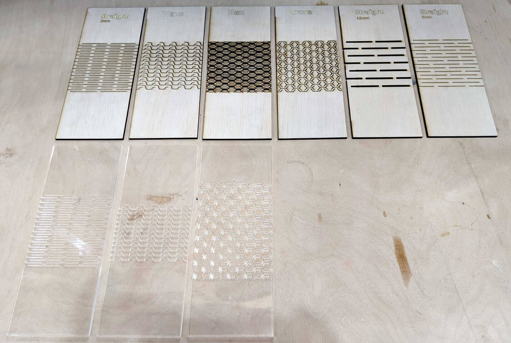
Final cut pieces came out neat for both machines:
Bonus: a video recording the super nice process of laser-cutting cast acrylic:
Result of joint clearance test
The cut pieces shown below helped me confirm the kerf width of plywood 4mm would be 0.15mm in order to assemble 2 pieces securely.
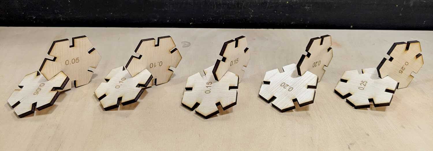
For acrylic 3mm, the joint of the hexagons with 0.40mm kerf width was still barely loose (which surprised me a lot since I didn't expect such a big kerf). Also, the kerf width of each joint seemed to be inconsistent (I assumed that the laser cutter has different performances at different axes). That's why I used a caliper to measure carefully some dimensions, and after doing some annoying maths, I came to a conclusion that the kerf for acrylic 3mm should be somewhere in between of 0.45mm and 0.5mm. However, in case I will go ahead with acrylic for my Final Project, I might need to test it properly again.
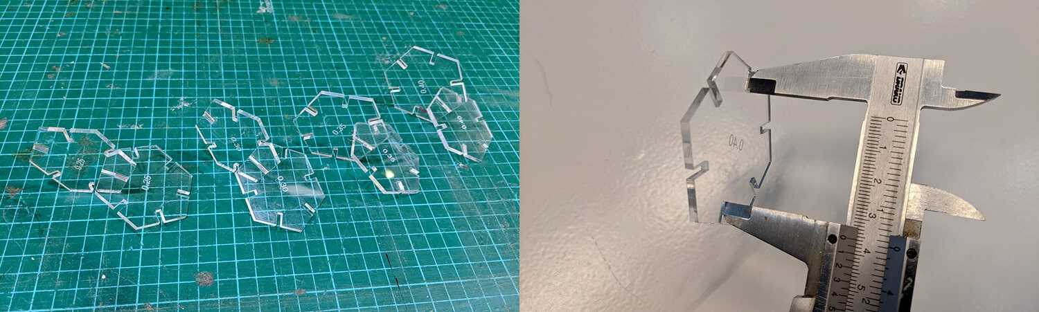
Another thing I noticed after the test was that the surface of the material is also an important factor in making the joint stronger. Cardboard is a soft and flexible material, therefore we can squeeze the parts a bit and they can fit together, and so a slightly tight joint doesn't matter. Plywood is a rigid material, so we need to be a bit more precise. However, the rough surface of plywood can help increase adhesion, which is very helpful in the case of loose joints. For acrylic with a smooth surface, the accuracy of kerf width needs to be increased, since the 2 pieces will slide out very easily if the actual kerf is just slightly bigger than the estimated one.
Result of living hinge test
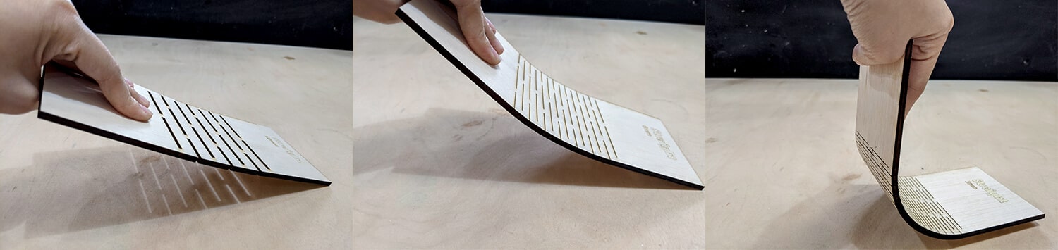
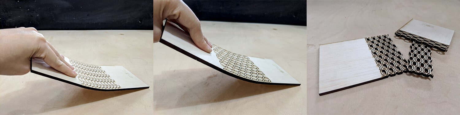
The templates I used for the living hinge test were: straight intersecting lines with different interline gap values of 3mm, 6mm, and 12mm (yeah I know it's stupid to go with 12mm, but it was for the sake of learning); wavy cut lines with 6mm interline; cross/honeycomb cut lines with 6mm interline; and large hexagons/honeycombs with 6mm interline.
Some observations for plywood 4mm:
- Straight intersecting lines: the further apart the single intersecting lines are, the bigger the bend radius will be. It was obvious that the one with 12mm interline cannot be bent at all, and the one with 6mm interline can only be bent insignificantly (less than 45°). The one with 3mm interline seemed to be the best option since the bend radius was really stable and I can bend it up to 165° - almost foldable.
- Wavy cut lines: the interline gap was a bit too big, therefore it can be bent insignificantly. However, it showed quite fair bending capabilities compared to the straight one with similar interline gap.
- Cross/honeycomb cut lines: it offered significant flexibility in other directions, even with a big 6mm interline.
- Large hexagons/honeycombs: the thin interline made the piece broke immediately when being bent. I also think one of the reason was that the pieces were bent in the same direction of the wood fiber.
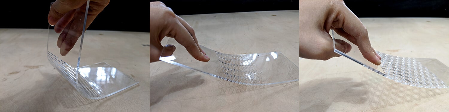
After getting the result of plywood, I modified the design a bit before testing with acrylic: straight intersecting lines with 3mm interline; wavy cut lines with 3mm interline; and large hexagons with 6mm interline. The results looked better, however, the one with straight intersecting lines was still the most flexible one.
Conclusion
Settings for different materials and processes
| Material | Process | Power | Speed | PPI/Hz | Kerf |
|---|---|---|---|---|---|
| Cardboard 4mm | Raster engrave | 60 | 100 | 1000 | - |
| Cardboard 4mm | Vector engrave | 60 | 100 | 1000 | - |
| Cardboard 4mm | Vector cut | 40 | 0.8 | 1000 | 0.15mm |
| Plywood 4mm | Raster engrave | 60 | 100 | 1000 | - |
| Plywood 4mm | Vector engrave | 80 | 100 | 1000 | - |
| Plywood 4mm | Vector cut | 75 | 0.5 | 1000 | 0.15mm |
| Acrylic 3mm | Raster engrave | 60 | 100 | 1000 | - |
| Acrylic 3mm | Vector engrave | 70 | 100 | 20000 | - |
| Acrylic 3mm | Vector cut | 60 | 0.5 | 20000 | 0.45 - 0.5mm |
Living hinges assessment
| Cutting technique | Pliability | Tensile strength | Torsional strength |
|---|---|---|---|
| Straight intersecting lines | Super good | Super good | Good |
| Wavy cut lines | Good | Fair | Fair |
| Cross/honeycomb cut lines | Poor | Fair | Good |
| Large hexagons/honeycombs | Poor | Fair | Poor |
That's it, enough testing with laser-cutting. I'm looking forward to other subtractive CAM techniques that will be introduced in the upcoming weeks. In case I will laser-cut some parts of my Final Project, I will try to test whether I can assemble those parts with 3D-printed parts after doing the tolerance test in the 5th week.