This week's assignment is to characterize the design rules for 3D printing (in-group); to design and 3D print an object that could not be made subtractively (individual); to 3D scan an object (individual).
* All G-CODE, STL, and original editable files can be downloaded here.
* This week's group assignment is to test the design rules for the 3D printers available at Fab Lab Barcelona.
* Besides, we are required to individually design and print something with a standard FDM printer and 3D scan an object - in my case, I chose to scan myself.
* I also attempted to go through another 3D printing technique which is stereolithography with an SLA printer.
3D scanning
Individual assignment - 3D scan myself
Scanning with Kinect and Skanect
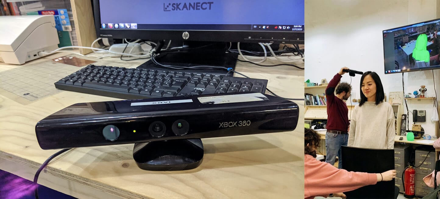
I used a Kinect Xbox 360 V1 to scan myself since I knew it's a common practice by looking at previous alumni's websites. Below are the detailed specs of the device:
- Sensors: color sensor (RGB camera), depth-sensing lenses (IR emitter + IR camera), voice microphone array, tilt motor for sensor adjustment
- Field of view (FoV): 43° vertical x 57° horizontal
- Physical tilt range (vertical): ± 27°
- Depth sensor range: 1.2 - 3.5m
- Frame rate (depth and color stream): 30FPS
The software paired with Kinect that we used to process the scan is Skanect. Here we can find a step by step instruction on using Skanect. Choosing myself as the scanned object means I required further supports from others: someone held and tilted the Kinect vertically (Santi - our instructor), someone rotated me while I was kneeling on the chair (my classmate Hala), and someone documented the process (Zoi - an MDEF student). The reason why I was not sitting on the chair is to avoid having to process the chair from the exported mesh later.
Steps to scan:
- Check the connection between Skanect and Kinect
- Select the Body scene with 1 x 1 x 1m bounding box and start scanning
- Click the record button, rotate and maintain the object to make sure it could be scanned properly.
- Click the button again when finishing.
- Crop the messy bottom of the mesh and ensure a flat base for the model by selecting the Move & Crop feature
- Make the mesh watertight and fill holes by selecting the Fill Holes feature and choosing the Medium option
- Export to
.objor.stl
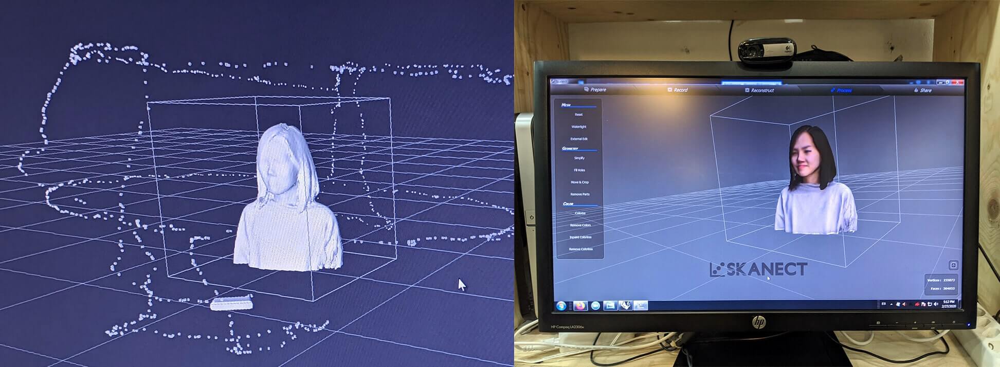
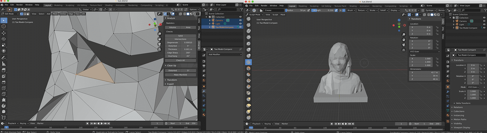
And here is the outcome imported to Blender (the size of the file is too big, therefore I just posted a screenshot here):
Processing the mesh with Blender
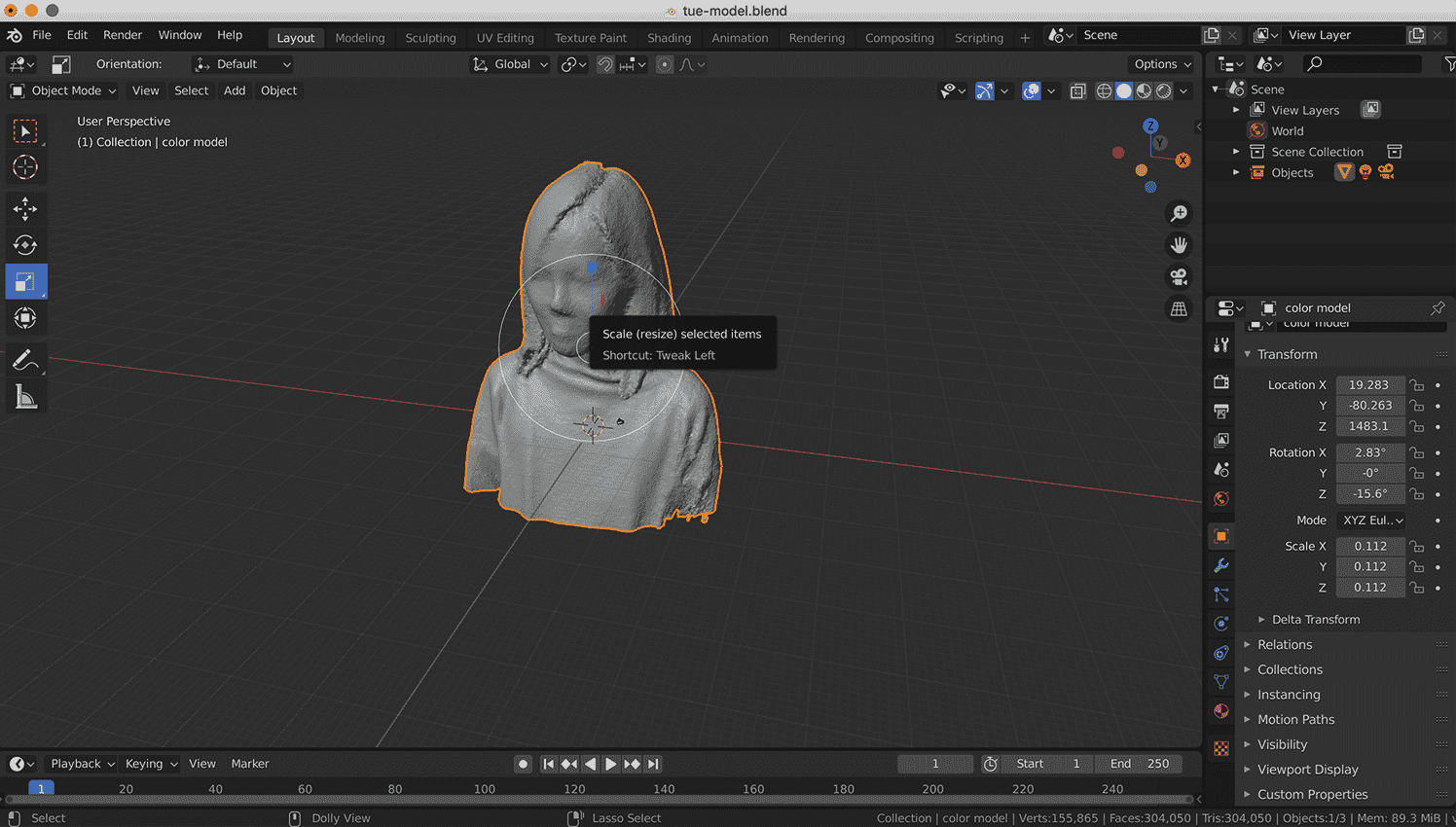
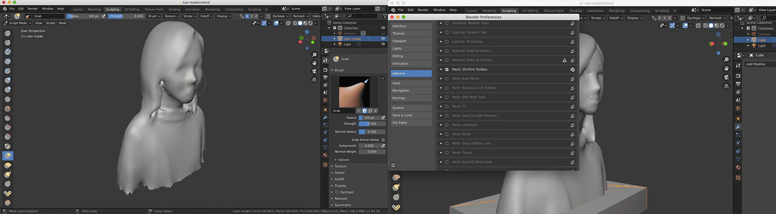
Let's make myself a bit prettier by 3D retouching the outcome! We had a class by Victor Barberan regarding fixing the mesh using Blender. I simply followed his instructions to work on my mess, oh I meant, mesh. Some steps followed (IMPORTANT: following the order can be life-saving. I started sculpting BEFORE switching to Edit Mode and I hit my head to the keyboard soon after):
- In Object Mode: rotate, scale and Set Geometry to Origin
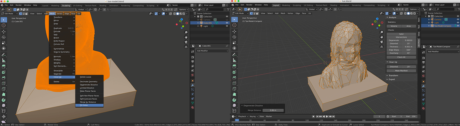
- In Edit Mode: use Select Circle tool to select the exterior faces of my model, hide them, and delete the horrible mess inside. Also, hit space and remove duplicated vertices.
- Select the whole model and go to Mesh > Clean Up. Use Delete Loose to get rid of loose vertices and edges. Select Decimate Geometry and reduce the ratio to collapse edges and to get a less complicated model.
- Activate and install Mesh: 3D Print Toolbox module in User Preferences > Add-ons. Now we can see errors in the mesh that prevent it from being printable (holes, faces normals, self-intersections, manifold errors) and clean them up. In my case, I selected Make Manifold to get rid of distorted edges.
- Go back to Edit Mode: spot holes in the model, select their borders and press Option + F to fill the holes
- Now we can go to Sculpt Mode: fine-tune the model with sculpting tools such as Smooth, Flatten and Grab
- Go back to Object Mode: solidify the object (optional) and add a cube base to the bottom of the model
And let me introduced you to the 3D Tue (not in a perfect state)!
I studied sculpture in college before, so the Sculpt Mode was really tempting to try. I indeed played around a bit by keeping the same amount of triangle faces from the scanning outcome, and fine-tuned the model with other sculpting tools, such as Draw, Blob, Crease, Grab, and Pinch. Of course, the model was way visually prettier and detailed. However, the size of the file was unnecessarily large, and I could not 3D-print it properly since there were so many non-manifold faces and messy layers. Cleaning them up could be a real pain, therefore I decided not to continue with it.
I didn't proceed to print myself, because I would like to allocate more time trying SLA 3D printing technique. In the end, I couldn't make it on time for the additional exploration, but everything is in process ;)
3D printing
First of all, what is 3D printing, or should I say, additive CAM? 3D printing is a technique of adding successive layers of material until an object is created, while subtractive CAM removes material from a larger piece (by cutting, drilling, milling, grinding or turning) to create objects. 3D printing has significant advantages: avoiding the waste of materials and allowing us to create models that would be tricky to be made using subtractive techniques (having undercuts, overhangs, nested parts or complex hollow parts).
Depending on the technology, the 3D printer deposits material (FDM), selectively melts and fuses powder (PBF), or cures liquid photopolymer materials (SLA) to create parts based on the CAM data.
Group assignment - Characterize the 3D printers
We proceeded with our tests using the most common printing technology: FDM. Fused Deposition Modeling (FDM) belongs to the material extrusion family of 3D printing techniques. In FDM, the materials used are thermoplastic polymers and come in a filament form. Once the nozzle has reached the desired temperature, the filament is fed to the extrusion head and in the nozzle where it melts. The extrusion head is attached to a 3-axis system that allows it to move in the X, Y and Z directions. The melted material is extruded in thin strands and is deposited layer-by-layer in predetermined locations, where it cools and solidifies. When a layer is finished, the extrusion head moves up and a new layer is deposited. This process is repeated until the part is complete.
Before participating in the group test, I took a look at this useful article in order to understand what we were going to test.
First test - General design rules
I teamed up with David Prieto and Antoine Jaunard for the first test. We used the Creality CR-10 S5 printer to print this test file using 1.75mm PLA. The detailed specs of the machine:
- Printing technology: FDM
- Printing size: 500 x 500 x 500mm
- Printing accuracy: ± 0.1mm
- Nozzle diameter: standard 0.4mm (can be changed to 0.3 or 0.2mm)
- Printing speed: normal 80mm/s, max 200mm/s
- Materials: PLA, Copper, Wood, Carbon Fiber, etc.
- Printing method: SD card, USB
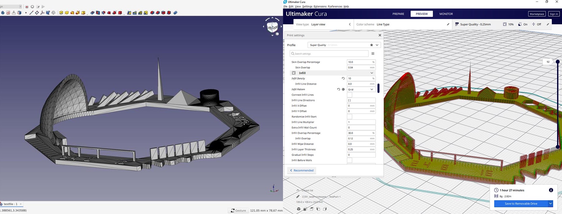
We used Ultimaker Cura in order to slice the model, to modify some important settings for the 3D printing process, and to generate a .gcode file. G-code is the language through which we can communicate with computer-controlled machine tools (in this case, the 3D printers) and give them instructions on what to do. The Cura apps installed in Fab Lab Barcelona's computers have the profiles of all available printers with tons of proper settings. However, we had to, and should only, modify some settings to manipulate the printing time:
- Layer height: 0.2mm. The thinner the layer, the more detailed the result, and the longer the total printing time. We chose 0.2mm for the tests to get a more delicate result.
- Wall thickness: 0.8mm - usually double the size of nozzle diameter because we generally print with two shells: one for inside and one for outside.
- Infill density: 10% - Infill pattern: Grid. Infill is a repetitive structure used to fill the empty space in a print. A high infill density can make the printing time longer and the outcome heavier and more rigid. In the case of printing solid constructible parts, a higher infill density is recommended.
- Print speed: 60mm/s. The lower the speed, the finer the outcome.
- Support: not in this case, but we might need to generate a support structure under the model in order to prevent the material from falling down when it comes to large overhang angles.
Here you go the video recording the printing process:
The printing was done in 1 hour 27 minutes:
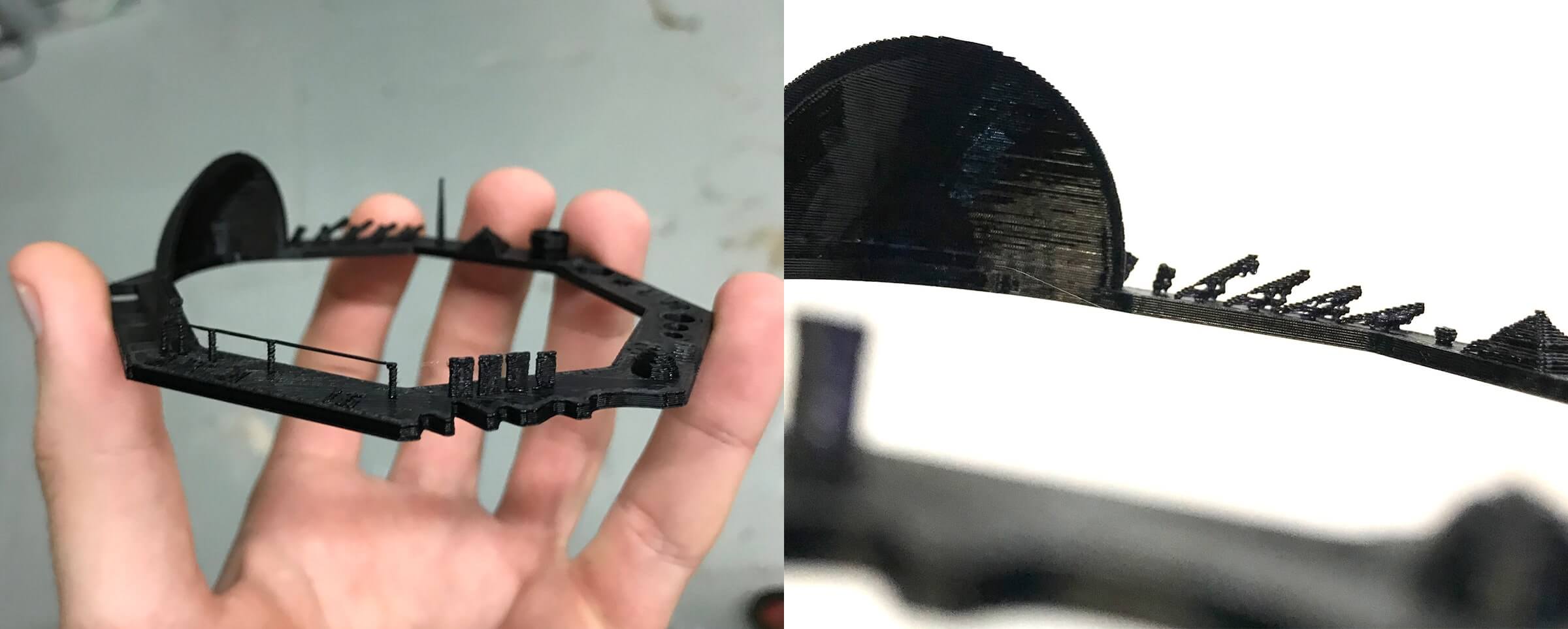
As per the images above, the quality of the print was quite good, many details were respected. Here are the test results after I measured carefully the outcome with the caliper:
- Quality of wave (rounded print), star (sharp edges), CtrlV (complex shapes): slightly acceptable
- Dimension accuracy: + 0.08mm (x,y) and + 0.1mm (z)
- Tolerance (calculated by measuring holes' diameters): 0.15 - 0.25mm, which means minimum clearance is around 0.3 - 0.5mm
- Minimum hole size: all passed, up to 0.6mm
- Minimum wall thickness: 0.1mm
- Minimum distance between walls: 0.6mm
- Horizontal surface finish: quite smooth, all passed (both spheres and pyramids)
- Overhang angles: perfectly nice at 35°, slightly acceptable up to 60°
- Bridges: all passed, up to 16mm length
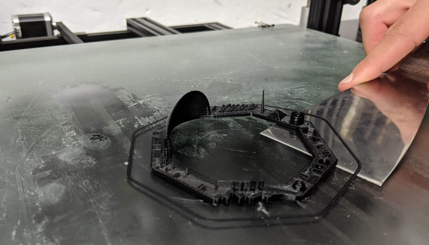
Second test - Tolerance and joint clearance
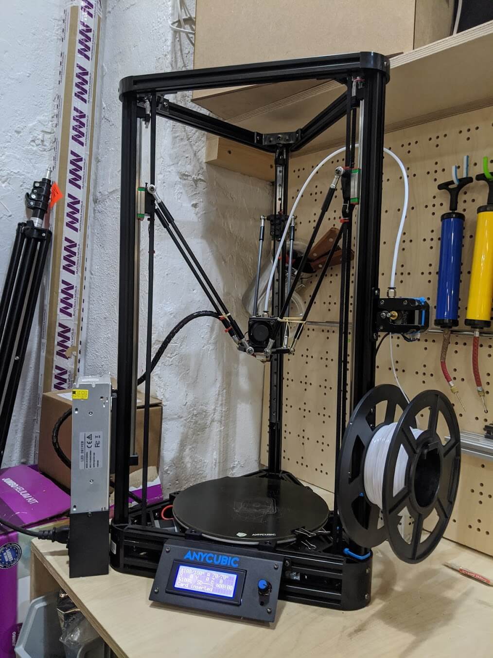
For the second test, I teamed up with Roger Anguera, Bruno Molteni, David Prieto, and Lynn Dika. We used the Anycubic Kossel Plus printer, and our Fab Lab Manager Mikel Llobera guided us through the process. The detailed specs of the machine:
- Printing technology: FDM
- Printing size: 230 x 180 x 300mm
- Nozzle diameter: 0.4mm
- Printing speed: 20 - 80mm/s
- Materials: PLA, ABS, HIPS, Wood, etc.
- Printing method: SD card, USB
The estimated printing time was too long, hence, we had to scale-down the object to 70%. We then used the same settings as the first test. The printing was done in 1 hour 35 minutes:
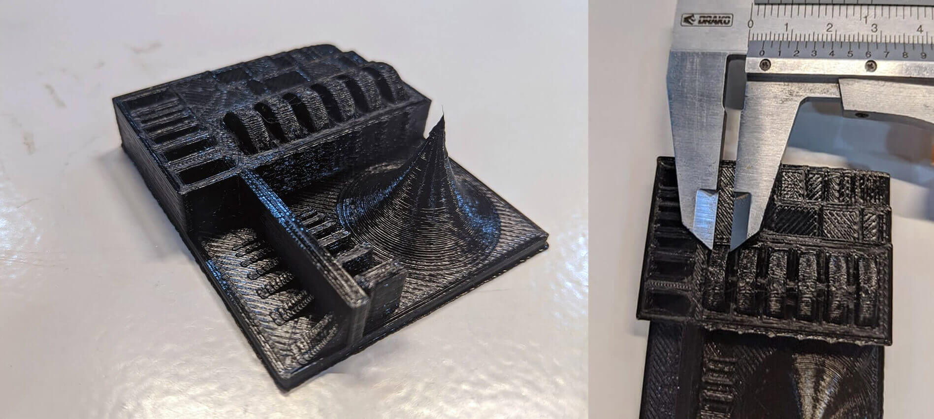
Generally, the quality of the print was poorer compared to the one printed by the Creality printer. Here are the detailed test results measured by the caliper:
- Dimension accuracy: + 0.15 - 0.2mm (x,y,z)
- Tolerance (calculated by measuring holes' sizes): 0.25 - 0.3mm, which means minimum clearance is around 0.5 - 0.6mm
- Minimum hole size: up to 0.7mm. Smaller than this, the printer ignored the walls and printed a big hole.
- Minimum wall thickness: 0.1mm
- Minimum distance between walls: 0.3mm
- Horizontal surface finish: lower quality than the outcome of the Creality printer
- None of the wheels could be able to move, and the reason might be because we scaled-down the object to 70%.
What I personally learned
- Pay attention to laws of gravity. We cannot print a piece in mid-air, and models must lie flat on the build plate or be supported.
- The model must fit within the printer’s working area. The very first thing we need to ensure in Cura is the printer we're going to use!
- Heat and curing may cause warping and often the initial base layer of a print is very easy to mess up. In order to mitigate this concern, we should use a brim or raft plate before printing the first layer of the actual part.
- To achieve longer bridges, we can slow the print speed down and reduce the temperature. The faster the speed, the greater the chances are for filament sags. This is because the capability of printing horizontal spans is mostly affected by the quality of the material and how close the bridge is to the heated bed.
- Tolerance is an important parameter while designing assembled parts, and it could be slightly different when we use different printers or materials. For press-fit joints where parts are held together by friction, allow for a 0.25mm offset from the interior parts. For sliding-fit/free-fit joints that allow movement or rotation, allow for 0.5mm offset from each side.
- Be careful when scaling objects with nested parts. Use the Preview mode in Cura to make sure we're not going to mess up with the designed joint clearance.
Individual assignment - Design and print using FDM printer and PLA filament
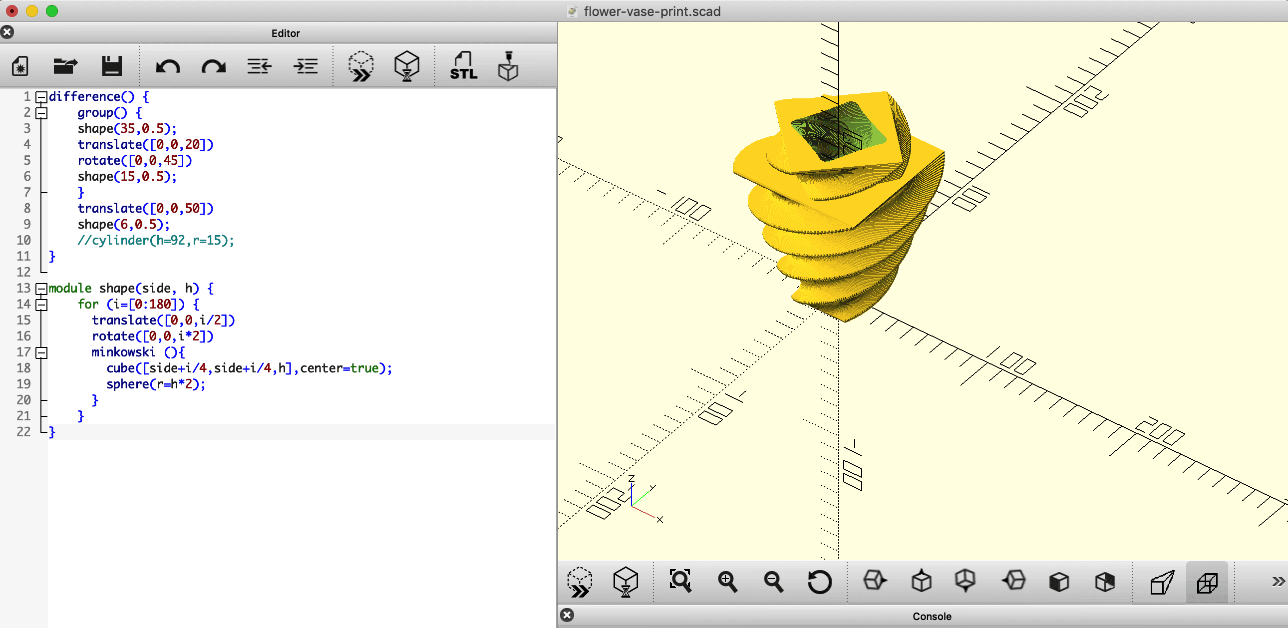
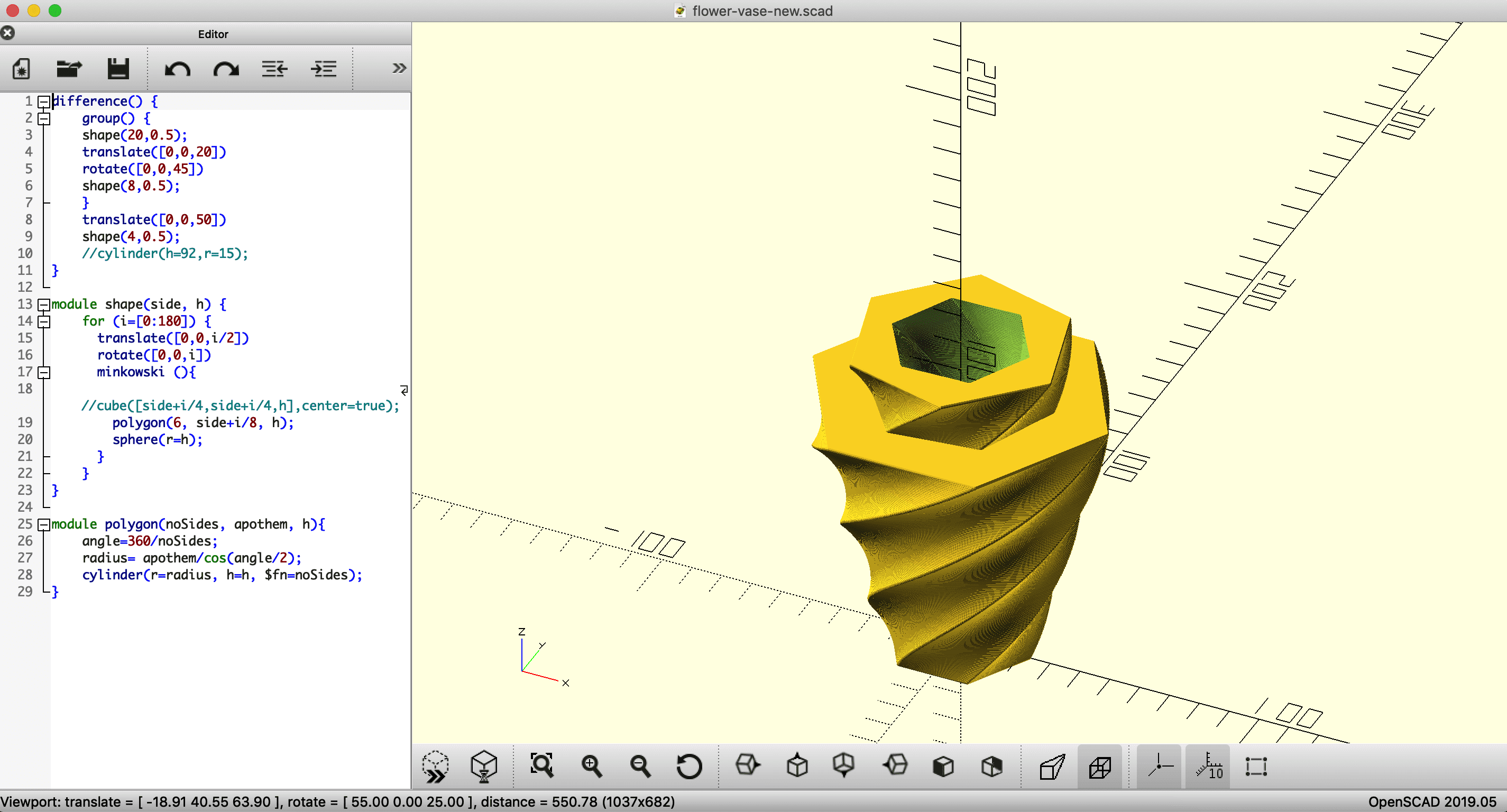
Designing with OpenSCAD
I utilized a flower-shaped vase I designed in the 2nd week since it can be considered as an object that cannot be made subtractively (having overhangs and undercuts). My vase was designed in OpenSCAD, and I basically modeled a thin cube, then continuously cloned, rotated, enlarged and moved it up x 180 times to generate the base module shape(). 3 shape() modules were combined and subtracted to form the final model. In order to make sure of the ability to stand still of the vase as well as to reduce the total size, I modified it a bit by lessening the additional size of the cloned cubes.
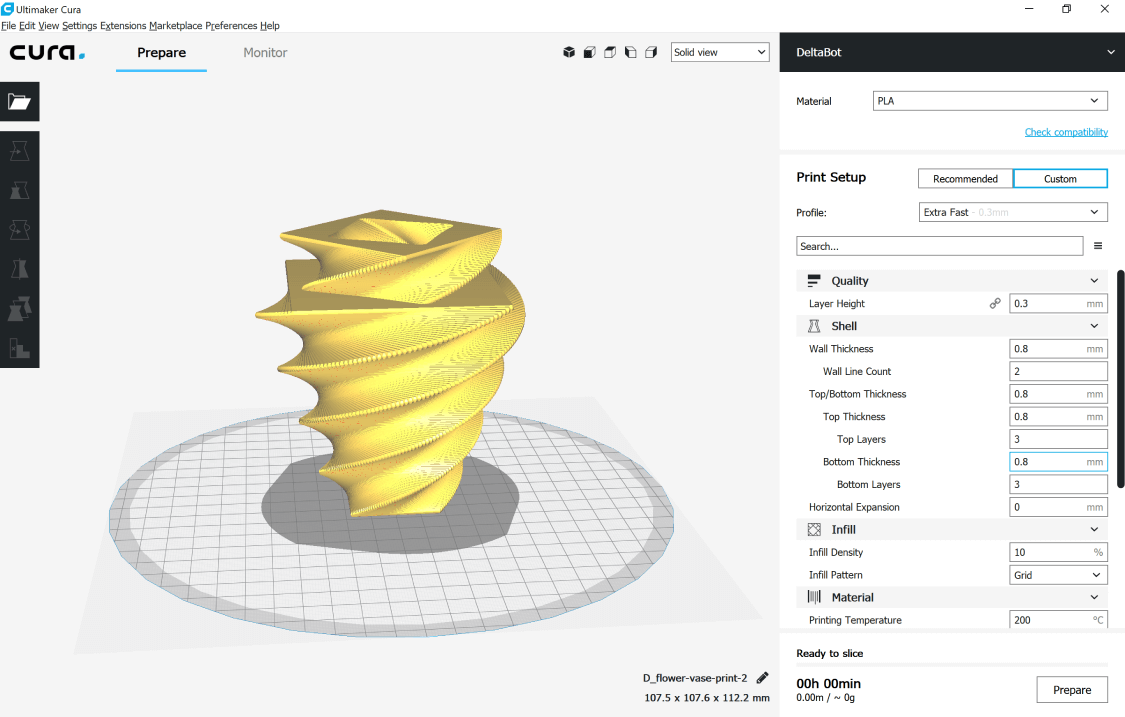
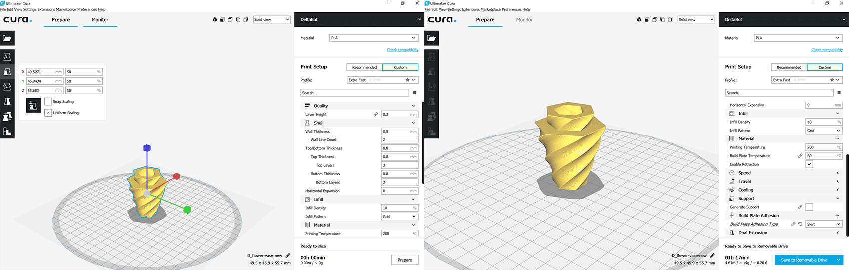
Slicing with Cura
After exporting the .scad file to .stl, I started slicing the object in Cura. Since my design was more about a nice shape rather than an object with too many details, I used these settings:
- Layer height: 0.3mm
- Wall thickness: 0.8mm
- Print speed: 80mm/s
- Infill density: 10% - Infill pattern: Grid
The estimated printing time was more than 3 hours, therefore I had to reduce the size of the model by 50% directly in Cura, using the Snap tool. Ready to print!
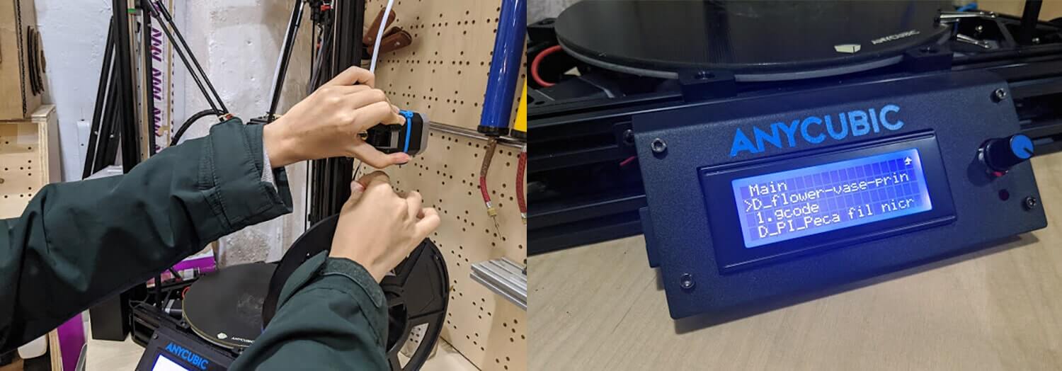
Printing with PLA filament
I used the same Anycubic Kossel Plus printer to print my vase since we can use it without reservation. Josep guided me through some essential steps:
- Export the
.gcodefile and save it to the SD Card of the printer - In case we need to change material, pre-heat the machine (Prepare > Preheat PLA) up until 205-210°C and we can remove the broken filament
- Put SD card in and select Print from SD, the choose the
.gcodefile and start printing! - Check if there is any problem with the initial layer, or whether the printer is printing in the air. We might need to calibrate the Z-axis or work on leveling the bed, and I usually ask our instructor Eduardo Chamorro or Mikel Llobera whenever it comes to this task.
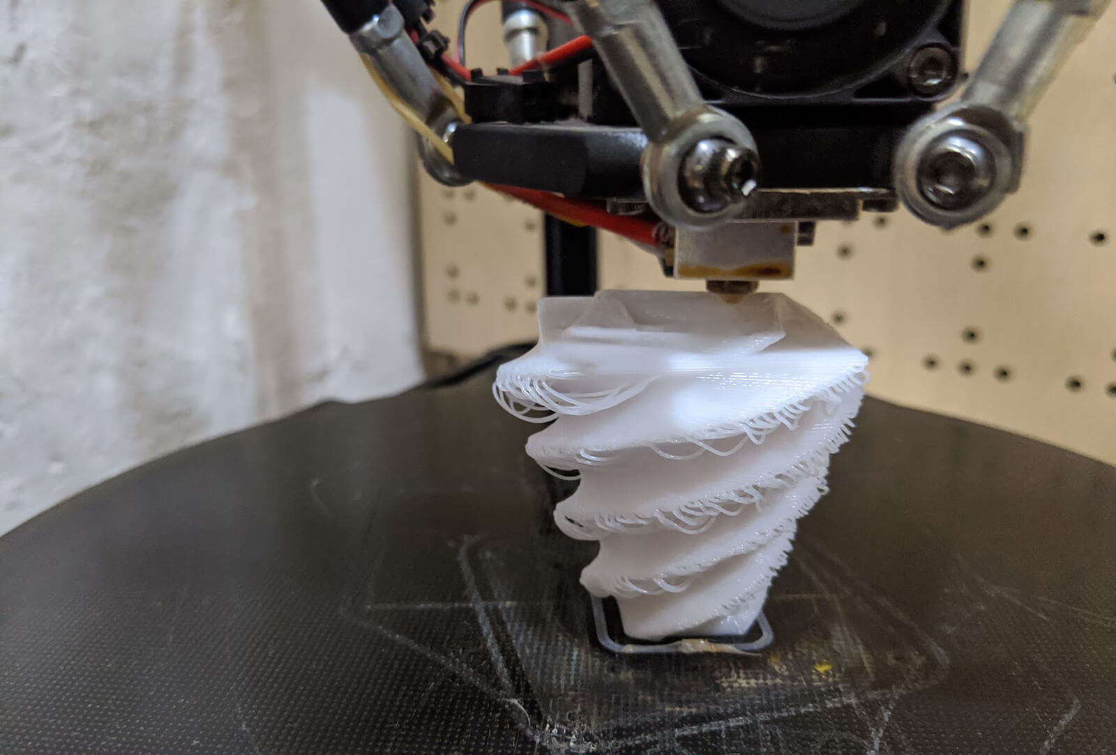
I then had some problems with the printing process. Although I reduced the overhang angle from the bottom of the vase to its top, the overhang angles between the twisty parts were obviously too big and the printer started to print in the air. In order to both reduce the size and maintain a nice shape, I modified the cube in my design to a hexagon cylinder by utilizing the module used in the 3rd week.
Then I faced the 2nd and 3rd failures. For the first print, I only selected the Skirt option in Plate Adhesion and the adhesion was fine. However, for the next print, the model started moving while being printed. I tried the second time by selecting the Brim option, but things didn't go well either. In the end, I had to print the 4th time with the option Raft selected.
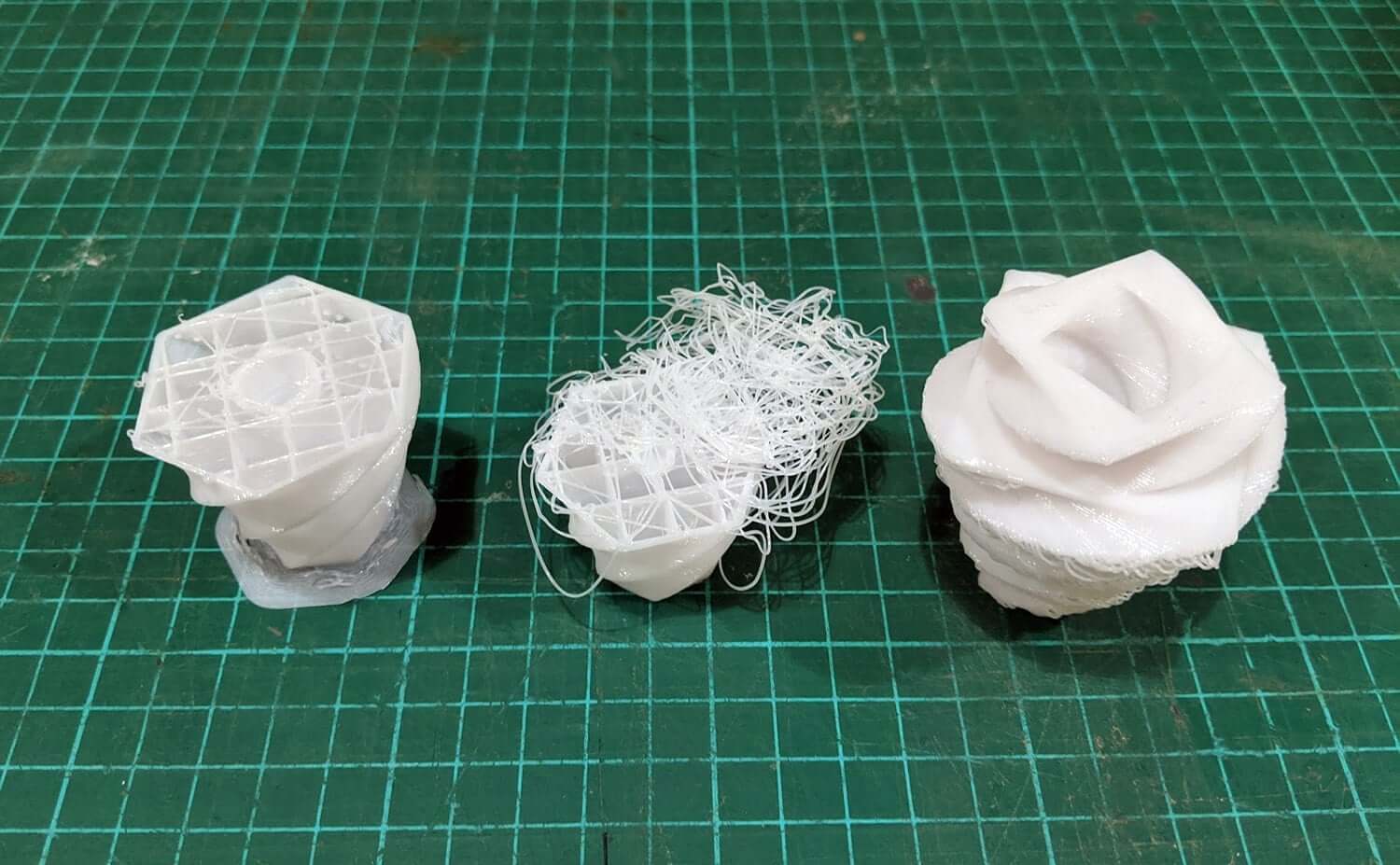
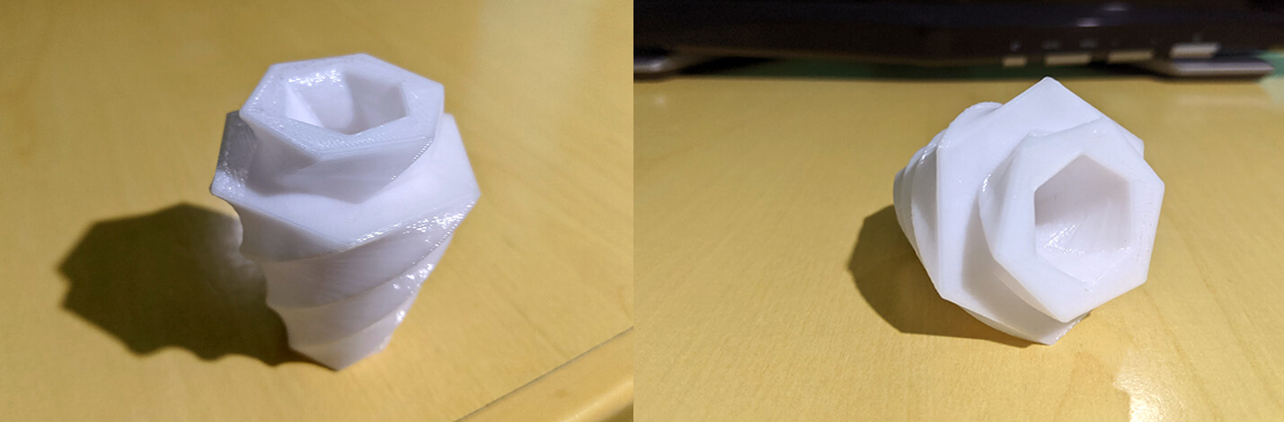
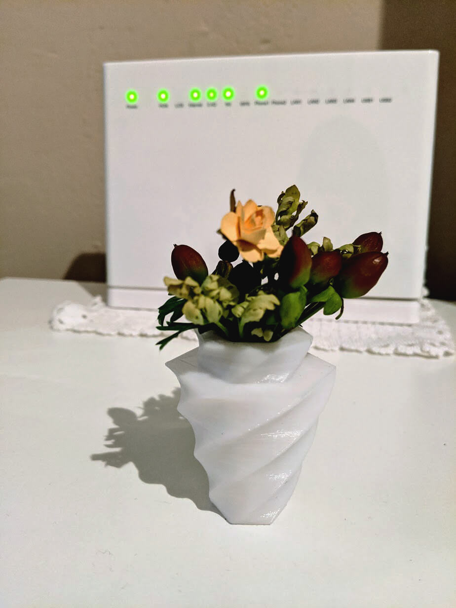
Finally, I had the vase perfectly printed!
Final result
I brought the vase to the landlady where I'm staying, and here you go the hero shots of the final result:
Additional test - Stereolithography using SLA printer and UV resin
Stereolithography (SLA) belongs to the Vat Photopolymerization family of 3D printing techniques. In SLA, an object is created by selectively curing a polymer resin layer-by-layer using an ultraviolet (UV) laser beam. The materials used in SLA are photosensitive thermoset polymers that come in a liquid form. The build platform is first positioned in the tank of liquid photopolymer (UV resin), at a distance of one layer height for the surface of the liquid. Then a UV laser creates the next layer by selectively curing and solidifying the resin. The laser beam is focused on the predetermined path using a set of mirrors, called galvos. The whole cross-sectional area of the model is scanned, so the produced part is fully solid. When a layer is finished, the platform moves at a safe distance and the sweeper blade re-coats the surface. The process then repeats until the part is complete.
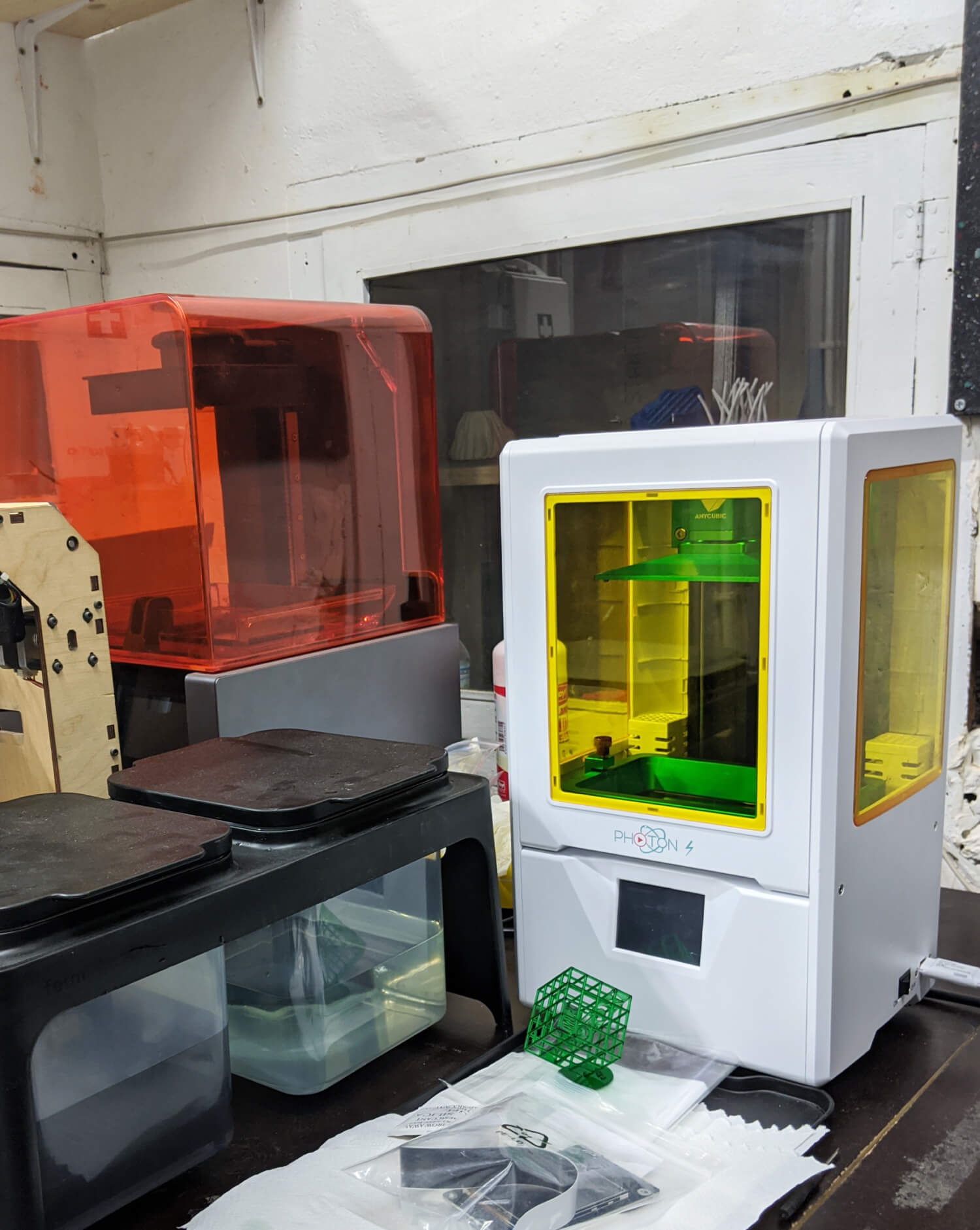
At Fab Lab Barcelona, we have some Formlabs SLA printers and a new Anycubic Photon S. The Formlabs ones were being calibrated, therefore I asked Mikel to let me join him in testing the exposure time of the Photon S printer. Some basic specs of the machine:
- Printing technology: SLA
- Printing size: 115 x 65 x 155mm
- Printing accuracy: ± 0.01 - 0.1mm
- Light source: UV integrated light
- Layer height: 25 - 100um.
- Printing speed : 20mm/h
- Included material: 405um Resin
- Printing method: SD card, USB
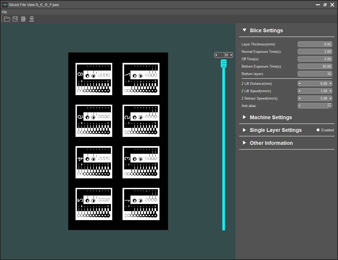
We tried to use this file to test the printer. R_E_R_F (Resin Exposure Range Finder) is a feature provided by Anycubic with which we can find the correct exposure time for any given resin. When any sliced file with the name R_E_R_F.pws is printed on a Photon S, it divides the platform into 8 equally sized sections and exposes each section for a progressively longer time. If we place 8 copies of the same model in those sections, we can compare different exposure times, and thereby decide which time gives the best results.
However, the estimated printing time was much longer than the FDM printers, and the people at Fab Lab Barcelona were about to clean up the 3D printing room and calibrate all the printers. Since it's better to do the test under the supervision of Mikel, we had to delay the test until we can find a better time slot and the machines are ready.
Conclusion
Additive vs. Subtractive CAM
Things I like about 3D printing:
- Avoiding material waste
- Ability to design more complex objects without being brain-tangled while unfolding the design from 3D to 2D
- Somehow somewhat, fewer constraints
Things I wish 3D printing could match subtractive techniques:
- More precise tolerances
- Better surface quality
- Lack of suitability for mass production
Design rules for FDM printers
| Machine | Settings | Dimension accuracy | Minimum clearance (Press-fit) | Minimum clearance (Free-fit) | Minimum hole size | Minimum wall thickness | Minimum distance between walls | Maximum overhang angle | Maximum horizontal span |
|---|---|---|---|---|---|---|---|---|---|
| Creality CR-10 S5 | Layer height: 0.2mm - Infill: 10% | + 0.08mm (x,y) and + 0.1mm (z) | 0.3mm | 0.6mm | 0.6mm | 0.1mm | 0.6mm | Up to 55° without support, preferably 35° | 16mm |
| Anycubic Kossel Plus | Layer height: 0.2mm - Infill: 10% | + 0.15 - 0.2mm (x,y,z) | 0.5mm | 1mm | 0.7mm | 0.1mm | 0.3 mm | 45° | - |
3D printing techniques assessment
| Technique | Materials | Printers | Dimension accuracy | Surface finish | Supports required | Lead time | Post-processing techniques | Fragility | When to use |
|---|---|---|---|---|---|---|---|---|---|
| FDM | PLA, ABS, Nylon, etc. | Anycubic Kossel, Creality, Prusa i3 | ± 0.08 - 0.2mm - Lower dimension accuracy | Lower quality of surface finish | Only required when there are joints or large overhang angles | Relatively shorter | Not always required - sanding, priming, cold welding, vapor smoothing, epoxy coating, etc. | More rigid | Rapid, low-cost prototypes and precision is not crucial |
| SLA | Photopolymer resins (thermosets): clear, flexible and castable | Formlabs, Anycubic Photon | ± 0.01 - 0.1mm - Very high dimensional accuracy and intricate details | Very smooth surface finish | Always required | Relatively longer | Always required - sanding, spray coating, mineral oil | More brittle | Visual prototypes with fine details and strength/durability is not crucial |
That's it, enough testing with 3D printers. The next step is to design the physical parts of my Final Project and to see how can I assemble parts made with subtractive and additive techniques. Before doing that, I still need to make it clear about how I can connect the modules physically, electronically and informatively. Hence, I will delay the task a bit and update later on the Final Project page.