This week's assignment is to characterize the design rules for PCB production (in-group); to mill, solder and test an in-circuit programmer (individual).
* All RML files can be downloaded here.
* To me, electronics is a whole new world, and therefore I need to go through tutorials about basic concepts regarding electronic components and circuits.
* This week's group assignment is to mill a line test in order to understand the machining process.
* I need to individually make an ISP, and I randomly chose the FTDI SERIAL board and the UPDI adapter. I also attempted to use another method for fabricating PCBs.
Understanding electronics and the boards
Yes, you're right, I'm that type of person who needs to understand what I'm doing before doing it. After digesting notes from Oscar's classes, I followed this tutorial to organize better all pieces of knowledge. Allow me to go through a very long note without any images attached, or go straight to the assignments below.
Electricity and how it works
- Voltage (V) is the measurement of electrical potential produced by electricity sources. Higher voltage means the electricity is being "pushed" harder through a circuit. Voltage is measured in volts (V).
- Electricity needs to flow to do anything useful. Electricity will flow from a higher voltage to a lower voltage. If we create a conductive path (for example, copper wire) between a higher voltage and a lower voltage, electricity will flow along that path. Current (I) is the rate at which charge is flowing. A higher current means more electricity is flowing. Current is measured in amperes (A).
- Resistance (R) is the tendency of a certain material to resist the flow of charge (current). Higher resistance means it is more difficult for electricity to flow. Resistance is measured in ohms (Ω).
- Ohm's law equation: V = I x R
- There are two types of electrical sources: alternating current (AC) and direct current (DC). With AC, the direction electricity flows throughout the circuit is constantly reversing. With DC, electricity flows in one direction between power and ground. DC voltage sources always have two sides, with the positive side having a higher voltage than the negative side.
Circuit and PCB
- An electronic circuit is a structure that directs and controls electric current to perform various functions including signal amplification, computation, and data transfer. Conductive wires or traces are used to connect the components to each other. However, a circuit is complete only if it starts and ends at the same point, forming a loop.
- If we insert something useful - which we call component or load (since they're parts of a circuit that consume electricity) - into the circuit like an LED, the flowing electricity will do some work, like lighting up that LED. Complex circuits have different loads such as resistors, capacitors, diodes, and transistors.
- A short circuit is created when a wire is connected directly from the positive to the negative side of a power supply. This is bad because if there is no load to restrict the current flow, there won't be anything to slow down the current, and it will try to be infinite. This could cause the wire to burn up, damage the power supply, or drain the battery. It is very important to prevent short circuits by making sure that the positive voltage is never wired directly to ground (the negative terminal).
- The opposite of a short circuit is an open circuit. This is a circuit where the loop isn't fully connected. If the circuit doesn't work, the most likely cause is an open circuit. This is usually due to a broken connection or a loose wire.
- A printed circuit board (PCB) connects components using conductive tracks and pads etched from a layer of copper laminated onto a non-conductive substrate. Components are directly soldered onto the surface of the pads (SMD), or placed into drilled holes on a bare PCB (through-hole).
Ways to wire components
- Series: components are wired one after another. Electricity passes through one thing, then the next thing, then the next, and so on.
- Parallel: components are wired side by side. Electricity passes through all of them at the same time, from one common point to another common point.
Basic components
- Resistors (R): They add resistance to the circuit and reduces the flow of electrical current. The resistance values are measured in ohms (Ω). Resistors of over 1000Ω are typically shorted using the letter K. Resistors have plenty of applications, but the most common ones are limiting current flow and dividing voltage. Sometimes, a particular part of a circuit such as a micro-controller may need a lower voltage than the circuit itself, and this is where a resistor comes in.
- Capacitors (C): They ensure a steady electrical flow by storing electricity and discharging it into the circuit when there is a drop in electricity. In simple terms, they work as small rechargeable batteries that store electricity. However, unlike batteries, they can charge and discharge in the split of a second. Capacitance is the amount of energy stored in a capacitor and is measured in Farads( pF, nF, uF). These are often used interchangeably and that’s why a conversion chart is handy.
- Diodes (D): They only allow electrical current to pass through them in one direction in order to prevent electricity from flowing in the wrong direction. They are commonly used to convert an AC into a DC or protect the loads from reverse connections. LED is a light-emitting diode that will emit light when electricity flows through it.
- Transistors (T): They turn current on or off when triggered by an electric signal by taking in a small electrical current at a base pin and amplifying it such that a much larger current can pass between the collector and emitter pins. Designers often use a transistor as a switch because unlike a simple switch, it can turn a small current into a much larger one.
- Integrated circuit (IC): An integrated circuit is an entire specialized circuit that has been miniaturized to fit onto one small chip. Each leg of the chip connecting to a point within the circuit.
Micro-controller and micro-processor
- Micro-processor: is an IC that has only the CPU inside them. RAM, ROM, and other peripherals must be added externally to make them functional. Microprocessors perform unspecific tasks such as developing software, games, websites, photo editing, creating documents, etc. The relationship between input and output is not defined. They need a high amount of resources like RAM, ROM, I/O ports, etc.
- Micro-controller: is an IC containing a processor and ROM. We can consider a micro-controller as a mini programmable computer. Micro-controllers are dedicated to one task and run one specific program, for example, keyboards, mouse, remote, microwave, mobiles, watches, etc. The relationship between input and output is specifically defined. The ROM is used to store the program instructions that are rarely changed during the life of the system, sometimes known as firmware.
- A micro-controller is supposed to be able to receive power, input signals, and send outputs to the outer world. Because of that, a micro-controller has a set of input and output pins that can be used to interact with the systems it controls and other micro-controllers. A digital pin is able to detect whether there is a voltage present on a pin or not. An analog pin is connected to an internal ADC (Analog to Digital Converter) and can measure the actual voltage on the pin. Input pins are used to read the logic state on some devices (“1” or “0”). Output pins are used to send logic states to some devices.
Communication between circuits
In order for individual circuits to transfer information, they must share a common communication protocol. There are 2 types of communication protocol: parallel and serial.
- Parallel interfaces transfer multiple bits at the same time. They usually require buses of data - transmitting across 8, 16, or more wires. Parallel communication is fast, straightforward, and easy to implement. But it requires many more input/output lines which can become impractical.
- Serial interfaces stream their data, one single bit at a time. These interfaces can operate on as little as 1 wire, usually never more than 4 wires. The main advantage of serial communication is the cheaper cost of the entire embedded system and the ability to exchange data over a long distance. Some examples of serial communication protocols: SPI, UART, I2C, etc. Here we can find more detailed information about the differences between them.
Available ISPs at Fab Lab Barcelona
In-circuit programmer (ICP): also known as in-system programmer (ISP) or serial programmer, allows micro-controllers to be programmed while installed in a complete system, rather than requiring the chip to be programmed prior to being installed. Micro-controllers are usually programmed through an ISP unless there is a bootloader (a piece of firmware) in the micro-controller that allows installing new firmware without the need of an external programmer.
For the different types of chips, there are different dedicated hardware programmers that allow them to communicate with the outside world. At Fab Lab Barcelona, we have:
- FabISP programmer: an ISP for AVR micro-controllers, designed for production within a Fab Lab. Programming can be done through avrdude.
- FTDI SERIAL chip and UPDI adapter. The FTDI is a USB to Serial converter which allows for a simple way to connect TTL interface devices to USB. UPDI is an interface for external programming and on-chip debugging of newer ATtiny and ATmega devices. The UPDI adapter basically connects the programming pin of the chip to the computer. Programming can be done using pyupdi.
- CMSIS-DAP chip and SWD adapter. CMSIS-DAP is an on-board interface chip, providing direct USB connection from a board to a debugger running on a host computer on one side, and access the DAP of a micro-controller via 5-pin JTAG or 2-pin SWD on the other side. Programming can be done using edbg.
That's it, enough knowledge for this week. In 2 weeks, I will try to learn more about how to understand circuit diagrams and how to design a circuit board.
Manufacturing the boards
Finally, the nightmare has come. I have never been good at electronics when I was in high school, and no one has ever considered me as a neat-handed person. Fortunately, the workflow was quite simple.
Group assignment - Characterize PCB production rules
The goal of this group assignment is for us to know the potential gaps between our traces, or how thin the traces could be. Since the milling machines were always occupied and the booking system at Fab Lab Barcelona was not really effective, our class couldn't have a chance to do many group tests. In the end, we were able to finish only 1 group test with the participation of the whole class.
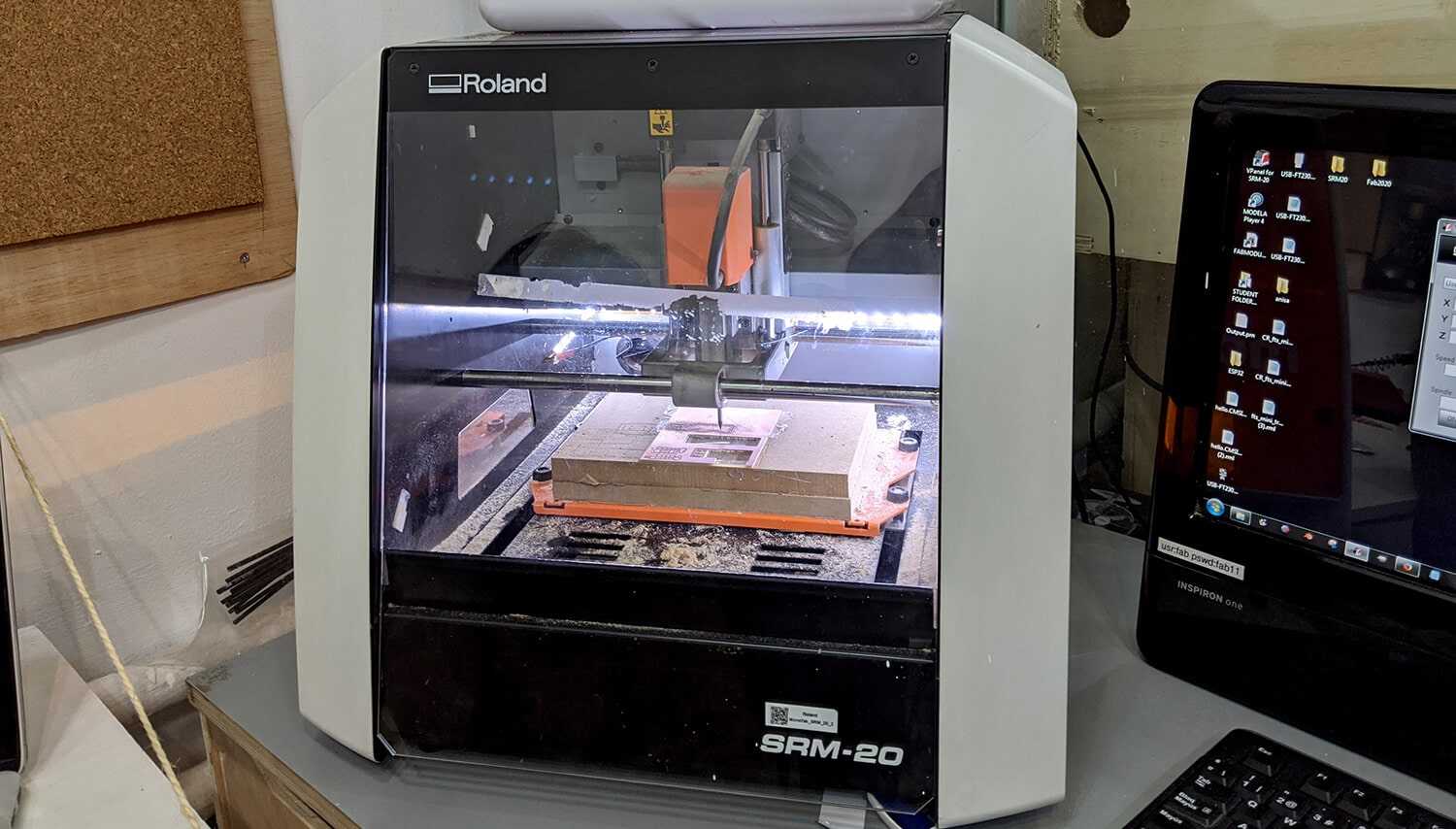
We used the Roland MonoFab SRM-20 machine to mill this test file provided by the instructors. Detailed specs of the machine:
- Work area: 203.2 x 152.4 x 60.5mm
- Loadable workpiece weight: 2kg
- Operating speed: 6mm/min - 1,800mm/min
- Spindle speed: 3,000 – 7,000rpm
- Input Format : RML-1
- Material: Modeling Wax, Chemical Wood, Foam, Acrylic, PCB
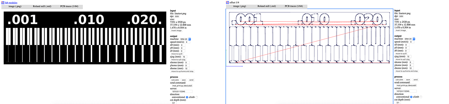
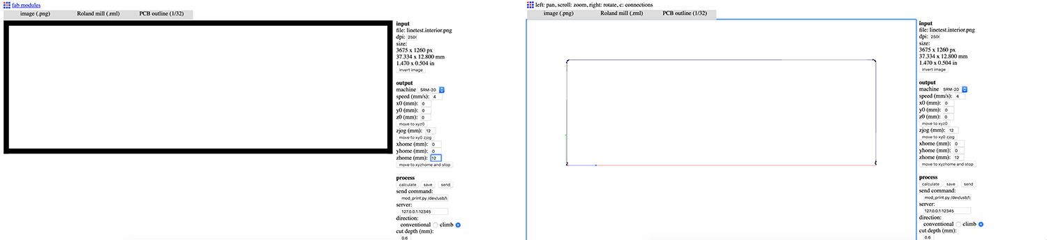
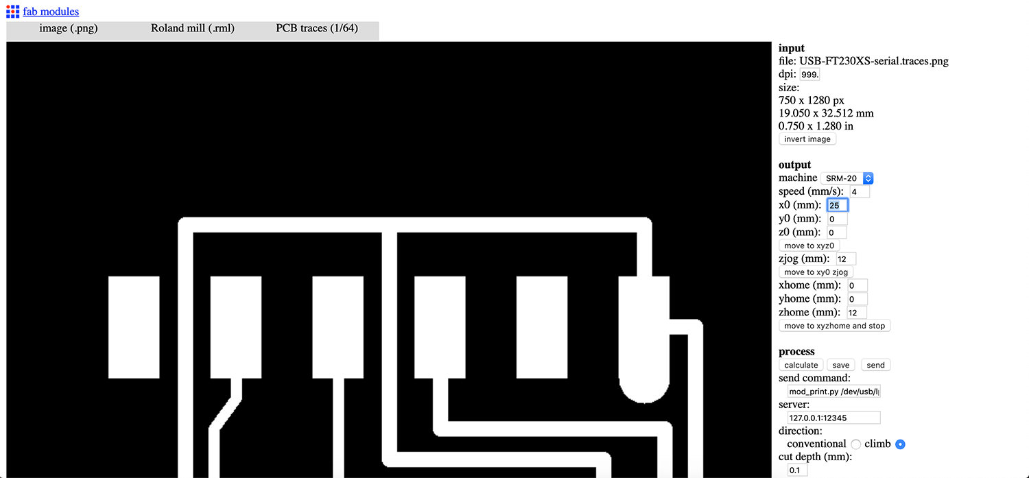
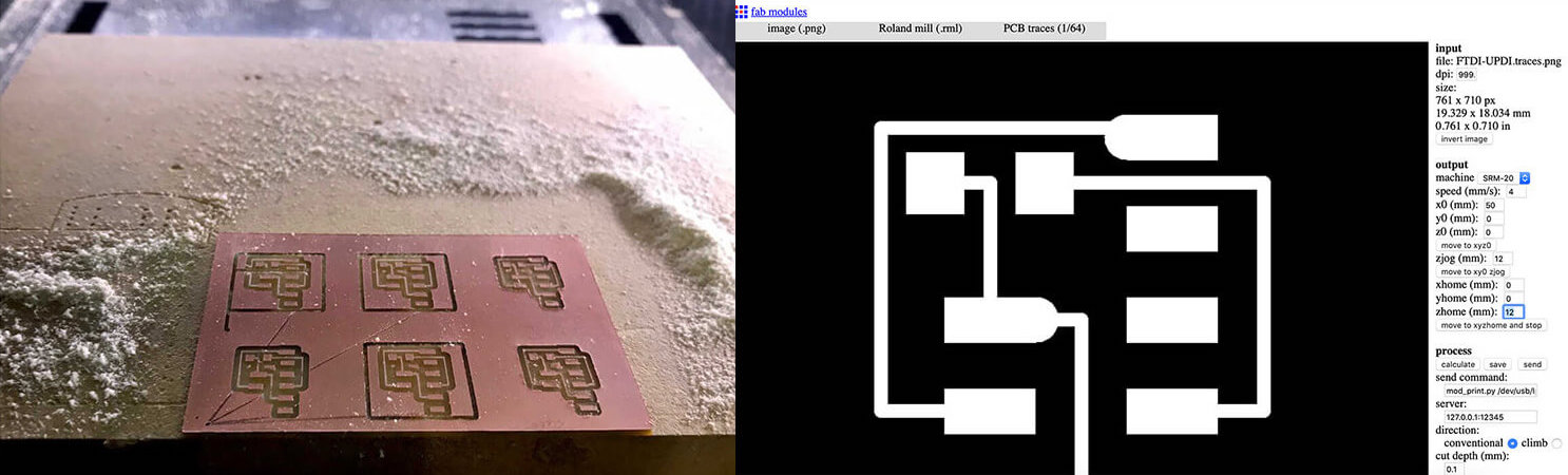
We prepared the .rml files using Fab Modules. The workflow of Fab Modules is pretty straightforward, and here are some recaps of steps followed:
- Select
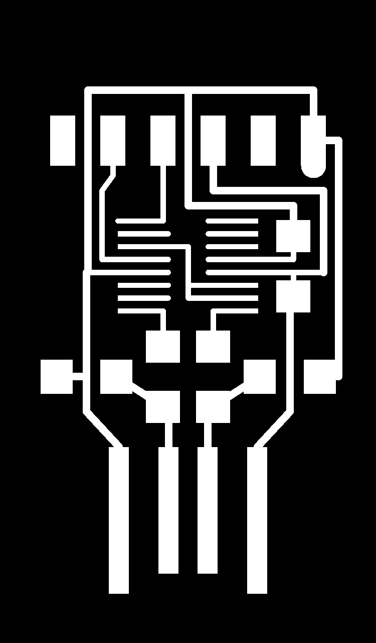
.pnginput format and load the.pngfile - Select
.rmloutput format - Select the proper process: PCB traces (1/64) or PCB outline (1/32). This will automatically define the proper cut depth (0.1mm for milling traces and 0.6mm for cutting).
- Select SRM-20 in the output machine. Modify settings to origin 0,0,0 (x,y,z); zjog=12mm (to make sure the milling bit will be lifted up while moving across the workpiece and avoid damaging both the traces and the fragile bit itself); and home 0,0,12 (x,y,z).
- Select the proper direction. The climb direction is the default one. More information of when to use which direction can be found here.
- Click the calculate button to calculate the toolpath and click the save button to save the
.rmlfile.
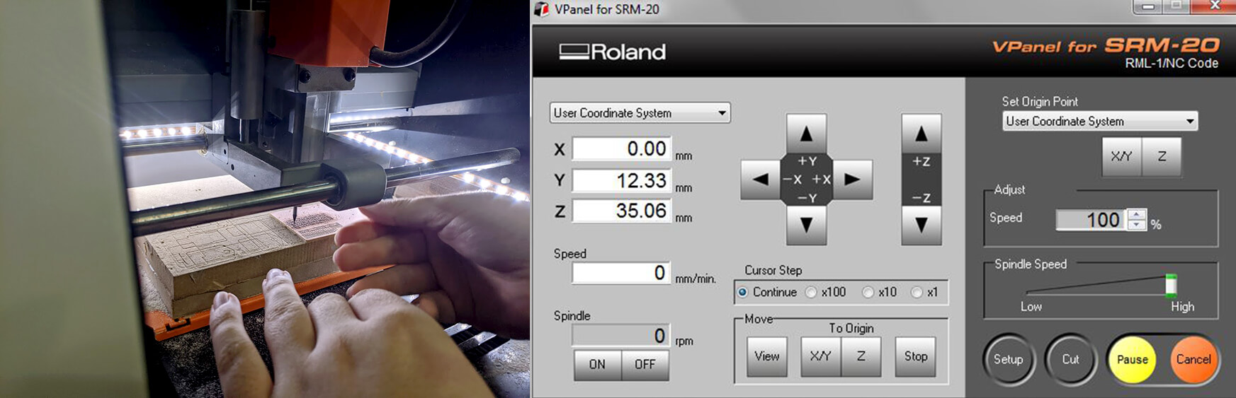
We used Roland VPanel controller to adjust the milling start point, the feed rate, and the spindle speed. Detailed summary of how to use the milling machine and VPanel:
- Choose the correct milling bit for the job. We were provided with 2 bits: the 1/64" used for milling the traces on the board and the 1/32" used for drilling holes and cutting.
- Insert the proper milling bit into the machine and manually adjust the Z origin.
- Set origin X/Y and Z in Vpanel. Click the Spindle button to test if the milling bit can cut through the copper layer.
- Click the Cut button, then add the
.rmlfile and start milling by clicking the Output button!
And here you go the result of the test:
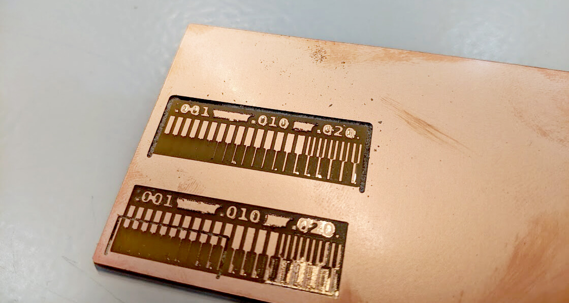
We had an issue with the outlines cutting. One side was not cut completely. We managed to generate the file multiple times and did the process again, but we still had the same problem. However, we could tell from the failed test that using the default settings of Fab Modules, the machine is able to mill up to 0.01mm thin trace.
What I personally learned
- Be careful while using the double-sided tape to fix the position of the workpiece. Any negligence can lead to a mess, especially when we are going to use leftovers.
- In order to pause the milling process immediately when something bad happens, always keep the speed a bit slow, around 50 - 60%. In the case of using leftovers, keep the speed around 20 - 30%.
- In order to check if the cut depth is enough, we should execute the Spindle option and make sure the color of the dust is a pinky combination of copper and resin.
- Always reset Z origin after changing the milling bits, and moving to Z origin should be done poco a poco.
- The machine will remove more material when we use
.rmlfiles generated with conventional direction selected. The climb option is recommended. - Last but not least, NEVER DROP THE MILLING BITS ONTO THE FLOOR! (I broke mine that way!)
Individual assignment - Mill and solder the FTDI SERIAL board and the UPDI adapter
In order to save time and materials, I teamed up with Roger Anguera, Antoine Jaunard, and Marco Cataffo because all of us were going to make the FTDI board & UPDI adapter. We did not expect that due to this we faced a lot of problems which perhaps we would not know of while milling a single board. I also learned how to mill multiple boards at the same time which is useful for my own Final Project.
mods vs. Fab Modules
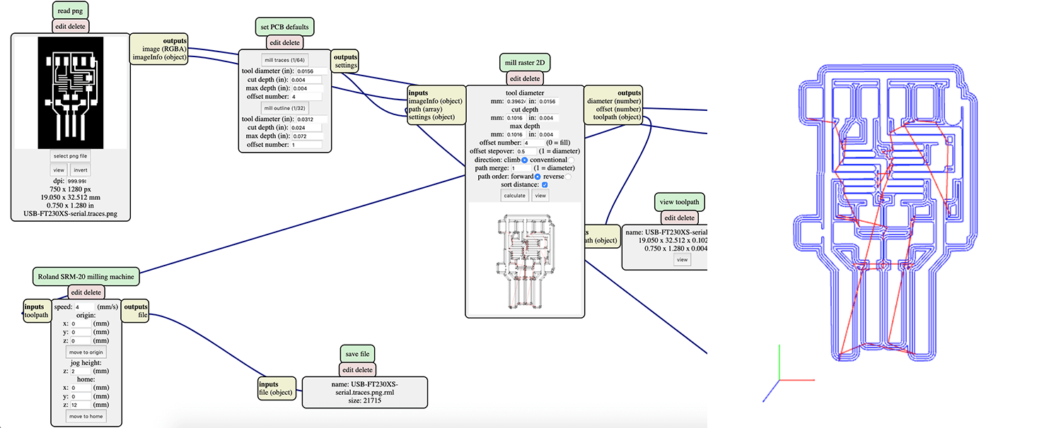
We tried to use mods to create our first .rml files for the traces of the FTDI SERIAL board. The workflow is a bit more complicated than Fab Modules, but is still digestible in general.
Some essential steps to follow:
- Right-click and select program > open server program
- Select the machine used to mill the PCB, in this case, Roland Mill SRM-20
- Select input format which is usually image
.png, drawing.svg, or mesh.stl. In this case, I chose.png. Now we can see a Grasshopper look-alike, which is not something I fancy. - Select the
.pngfile - Modify settings for Roland SRM-20 milling machine to origin 0,0,0 and home 0,0,12 (x,y,z). We also need to check the cut depth for both trace (1/64) and outline (1/32) milling processes in set PCB defaults module.
- Click the calculate button in mill raster 2D module to calculate the toolpath
- Delete the WebSocket module and add module > open server module > file > save module instead.
- Connect the output file of Roland SRM-20 milling machine module to the input of save file module. This will help us to be able to save the
.rmlfile.
After generating the first .rml file, I decided to go back to Fab Modules for its Tue-friendly UI. In order to mill 4 FTDI boards at the same time, we had to generate 4 files with 4 different origins: 0,0,0; 25,0,0; 0,35,0; and 25,35,0. For milling 4 UPDI adapters, we exported 4 files with 4 different origins: 0,0,0; 25,0,0; 0,25,0; and 25,25,0.
Milling the board
We used the same SRM-20 machine and followed the same above-mentioned steps to mill the 4 boards. Do I look like I was enjoying fixing the milling bit?
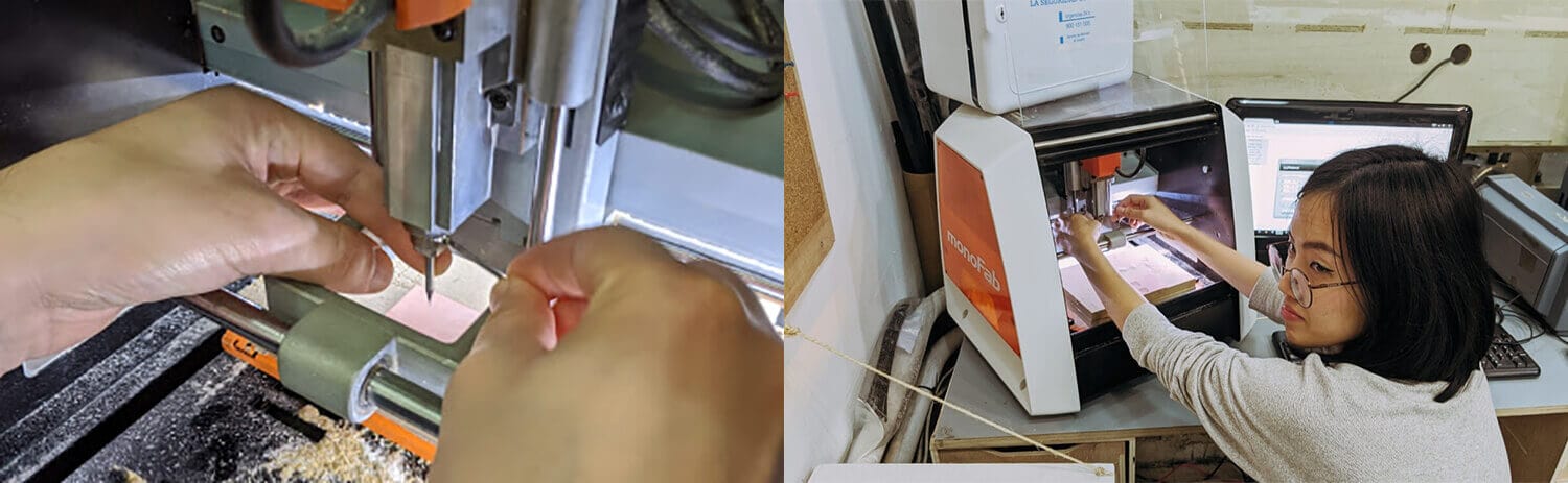
Below is a video recording the milling process:
The first time we milled the FTDI boards, the Z-axis wasn't defined correctly and some un-milled parts remained on the PCB after the process. The un-milled parts are a bit coppery shiny compared to the rest. We had to restart the process and mill the boards a little deeper.
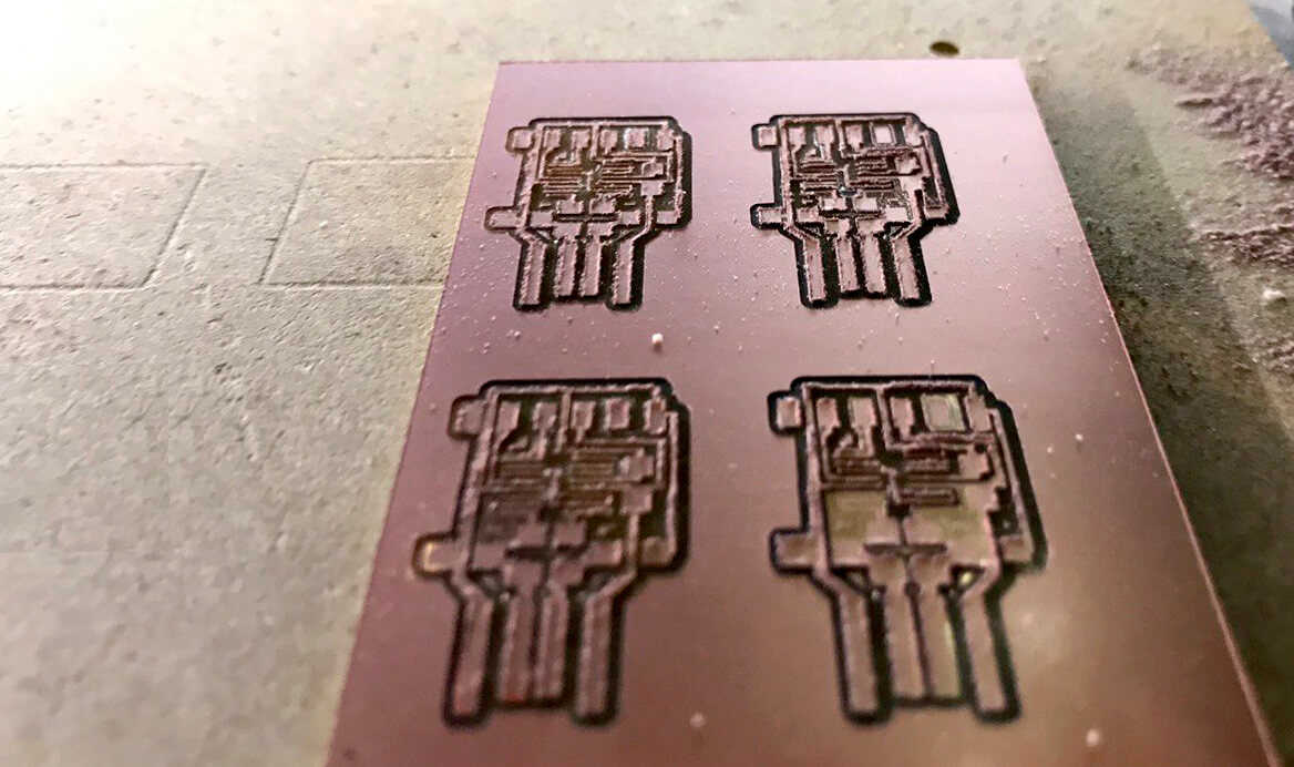
We then had a problem with the UPDI adapters. We forgot to set the z-axis of the home point to be greater than 0, and that's why it made a scratch across the milled parts. Since there were places left, we milled 2 more UPDIs with zhome=12mm and the new origins: 50,0,0 and 50,25,0.
Final pieces came out neat!
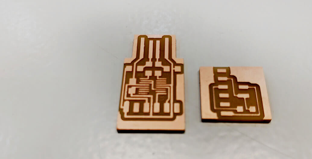
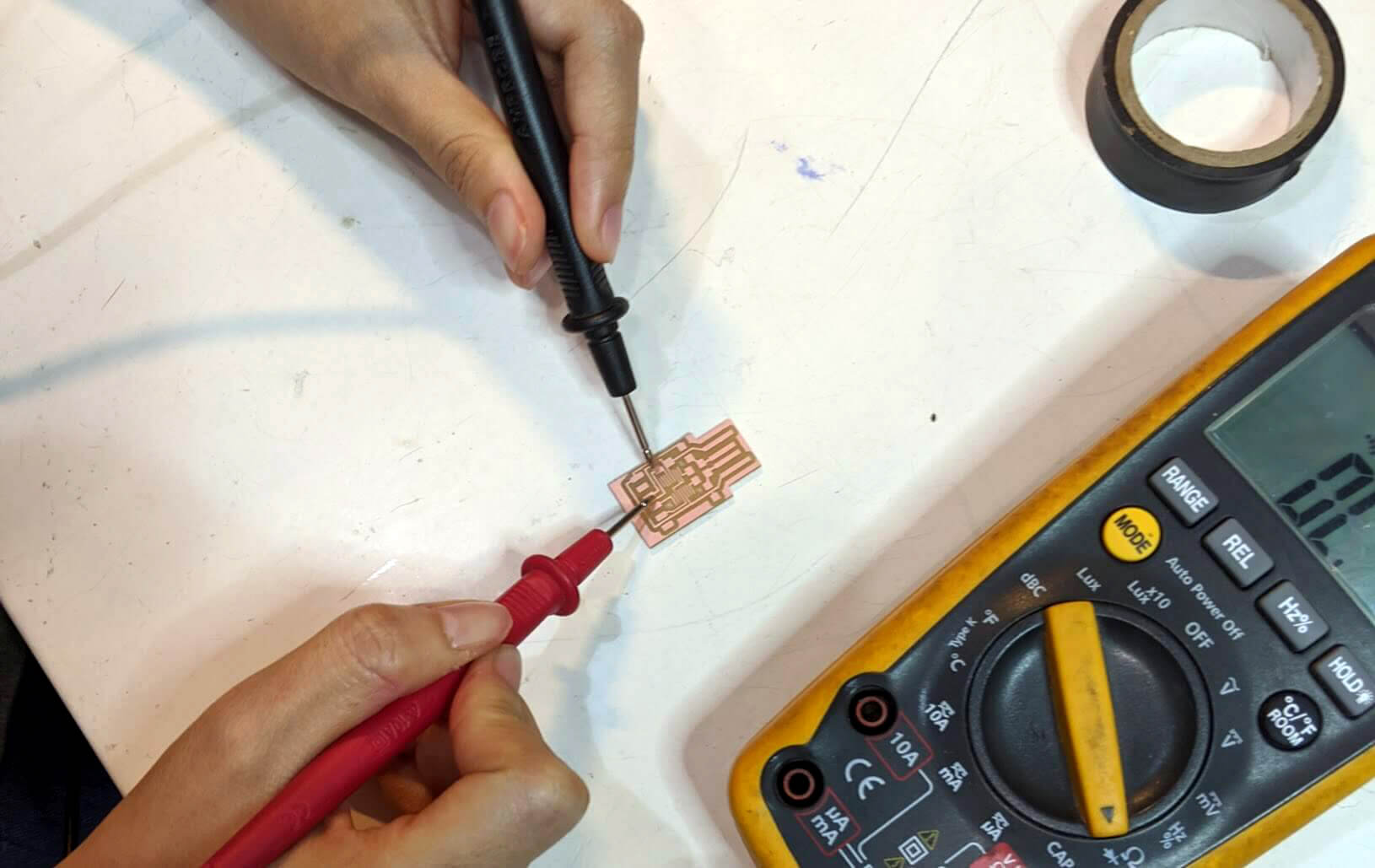
I used a multimeter to troubleshoot issues with my PCBs. A multimeter is a device used to measure electric current (amps), voltage (volts) and resistance (ohms). After ensuring the necessary connections, I moved forward to soldering the components.
Soldering components
Once I had the milled pieces all-good, I started the soldering process. I wrote down a shopping list of all required components and collected them from available components at the Fab Lab.
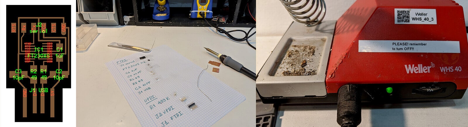
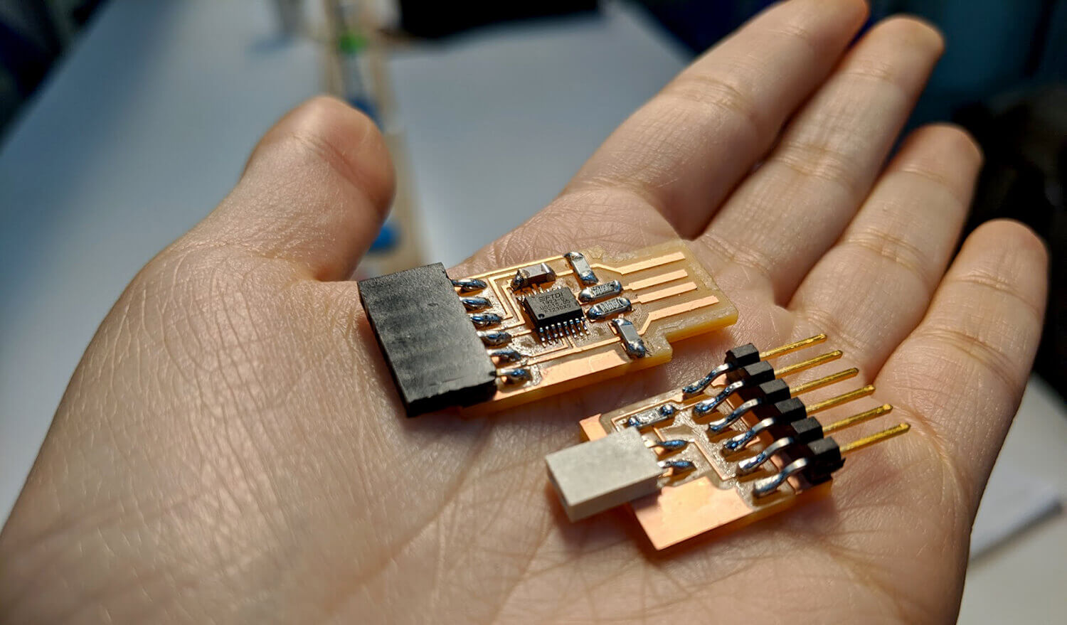
It took me plenty of time and patience to solder the components, especially the tiny IC. I even burned my hair while trying to see more clearly with my bare eyes, since the LED light equipped loupe gave me headaches. Then our instructor Rutvij Pathak said one magic phrase that saved my life: "Solder like you're painting with watercolor!" And here you go the pretty, shiny, and conductive (after testing with the multimeter) result:
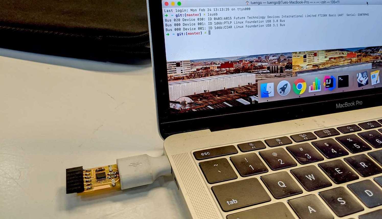
I tested the board with Santi's computer, and it was detected!
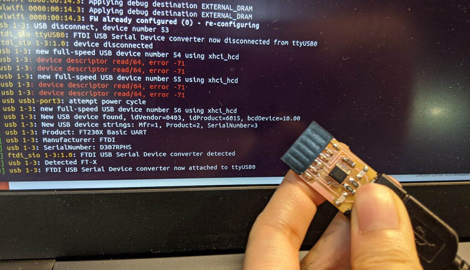
However, when I tried to test it with other computers, it couldn't be detected. After checking whether all connections were in beep-beep mode once again as Oscar suggested, I put more solder to one of the resistors, and finally, the board was detected on my Macbook!
Things I learned during the soldering process:
- Be careful of the soldering order. Make sure it's easy to access all components inside out, and none of them will be over-heated.
- To have easier access to the components, I used double-sided tape to fix the board to the table.
- Make sure the components are soldered completely to the board and all the welds are shiny. "Solder like you're painting with watercolor!"
- Always test whether there is an open circuit with the multimeter.
Additional delivery - Vinyl-cut the SWD adapter
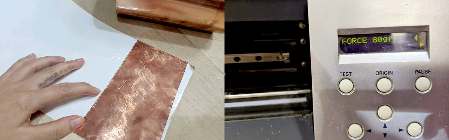
After finishing the minimum requirements of this week, I tried to explore another PCB manufacturing process which is vinyl-cutting the board using copper vinyl sheet. For this extra ball, I chose to cut the SWD adapter. Josep guided me through the process since he had experiences cutting the copper vinyl before.
The steps followed were quite similar to what I did last week with the Roland CAMM-1 Servo GX-24 machine. The only difference was that I had to stick the copper vinyl on top of a plastic sheet, and modify the Force settings to be a bit lower, around 80 gf.
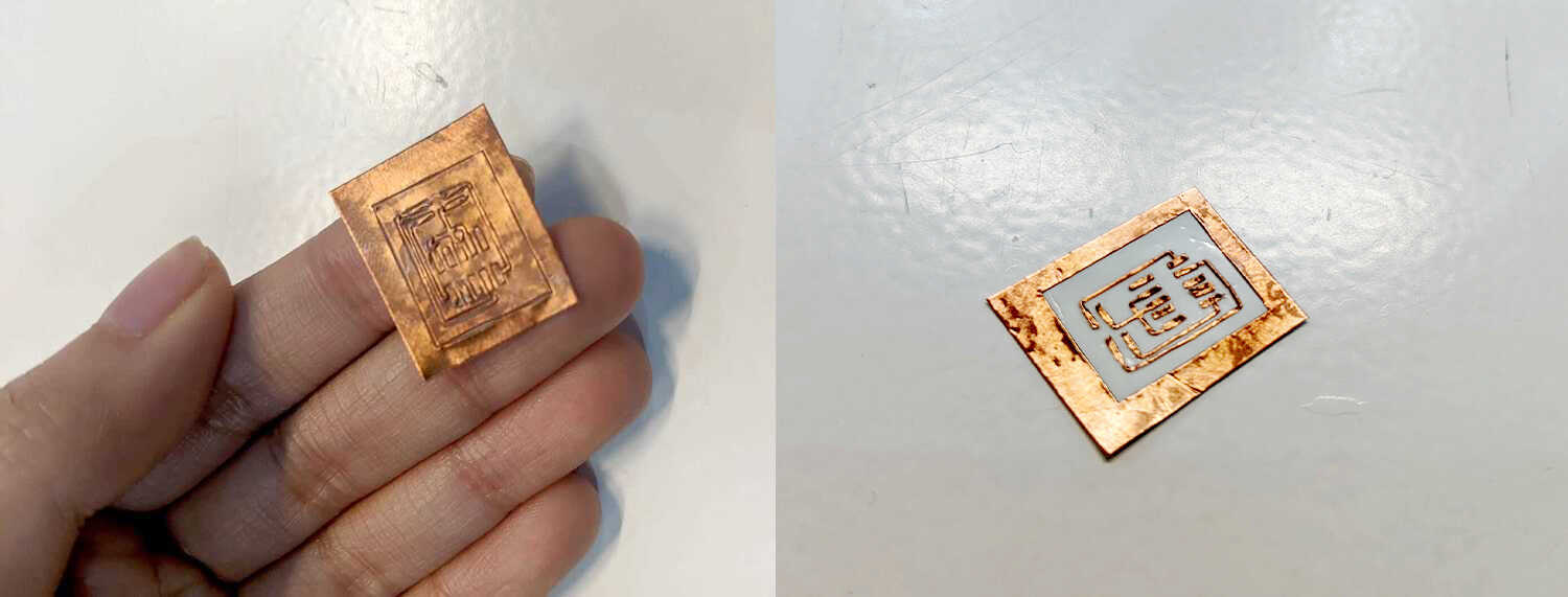
The trickiest part of this was peeling out the parts that I didn't want from a tiny board (those are the parts usually removed in the milling process). The copper vinyl might be thin, but not flexible. A good tip here was to use 2 tweezers at the same time, 1 tweezer to peel and the other to fix the positions of the parts I want to keep. After struggling for a while, I got my pretty cut board which I was quite happy with:
I decided not to proceed with the soldering process since I realized soldering over those not-so-clingy traces can be a real pain. I might want to try it out if I had some extra hands, and if so, I would solder as if I were performing an Ayurvedic massage.
Conclusion
It was a useful week since electronics was one of the most important skills that I would like to acquire during the Fab Academy. This week is all about showing our capabilities of making the PCB, but I feel more confident to explore further the designing and programming process.