W11 - Output Devices
1. Weekly Assignments ( -> what I did this week )
-
Group assignment
-
Measure the power consumption of an output device
- Document your work (in a group or individually)
( -> I measured the power consumption of servo motor ( SG90-HV ). )
-
Individual assignment
-
Add an output device to a microcontroller board you’ve designed and program it to do something
( -> I added a servo motor ( SG90-HV ) to the class kit with ATtiny44, and programed to control the rotational speed of servo. Also, I made ESP32 - based MCU, modifying “Barduino 2.0”, milling PCB, and tested it as a part of my Final Project Drive Simulator. )
Have you?
Questions from “Fab Academy 2020 Assignments and Assessment 
( -> my answers )
-
Linked to the group assignment page ( -> yes )
-
Documented how you determined power consumption of an output device with your group ( -> yes )
-
Documented what you learned from interfacing output device(s) to microcontroller and controlling the device(s) ( -> yes )
-
Described your design and fabrication process or linked to previous examples. ( -> yes )
-
Explained the programming process/es you used ( -> yes )
-
Outlined problems and how you fixed them ( -> yes )
-
Included original design files and code ( -> yes )
-
Included a ‘hero shot/video’ of your board ( -> yes )
2. Group Assignment Link
3. Works, steps and some details
3 - A . Online local session, ( ATTiny breakout board + breadboard + servo motor )
servo motors
SG90 ; lever-type, limited angle
SG90-HV ; continuous rotation
| board | software | input | output | |
|---|---|---|---|---|
| 1 | Arduino | Arduino | potentiometer | SG90-HV |
| 2 | Arduino | Arduino | potentiometer | SG90 |
| 3 | ATtiny44 (breadboard) | Arduino | potentiometer | SG90-HV |
| 4 | ATtiny44 (breadboard) | Arduino | potentiometer | SG90 |
| 5 | ATtiny44 (breadboard) | C | none | SG90-HV |
| 6 | ATtiny44 (breadboard) | C | none | SG90 |
0) preparation
- soldering ( ATTiny44 breakout board )
( I missed the XTAL soldering because my solder was too hot maybe. So, I used internal 8MHz clock instead of external 20MHz.)
- draw the cirquit diagram in accoradnce with the sample shown in the fab academy site ( servo )
- connecting the components of the breadboard
1) test 1
| board | software | input | output | |
|---|---|---|---|---|
| 1 | Arduino | Arduino | potentiometer | SG90-HV |
code ” servo_sg90hv_test_arduino.ino “
#include <Servo.h>

Servo servo;//create servo objects

void setup(){
  //servo signal to GPTO pin3
  servo.attach(3);
  Serial.begin(9600);

}

void loop(){
  //read sensor value
  int val=analogRead(0);
  //Serial.println(val);
  Serial.print(val);
  Serial.println("");
  delay(100);
  //map() to convert sensor value(0-678) to angle(0-180)
  int angle=map(val,0,678,0,180);
  //output to servo
 // Serial.println(angle);
  servo.write(angle);

}
2) test 2
| board | software | input | output | |
|---|---|---|---|---|
| 2 | Arduino | Arduino | potentiometer | SG90 |
code ” servo_sg90hv_test_arduino.ino ” <- same as test 1
3) test 3
| board | software | input | output | |
|---|---|---|---|---|
| 3 | ATtiny44 (breadboard) | Arduino | potentiometer | SG90-HV |
In Arduino IDE, I selected clock ; “8 MHz (internal) ” from “Tool” option.
code ” servo_sg90hv_attiny44.ino “
#include <Servo.h>

Servo servo;//create servo objects

void setup(){
  //servo signal to GPTO pin7
  servo.attach(7);
  Serial.begin(9600);

}

void loop(){
  //read sensor value
  int val=analogRead(0);
  //Serial.println(val);
  Serial.print(val);
  Serial.println("");
  delay(100);
  //map() to convert sensor value to speed
  int angle=map(val,50,400,56,84);
  //output to servo
 // Serial.println(angle);
  servo.write(angle);

}
I carefully tuned the parameters in the “map” function so that servo rotational speed can be controlled smoothly. ( for example, the numbers ; 56, 84 )
4) test 4
| board | software | input | output | |
|---|---|---|---|---|
| 4 | ATtiny44 (breadboard) | Arduino | potentiometer | SG90 |
In Arduino IDE, I selected clock ; “8 MHz (internal) ” from “Tool” option.
code ” servo_sg90hv_attiny44.ino ” <- same as test 3
result ; moves, but not smooth
no video
5) test 5
| board | software | input | output | |
|---|---|---|---|---|
| 5 | ATtiny44 (breadboard) | C | none | SG90-HV |
Firstly, I used “hello.servo.44.c.make” and “hello.servo.44.c”, but it didn’t work, because of the clock frequency difference.
In accordance with the suggestion from the instructor ( Kae Nagano ), some numbers in the codes “hello.servo.44.c.make” and “hello.servo.44.c” were changed.
code ” 8mh_hello.servo.44.c.make ”
changed portions ;
- line number 1 ; file name
- line number 4 ; F_CPU = 8000000 ( original, F_CPU = 20000000 )
PROJECT=8mh_hello.servo.44
SOURCES=$(PROJECT).c
MMCU=attiny44
F_CPU = 8000000

CFLAGS=-mmcu=$(MMCU) -Wall -Os -DF_CPU=$(F_CPU)

$(PROJECT).hex: $(PROJECT).out
    avr-objcopy -O ihex $(PROJECT).out $(PROJECT).c.hex;\
    avr-size --mcu=$(MMCU) --format=avr $(PROJECT).out

$(PROJECT).out: $(SOURCES)
    avr-gcc $(CFLAGS) -I./ -o $(PROJECT).out $(SOURCES)

program-bsd: $(PROJECT).hex
    avrdude -p t44 -c bsd -U flash:w:$(PROJECT).c.hex

program-dasa: $(PROJECT).hex
    avrdude -p t44 -P /dev/ttyUSB0 -c dasa -U flash:w:$(PROJECT).c.hex

program-avrisp2: $(PROJECT).hex
    avrdude -p t44 -P usb -c avrisp2 -U flash:w:$(PROJECT).c.hex

program-avrisp2-fuses: $(PROJECT).hex
    avrdude -p t44 -P usb -c avrisp2 -U lfuse:w:0x5E:m

program-usbtiny: $(PROJECT).hex
    avrdude -p t44 -P usb -c usbtiny -U flash:w:$(PROJECT).c.hex

program-usbtiny-fuses: $(PROJECT).hex
    avrdude -p t44 -P usb -c usbtiny -U lfuse:w:0x5E:m

program-dragon: $(PROJECT).hex
    avrdude -p t44 -P usb -c dragon_isp -U flash:w:$(PROJECT).c.hex

program-dragon-fuses: $(PROJECT).hex
    avrdude -p t44 -P usb -c dragon_isp -U lfuse:w:0x5E:m

program-ice: $(PROJECT).hex
    avrdude -p t44 -P usb -c atmelice_isp -U flash:w:$(PROJECT).c.hex

program-ice-fuses: $(PROJECT).hex
    avrdude -p t44 -P usb -c atmelice_isp -U lfuse:w:0x5E:m
code ” 8mh_hello.servo.44.c ”
changed portions ; ( basically, 8MHz/20MHz = 2/5 )
-
line number 46 ; ICR1 = 10000; ( original, ICR1 = 25000; )
-
line number 59 ; OCR1A = 700; ( original, 1250, tuned from 500 (=1250X2/5) )
-
line number 64 ; OCR1A = 777; ( original, 1875, tuned from 750 (=1875X2/5) )
-
line number 69 ; OCR1A = 900; ( original, 2500, tuned from 1000 (=2500X2/5) )
according to the test results, in the range of 500 to 720
OCR1A ; 500 -> 720 CW ( clockwise ) fast -> slow, respectively
OCR1A ; 730 -> 770 stop
OCR1A ; 775 -> 1000 CCW ( counter clockwise ) slow -> fast, respectively
//
// hello.servo.44.c
//
// servo motor hello-world
//
// set lfuse to 0x5E for 20 MHz xtal
//
// Neil Gershenfeld
// 4/8/12
//
// (c) Massachusetts Institute of Technology 2012
// This work may be reproduced, modified, distributed,
// performed, and displayed for any purpose. Copyright is
// retained and must be preserved. The work is provided
// as is; no warranty is provided, and users accept all
// liability.
//

#include <avr/io.h>
#include <util/delay.h>

#define output(directions,pin) (directions |= pin) // set port direction for output
#define set(port,pin) (port |= pin) // set port pin
#define clear(port,pin) (port &= (~pin)) // clear port pin
#define pin_test(pins,pin) (pins & pin) // test for port pin
#define bit_test(byte,bit) (byte & (1 << bit)) // test for bit set
#define position_delay() _delay_ms(1000)

#define PWM_port PORTA
#define PWM_pin (1 << PA6)
#define PWM_direction DDRA

int main(void) {
   //
   // main
   //
   // set clock divider to /1
   //
   CLKPR = (1 << CLKPCE);
   CLKPR = (0 << CLKPS3) | (0 << CLKPS2) | (0 << CLKPS1) | (0 << CLKPS0);
   //
   // set up timer 1
   //
   TCCR1A = (1 << COM1A1) | (0 << COM1A0); // clear OC1A on compare match
   TCCR1B = (0 << CS12) | (1 << CS11) | (0 << CS10) | (1 << WGM13); // prescaler /8, phase and frequency correct PWM, ICR1 TOP
   ICR1 = 10000; // 20 ms frequency
   //
   // set PWM pin to output
   //
   clear(PWM_port, PWM_pin);
   output(PWM_direction, PWM_pin);
   //
   // main loop
   //
   while (1) {
      //
      // 1 ms PWM on time
      //
      OCR1A = 700;
      position_delay();
      //
      // 1.5 ms PWM on time
      //
      OCR1A = 777;
      position_delay();
      //
      // 2 ms PWM on time
      //
      OCR1A = 900;
      position_delay();
      }
   }
make -f 8mh_hello.servo.44.c.make
make -f 8mh_hello.servo.44.c.make program-usbtiny
6) test 6
| board | software | input | output | |
|---|---|---|---|---|
| 6 | ATtiny44 (breadboard) | C | none | SG90 |
result ; moves, but not smooth
no video
3 - B . Making PCB ( ESP32 + servo motor ) for Final Project ( Drive simulator ) , ( on 2020/07/05 )
For the Drive Simulator of my Final Project, which would utilize 3 servo motors (SG90), I decided to make ESP32-based MCU, so that it can communicate with other devices like iPhone via wifi or BLE.
output 1 ; servo motor for rolled paper control ( SG90-HV (continuous rotation))
output 2 ; servo motor for magnet control ( SG90-HV (continuous rotation))
output 3 ; servo motor for slope control ( SG90 (lever-motion))
output 4 ; SSR (Solid State Relay) control to ON/OFF the generator coil
input 1 ; generator speed in terms of voltage from 1 coil (out of 8 coils)
input 2 ; slope signal from photo reflector on the drive simulator
input 3 (BLYNK BLE) ; X-Y of JOYSTICK module to control the above output 1 and 2
input 4, 5, 6 ; potentiometers for trouble shooting ( substitution of the above input 1, 2, 3, if needed)
Component layout
Considering the switch accessibility on the Drive Simulator, I planned to move the slider switch to the side of FTDI connector, which is the modification point from “Barduino 2.0”
“Barduino, fablab Kamakura” link
| Slider switch was relocated. | |
|---|---|
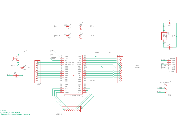 |
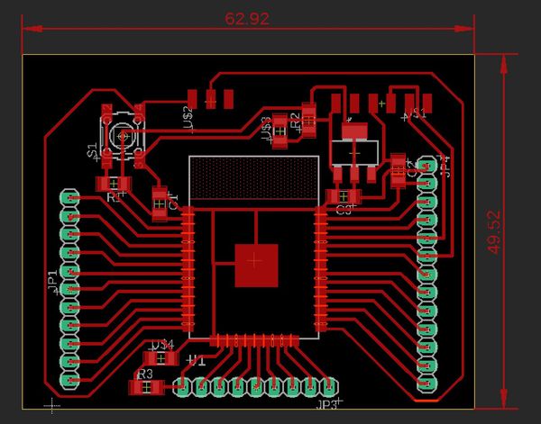 |
This time, I tried “ground plane” referring the fablab Kamakura site shown below.
“How to make ground plane in Eagle”
summary of the procedures are ,,,,
surround the area to be ground plane, using “polygon” ( broken line appears )
name it to “GND”
“ratnest” it, then ground plane appears (red-colored area)
| ratnest | ground plane |
|---|---|
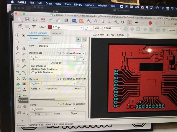 |
 |
| trace (.png file can be downloaded from the bottom of this page) | |
|---|---|
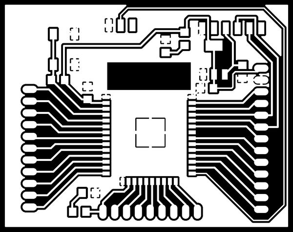 |
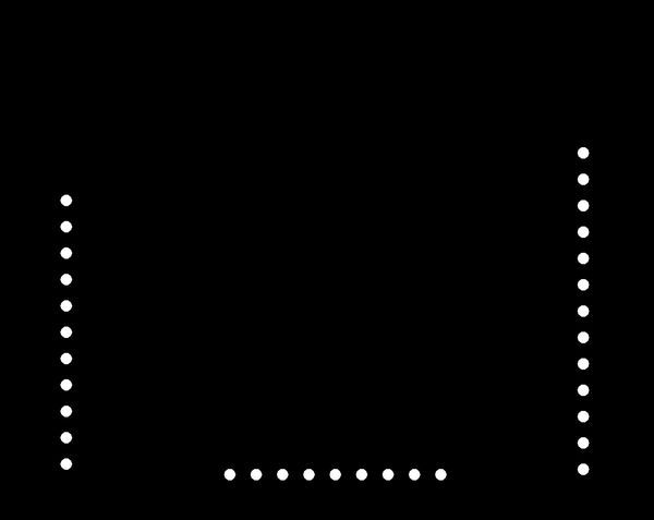
| outcut (.png file can be downloaded from the bottom of this page) | holes (.png file can be downloaded from the bottom of this page) |
|---|---|
 |
 |
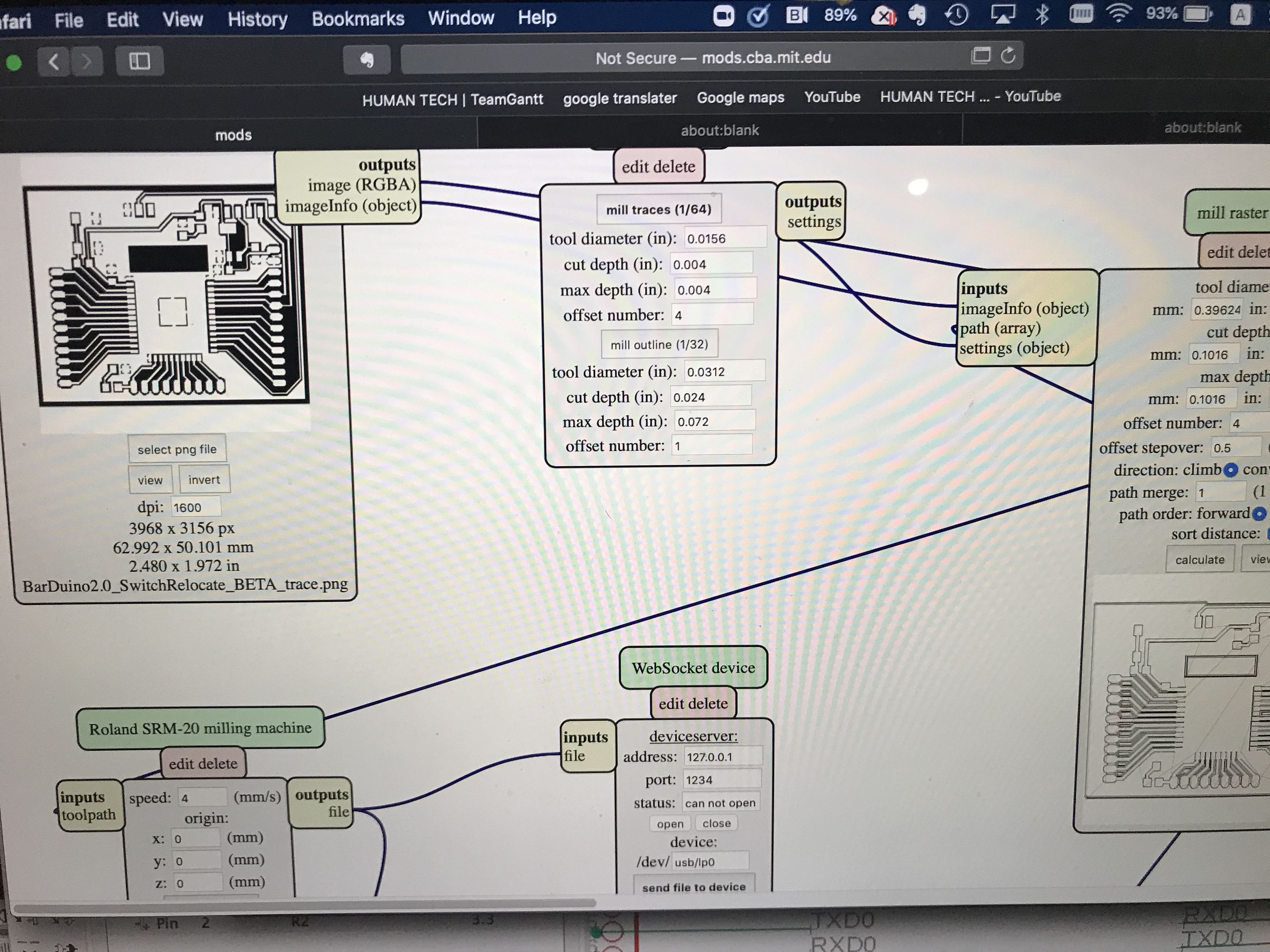
MODs to create “.rml” files.
CNC parmeters for circuit pattern
tool diameter (in) ; 0.0156 (1/64)
cut depth (in) ; 0.004
max depth (in) ; 0.004
offset number ; 4
milling speed ; 4 mm/s
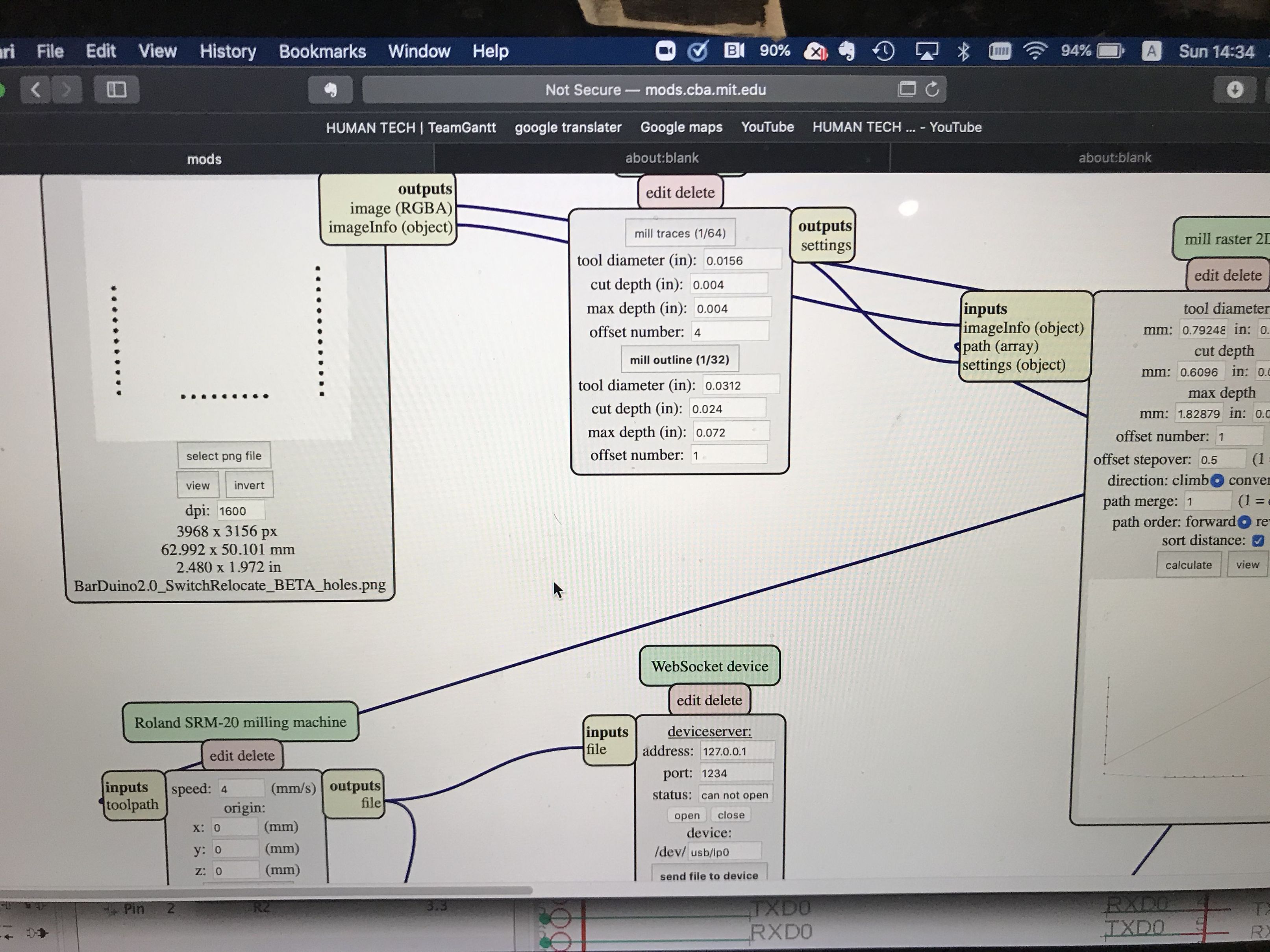
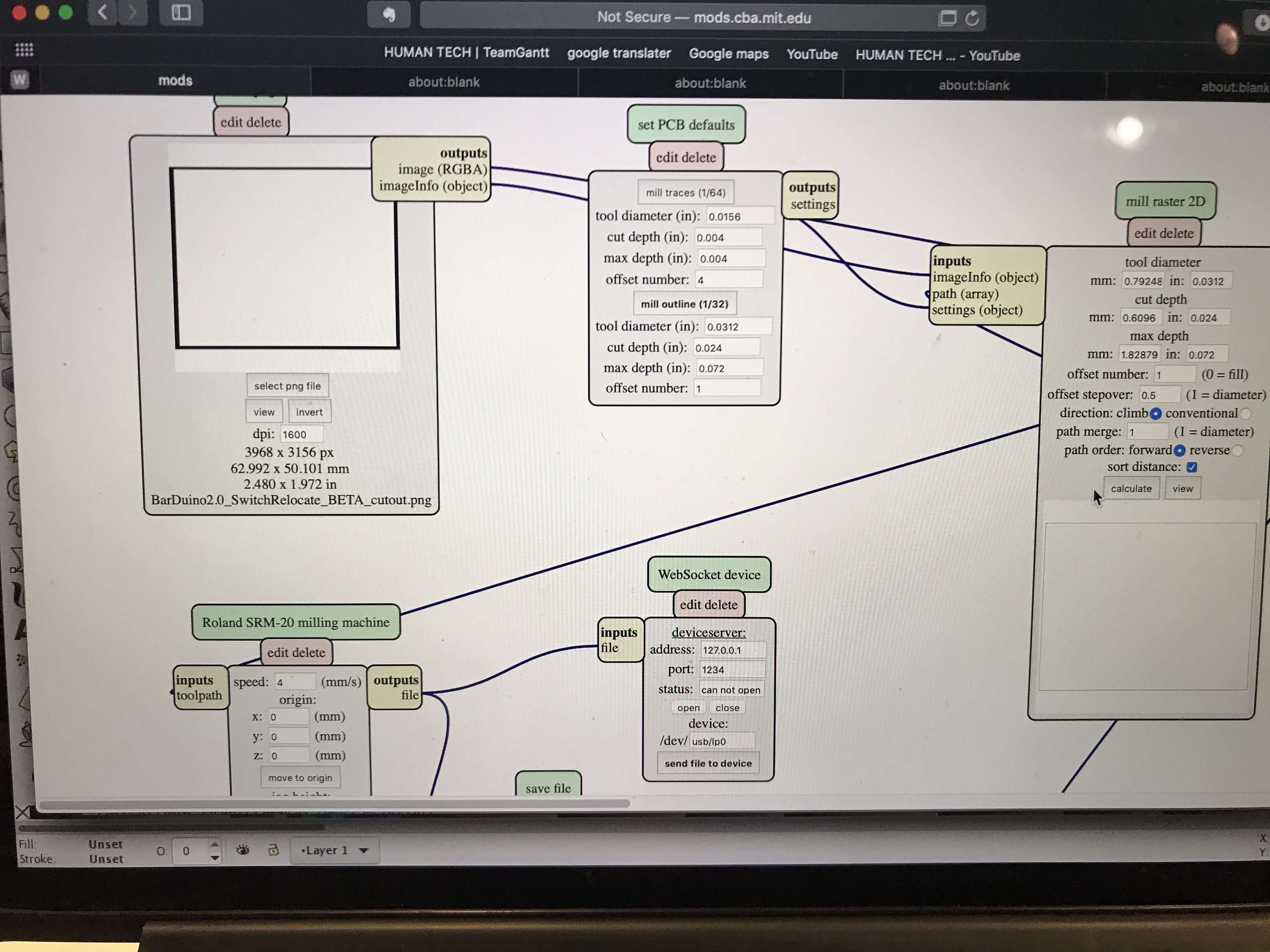
CNC parmeters for holes and outline
tool diameter (in) ; 0.0312 (1/32)
cut depth (in) ; 0.024
max depth (in) ; 0.072
offset number ; 1
milling speed ; 4 mm/s
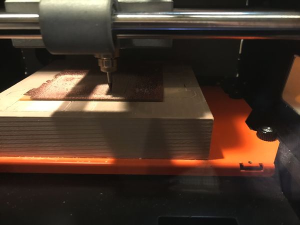
milling on SRM20
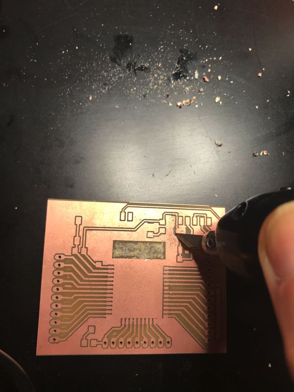
Some portions were not milled properly, I cut them using ultra-sonic cutter ( and hand files).
 |
 |
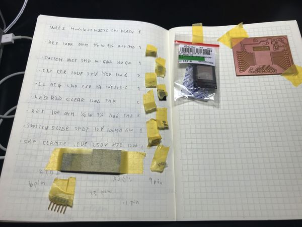
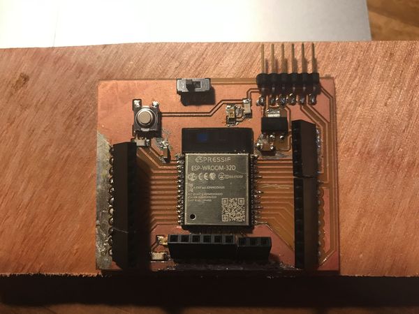
| stuffing | |
|---|---|
 |
 |
| put some pin number labels | |
|---|---|
 |
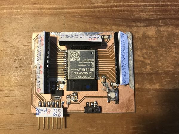 |
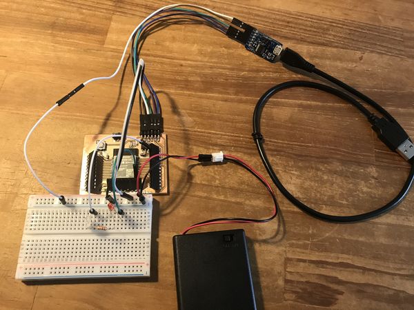
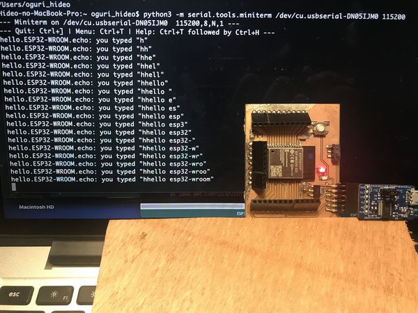
Functionality check in accordance with the site below.
And, the results were no problem.
“Barduino, fablab Kamakura” link
| LED blink | hello echo |
|---|---|
 |
 |
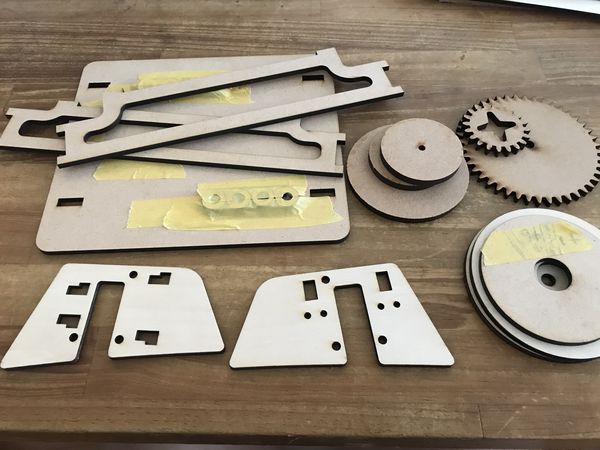
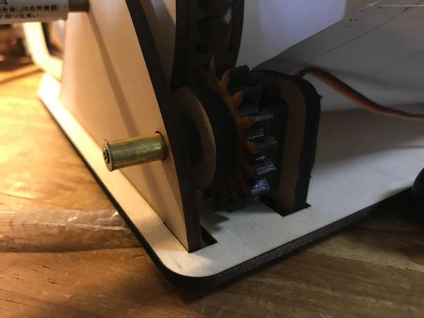
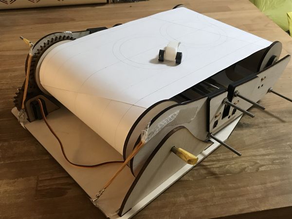
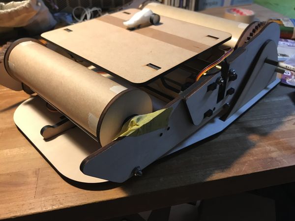
Assembling the drive simulator
| laser cutting parts | put rubber sheet on servo motor, for noise reduction |
|---|---|
 |
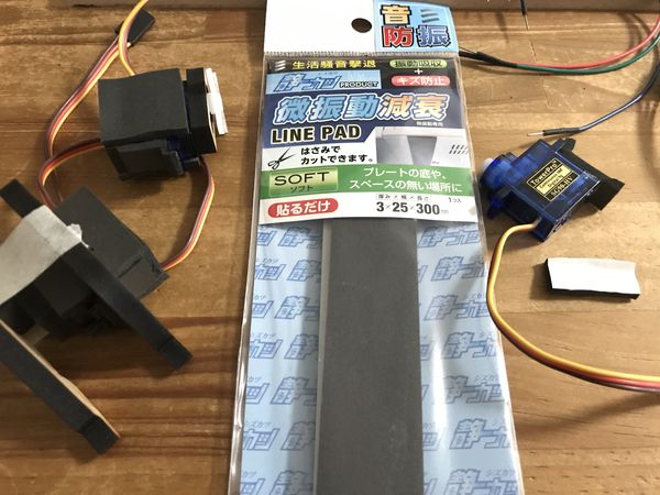 |
| output 2 ; servo motor for magnet control ( SG90-HG (continuous rotation)) | |
|---|---|
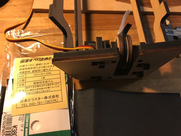 |
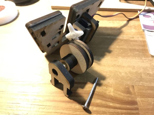 |
| output 3 ; servo motor for slope control ( SG90 (lever-motion)) ( in the back of this photo ) |
output 1 ; servo motor for rolled paper control ( SG90-HG (continuous rotation)) |
|---|---|
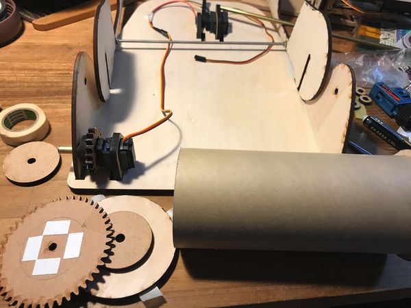 |
 |
 |
 |
programing
( I referred some BLYNK example files in Arduino IDE. )
Regarding the setting of “Blynk BLE” on Arduino IDE and Blynk APP ( iPhone ), please refer ” 12. Interface and Application Programming , Group assignment Page “
“ESP32_Blynk_BLE_DriveSim_servo.ino”
#define BLYNK_PRINT Serial

#define BLYNK_USE_DIRECT_CONNECT

#include <BlynkSimpleEsp32_BLE.h>
#include <BLEDevice.h>
#include <BLEServer.h>


#include <ESP32Servo.h>

// You should get Auth Token in the Blynk App.
// Go to the Project Settings (nut icon).
char auth[] = "Your Auth Token";

// create three servo objects
Servo servo1;
Servo servo2;
Servo servo3;

BLYNK_WRITE(V1)
{
  servo1.write(param.asInt());
}

BLYNK_WRITE(V2)
{
  servo2.write(param.asInt());
}

BLYNK_WRITE(V3)
{
  servo3.write(param.asInt());
}


void setup() {

  {
    // Debug console
    Serial.begin(9600);
    Serial.println("Waiting for connections...");

    Blynk.setDeviceName("Blynk");

    Blynk.begin(auth);

    servo1.attach(4);
    servo2.attach(12);
    servo3.attach(14);

  }


}

void loop()

{
  Blynk.run();
}
Then, I did set the MCU and battery ( “eneloop” Ni-MH, rechargeable ), tested the “drivability ” from my iPhone. It worked fine.
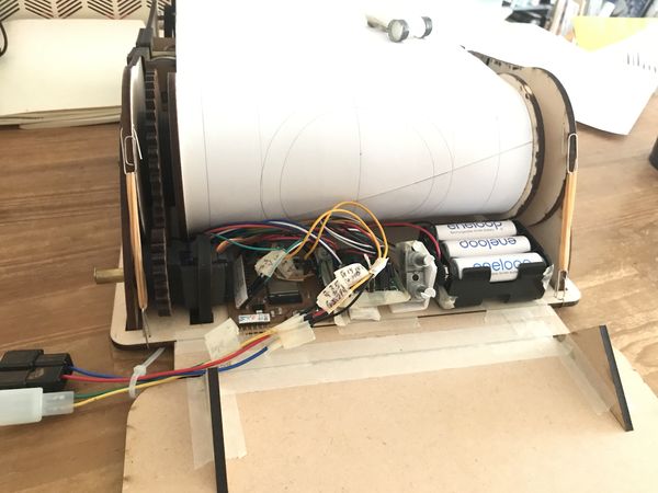 |
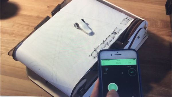 |
( During this test, I controlled “output3, slope ” from BLYNK using the “v3” parameter in the program. )
4. Important Learning Outcome
1) basic speed control of servo motor
2) PWM setting and MC clock selection ( but need to explore PWM control more deeply )
3) making the ground plane in EAGLE CAD, and PCB milling technic
4) using BLYNK BLE to control the servo motors
5. Links to Files and Code
servo_sg90hv_test_arduino.ino download
servo_sg90hv_attiny44.ino download
8mh_hello.servo.44.c download
8mh_hello.servo.44.c.make download
“BarDuino2.0_SwitchRelocate_BETA.sch”
“BarDuino2.0_SwitchRelocate_BETA.brd”
“BarDuino2.0_SwitchRelocate_BETA_trace.png”
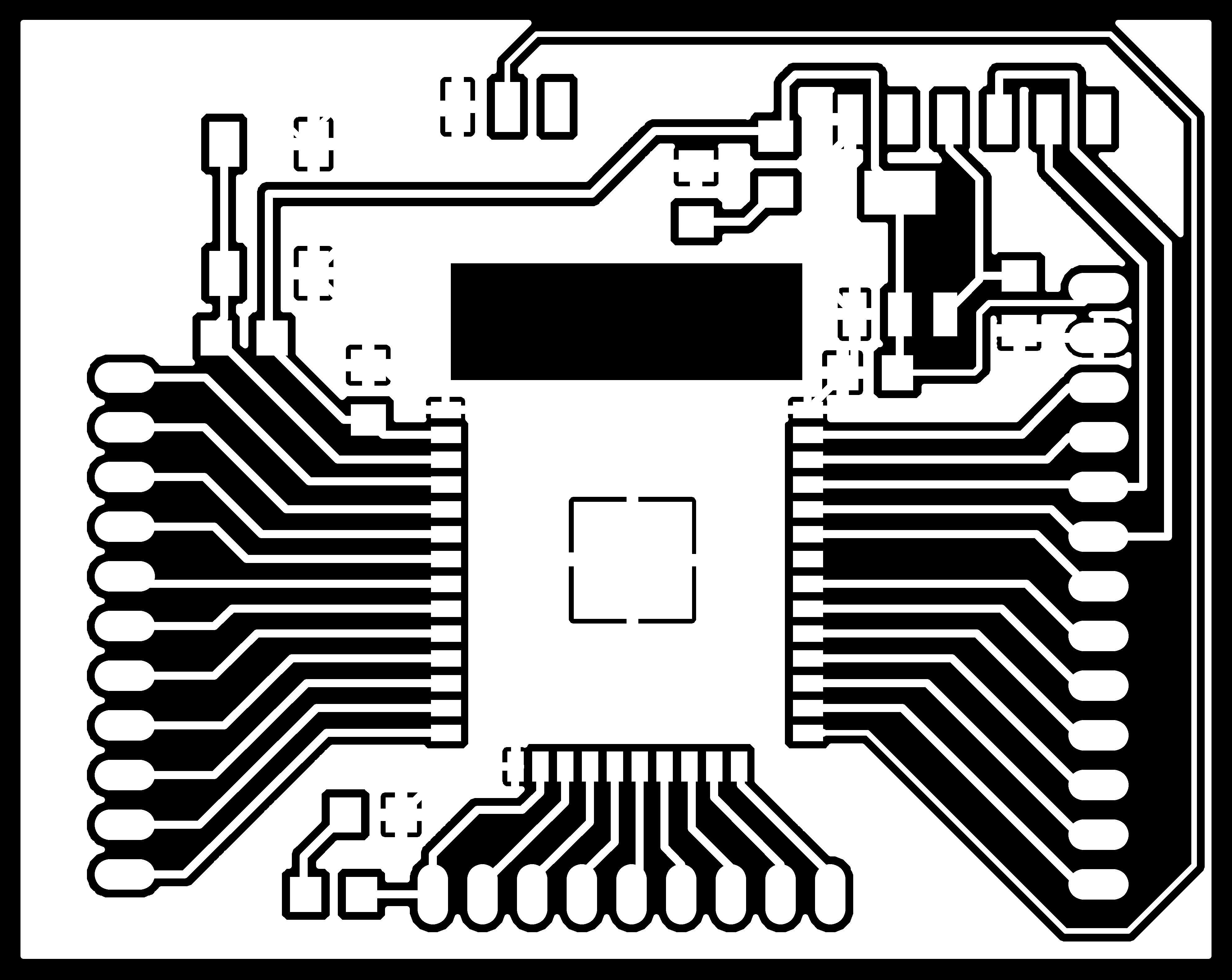
“BarDuino2.0_SwitchRelocate_BETA_holes.png”
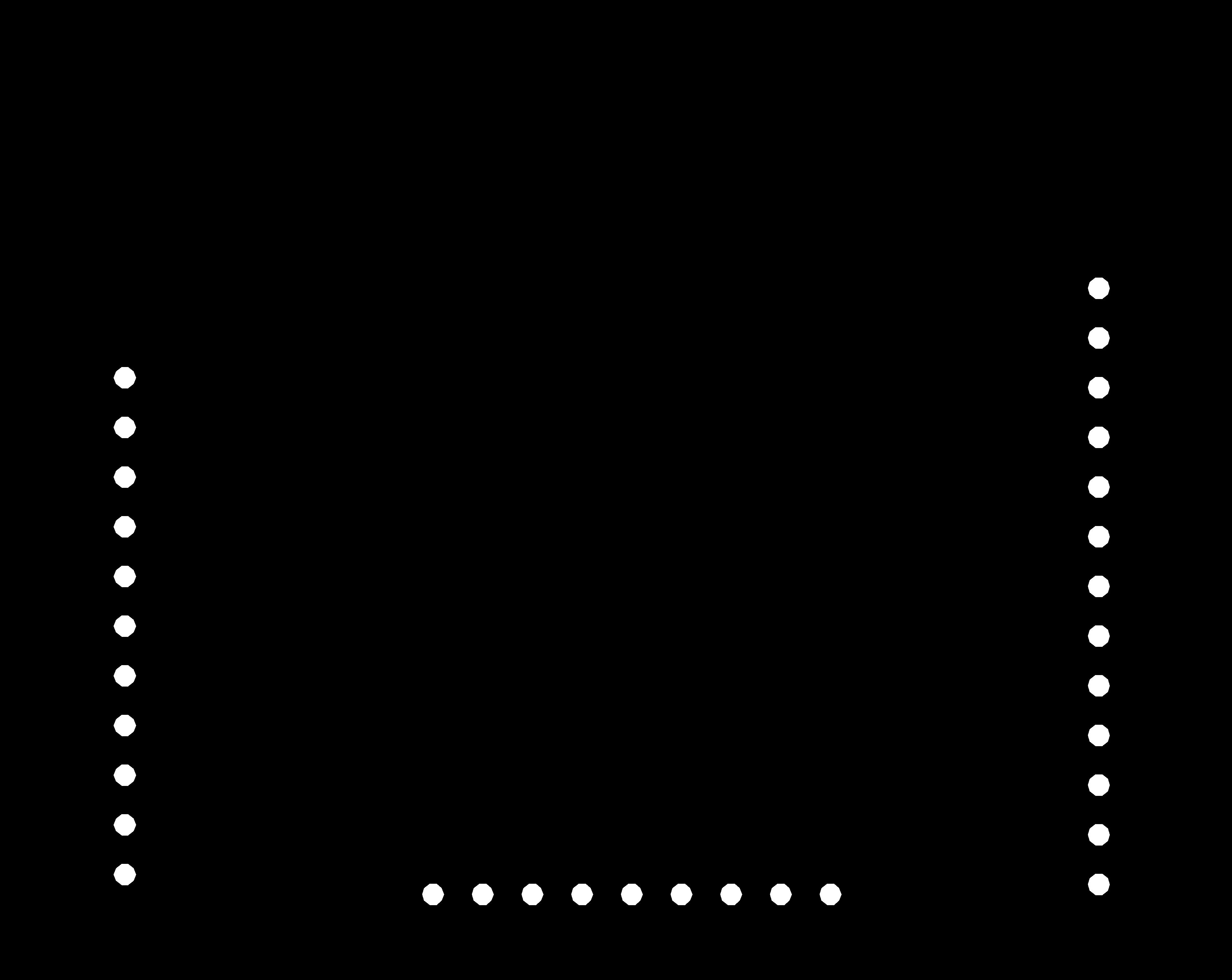
“BarDuino2.0_SwitchRelocate_BETA_cutout.png”

“BarDuino2.0_SwitchRelocate_BETA_trace.png.rml”

“BarDuino2.0_SwitchRelocate_BETA_holes.png-4.rml”

“BarDuino2.0_SwitchRelocate_BETA_cutout.png-2.rml”

“ESP32_Blynk_BLE_DriveSim_servo.ino”