Back To Top
Week 04 - Embedded Programming
Board Architectures
- Barduino 3.0
Barduino is an ESP32 compatible board created at Fab Lab Barcelona, by Eduardo Chamorro Martin with the help of Josep Marti and Oscar Gonzalez, since 2020. We are working with Barduino 3.0 (the fourth board created so far). It contains:
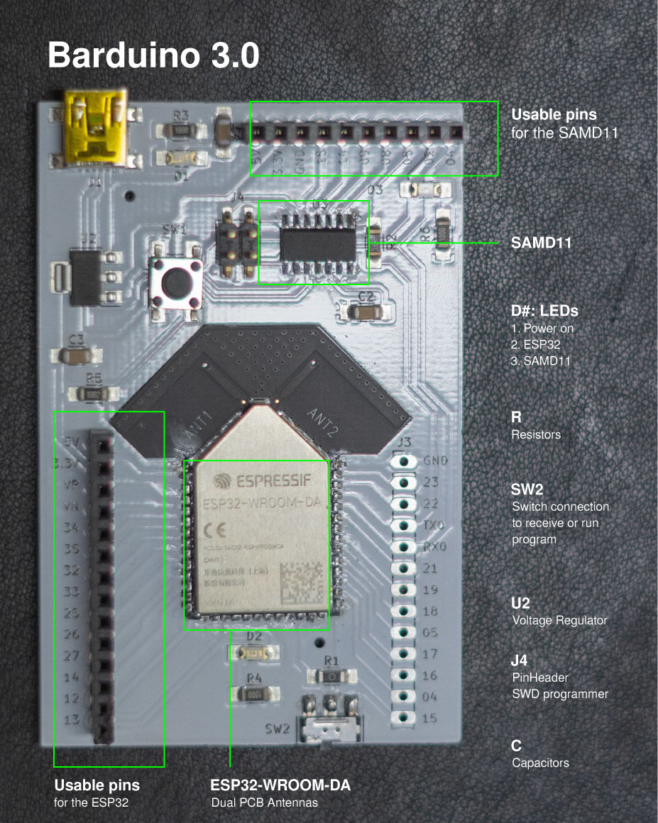
Programming Barduino 3.0:
- Arduino IDE: the first step is to run Arduino software in order to add in Additional Boards Manager URLs the links of the ESP32 and SAMD11 packages:
https://dl.espressif.com/dl/package_esp32_index.json
https://raw.githubusercontent.com/qbolsee/ArduinoCore-fab-sam/master/json/package_Fab_SAM_index.json
Then, under boards manager install them. - Programming SAMD11: We need to program the SAMD11 as a serial bridge, in other words, connect through USB the ESP32 to the computer. So the first step is to define the Serial configuration TWO UART NO WIRE NO SPI uploading the code.
Click here for the SAM11C serial code
The first step is in the Barduino 3.0 slide the switch to the left and press the reset button, this is to be in the flash mode and able to grite new code. Then, to flash the bootlader (a small piece of software that allows uploading of sketches onto the Arduino board.) from the Fab SAM core in here
- Programming the ESP32: Now that the SAMD11 is the serial bridge, we need to selected as the port. Now that the code is uploaded, slide the switch to the right side and restart the ESP31. If it works, the LED in GPIO13 should blink.
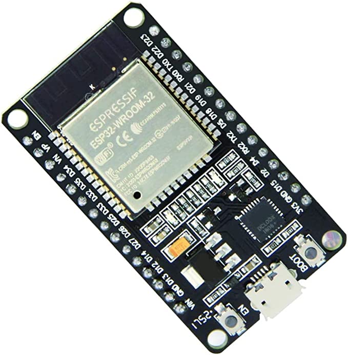
The ESP32 microcontroller
The ESP32 microcontroller has Wi-Fi and Blutooth connectivity integrated. ESP32 can perform as a standalone system or working with other microntrollers. It also has a low power consuption. ESP32 uses a 3.3 V system power supply.
ESP32 has many functionalities and we can divide those by sections to better undertand them.
- Power supply
The power supply can be digital, analogue and a real time clock power supply - RTC. - Power-on sequence and system reset
Power on sequence: the chip is activated after the power rails have stabilized. This is achieved by delaying the activation of CHIP_PU after the 3.3 V rails have been brought up. There is also a reset pin (CHIP_PU). - Flash (compulsory) and SRAM (optional)
ESP32 requires SiP flash or external flash to store application firmware and data. SiP PSRAM or external RAM is optional.
ESP32 can support up to 16 MB external flash and 8 MB external RAM (we need to select appropriate externalflash and RAM according to the power voltage on VDD_SDIO)
- Clock sources
There are two clock sources for the ESP32: an external 40 MHz crystal clock source oscillator and an RTC clock source to act as the RTC sleep clock. - RF (radio frequency)
The effective resistence/alternating current of the RF in ESP32 are SP32 (QFN 6*6) 30+j10)Ω and SP32 (QFN 5*5) 35+j10)Ω. - ADC (analogue to digital converter)
An ADC is used to convert an analog signal such as voltage to a digital form so that it can be read and processed by a microcontroller. - External capacitors
RC circuit between CAP1 and CAP2 pins (may be omitted under certain conditions) is used when entering deep-sleepmode. During this process, to minimize power consumption, the voltage to power ESP32 internals is dropped from 1.1 V to around 0.7 V. The RC circuit is used to minimize the period of the voltage drop. - UART (universal asynchronous receiver-transmitter)
UART allows asynchronous serial communication in which the data format and transmission speeds are configurable (users need to connect a 499Ω resistor to the U0TXD line in order to suppress the 80 MHz harmonic). - SDIO (secure digital input output)
SDIO is a type of secure digital card interface. It can be used as an interface for input or output devices. There are two sets of GPIOs (slot0 and slot1) that can be assigned to SDIO on ESP32. - Touch Sensor
ESP32 offers up to 10 capacitive IOs that detect changes in capacitance on touch sensors due to finger contact or proximity. The chip’s internal capacitance detection circuit features low noise and high sensitivity. It allows users touse touch pads with smaller area to implement the touch detection function. Users can also use the touch panelarray to detect a larger area or more test points.
Pin layout of the ESP32
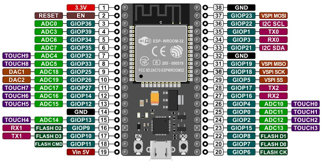
ESP32 has a lot of functionalities that allow multiple ways of input and output but, one important thing to know is that it can't communicate to the computer directly, so we need to use another controller, the SAMD 11 to make the bridge between them.
The ESP32-WROOM-DA microcontroller
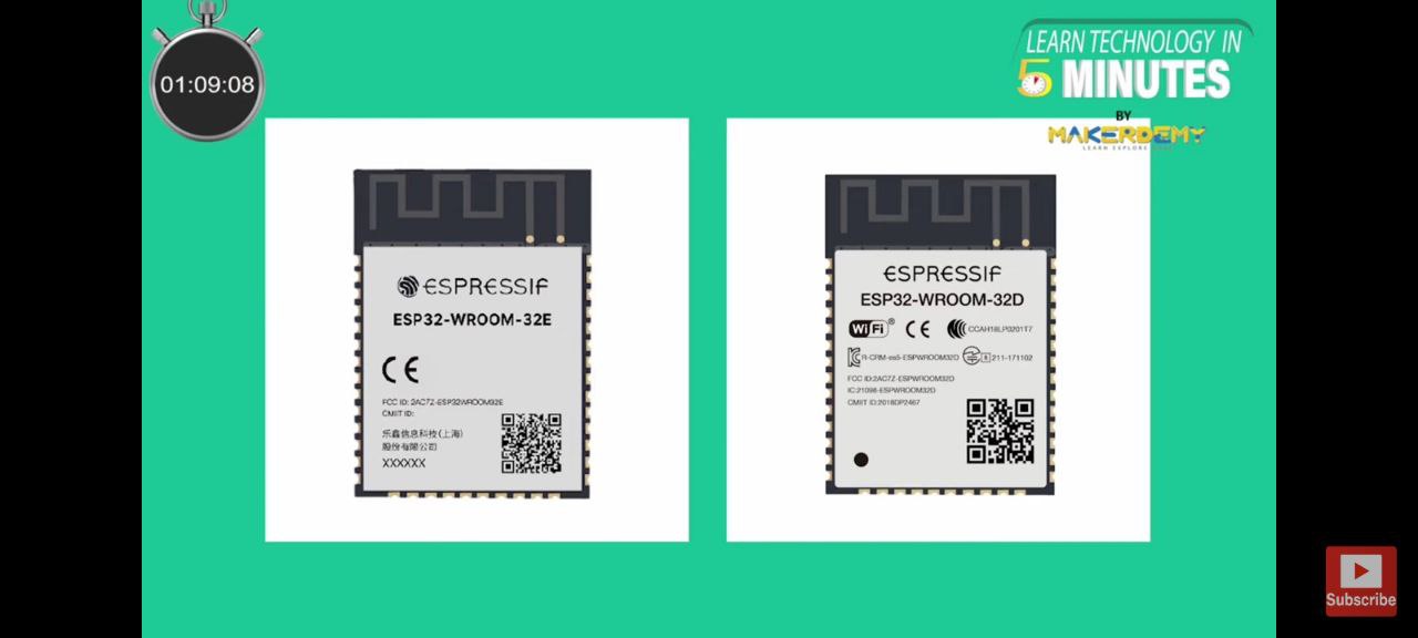
At fablab BCN we use the ESP32-WROOM-DA which is compatible with the ESP32-WROOM-32E. Because of the unique antenna design the ESP32-WROOM-DA has excellent wireless communication which can come quite handy for all our projects.
Main advantage of ESP32-WROOM-DA is posibility for long-range Wi-Fi communication, Provide wireless connectivity in a challenging environment.
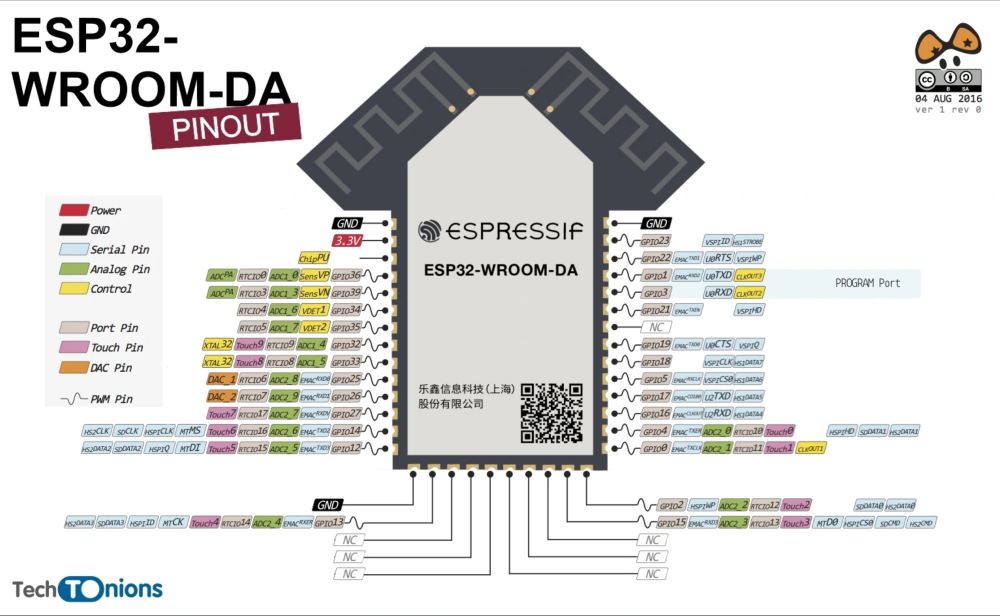
- ESP32-WROOM-DA pin-compatible with ESP32-WROOM-32E and ESP32-WROOM-32D.
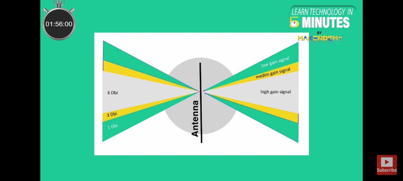
- ESP32-WROOM-DA module will have two complementary PCB antennas in different directions, apart this ESP32-WROOM-DA have its already existing.
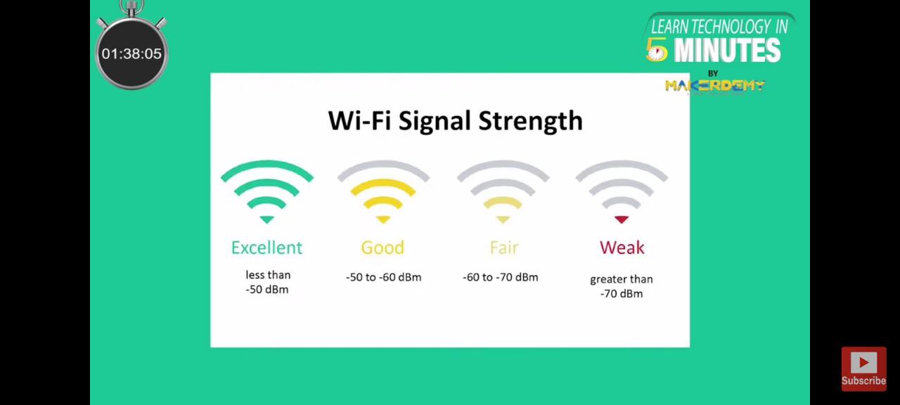
- For handing 2 complementary antennas together, the module work according to the strength of the signal. It select the strongest signal to maintain continuous communication. While working, if the strength of the signal drops, the module will send an API call to help the module switch to the other antenna to maintain high signal strength. Unlike the old ESP32 modules, antennas are less omnidirectional and thus would offer greater antenna gain.
-
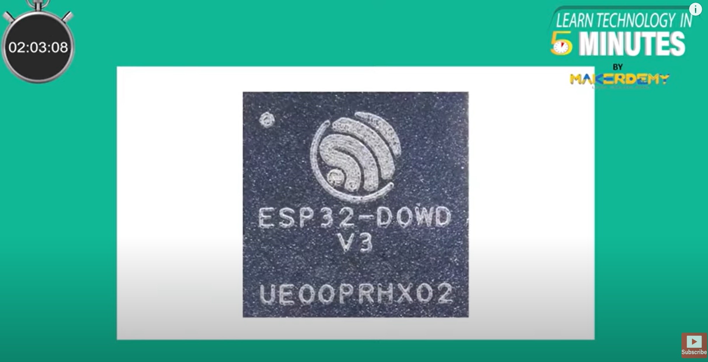
The ESP32-WROOM-DA module have an in-built ESP32-D0WD-V3 chip. Hence we can say, ESP32-WROOM-DA will have the following :
- dual-core Xtensa LX6 processor the maximum frequency of 240MHz
- 520KB of SRAM
- 448KB of ROM
- 4MB SPI flash
- Detailed specifications of ESP32-WROOM-DA>
- Operating voltage of 3 to 3.6V
The SAMD 11 microcontroller
The Atmel® | SMART™ SAM D11 is a series of general purpose and low-power microcontrollers using the 32-bit ARM® Cortex®-M0+ 32-bit processor, the one used by us (SAMD11C14A) with 14 pins with 16KB Flash and 4KB SRAM. SAM D11 devices operate at a maximum frequency of 48MHz and achieve 2.46 Coremark/MHz. They are designed for easy and intuitive migration with identical peripheral modules, hexadecimal compatible code, identical linear address map and migration paths between all devices in the series.
Some of the SAMD functionalities are discussed below:
- Memories
16KB in-system self-programmable Flash and 4KB SRAM Memory. - System
Power-on reset (POR) and brown-out detection (BOD)
Internal and external clock options with 48MHz Digital Frequency Locked Loop (DFLL48M) and 48MHz to 96MHz Fractional
Digital Phase Locked Loop (FDPLL96M)
External Interrupt Controller (EIC)
8 external interrupts
One non-maskable interrupt
Two-pin Serial Wire Debug (SWD) programming, test and debugging interface - Peripherals
6-channel Direct Memory Access Controller (DMAC)
6-channel Event System
Two 16-bit Timer/Counters (TC)
One 24-bit Timer/Counters for Control (TCC)
32-bit Real Time Counter (RTC) with clock/calendar function
Watchdog Timer (WDT)
CRC-32 generator
One full-speed (12Mbps) Universal Serial Bus (USB) 2.0 interface
Up to three Serial Communication Interfaces (SERCOM)
12-bit, 350ksps Analog-to-Digital Converter (ADC) with up to 10 channels
10-bit, 350ksps Digital-to-Analog Converter (DAC)
Two Analog Comparators (AC) with window compare function
Peripheral Touch Controller (PTC) - Operating Voltage
1.62V – 3.63V
Pin layout of the SAMD11C14A

- Arduino
An Arduino board is a microcontroller-based development board that features an Atmel AVR microcontroller, which is the central processing unit of the board. The architecture of an Arduino board is based on a Harvard architecture, which means that the program memory and data memory are separate and accessed using different buses.
The Atmel AVR microcontroller used in an Arduino board typically has a RISC (Reduced Instruction Set Computing) architecture, which means that it uses a small set of simple and efficient instructions that can be executed quickly. The AVR microcontroller also has a 8-bit or 32-bit architecture, depending on the specific model used in the Arduino board.
In addition to the microcontroller, an Arduino board typically includes a number of other components, including power supply circuitry, a clock oscillator, a USB-to-serial converter, and input/output pins that can be used to interface with external devices. These components are arranged on a printed circuit board (PCB) that is designed to be easy to use and program, even for people without a lot of electronics experience.
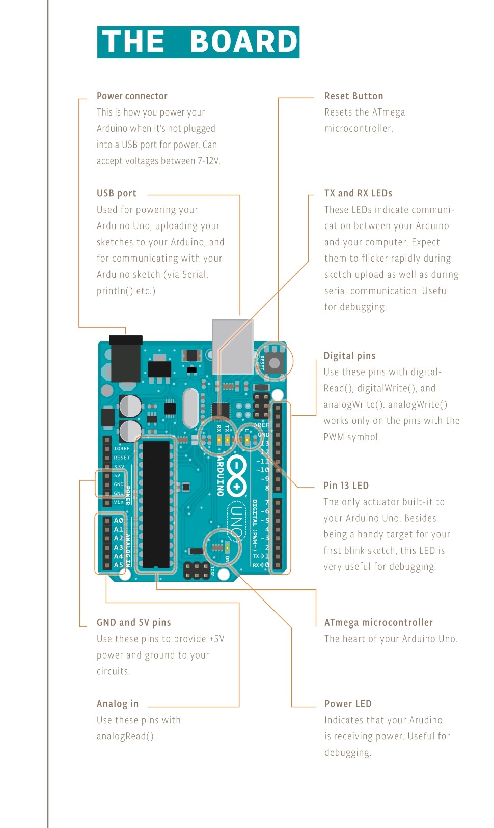
Here is a detailed view of the Arduino.
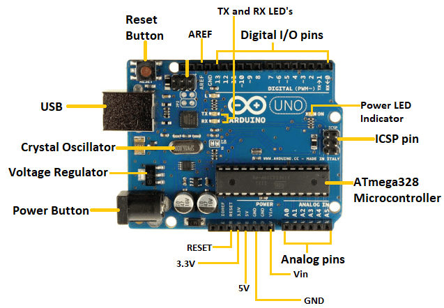
The following image is the pin layout for the Arduino board.
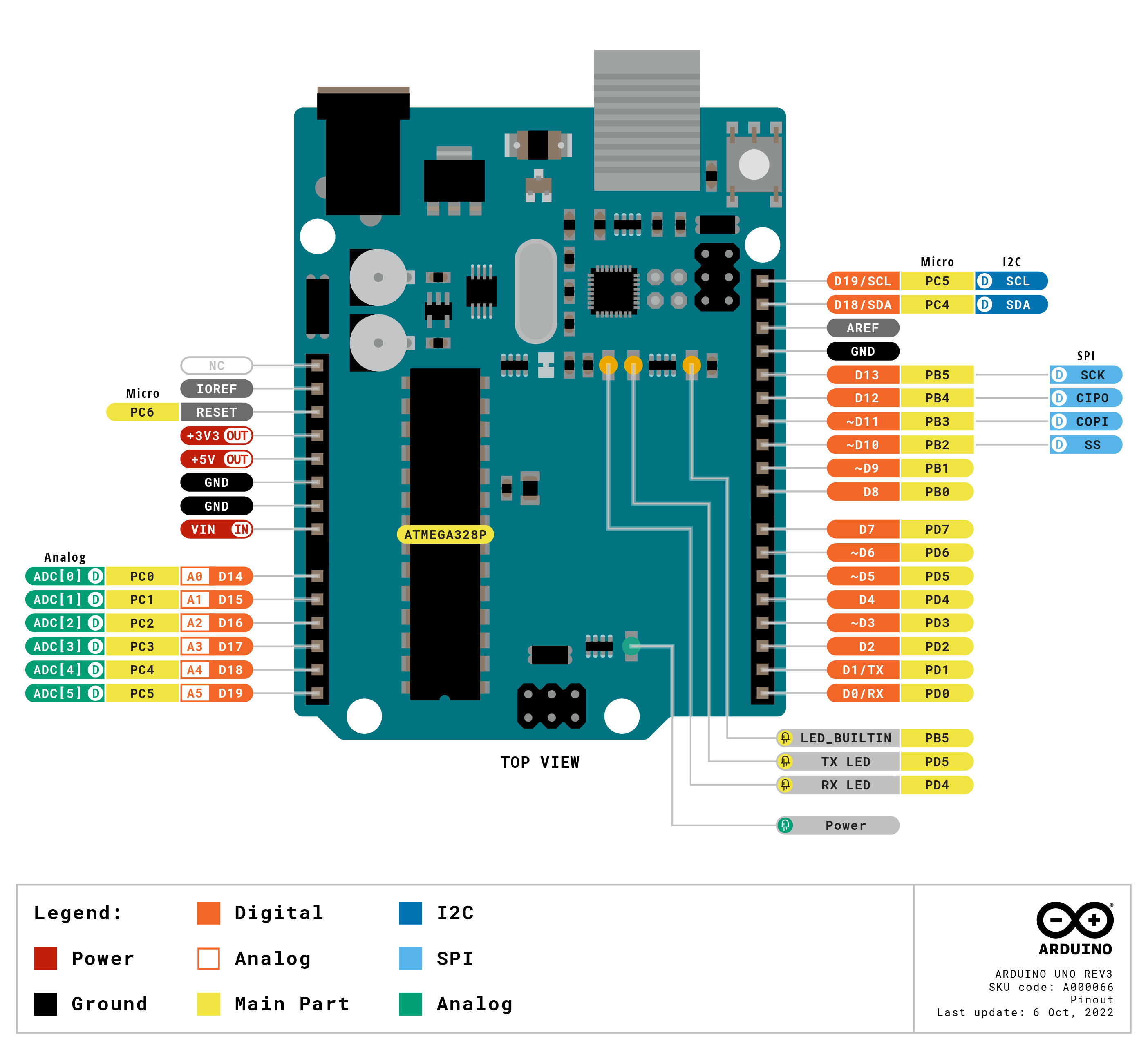
Click here to check the Arduino data sheet.
- ESP32 Vs. Arduino
When comparing Arduino to the ESP32, both are popular platforms for developing embedded systems and IoT devices, but they have some key differences. Here are some advantages and disadvantages of the Arduino platform compared to the ESP32.
Advantages of Arduino:
- Simplicity: Arduino is generally considered easier to use than the ESP32 due to its simpler programming language and IDE. It is a great platform for beginners who are just starting out with embedded systems and IoT development.
- Large Community: Arduino has a huge and supportive community of developers and enthusiasts who have developed libraries, code examples, and tutorials for various use cases. This makes it easier for beginners to get started and for experienced developers to build complex projects quickly.
- Wide Range of Hardware Options: Arduino boards come in a variety of sizes and form factors, which makes them suitable for a wide range of applications. They are available in small, low-power designs for battery-powered devices, as well as larger, more powerful boards for more demanding applications.
- Open Source: The Arduino platform is open source, which means that anyone can access and modify its design and software. This allows for a high degree of customization and flexibility.
Disadvantages of Arduino:
- Limited Processing Power: Arduino boards are generally less powerful than the ESP32, which can make them unsuitable for complex projects that require a lot of processing power or memory.
- Limited Connectivity Options: Arduino boards generally have limited connectivity options, which can make them unsuitable for projects that require advanced networking capabilities, such as Wi-Fi, Bluetooth, or cellular connectivity.
Advantages of ESP32:
- High Processing Power: The ESP32 is much more powerful than the Arduino, with dual-core processors and more memory, which makes it suitable for more complex and demanding projects.
- Advanced Connectivity Options: The ESP32 comes with built-in Wi-Fi, Bluetooth, and Ethernet connectivity, which makes it suitable for projects that require advanced networking capabilities.
- Built-in Security Features: The ESP32 has built-in security features such as secure boot, flash encryption, and hardware-accelerated cryptographic operations, which make it more secure than the Arduino.
Disadvantages of ESP32:
- Complexity: The ESP32 is generally considered more complex than the Arduino, both in terms of programming and hardware design. This can make it more difficult for beginners to get started with.
- Smaller Community: The ESP32 has a smaller community of developers and enthusiasts than the Arduino, which can make it harder to find resources and support.
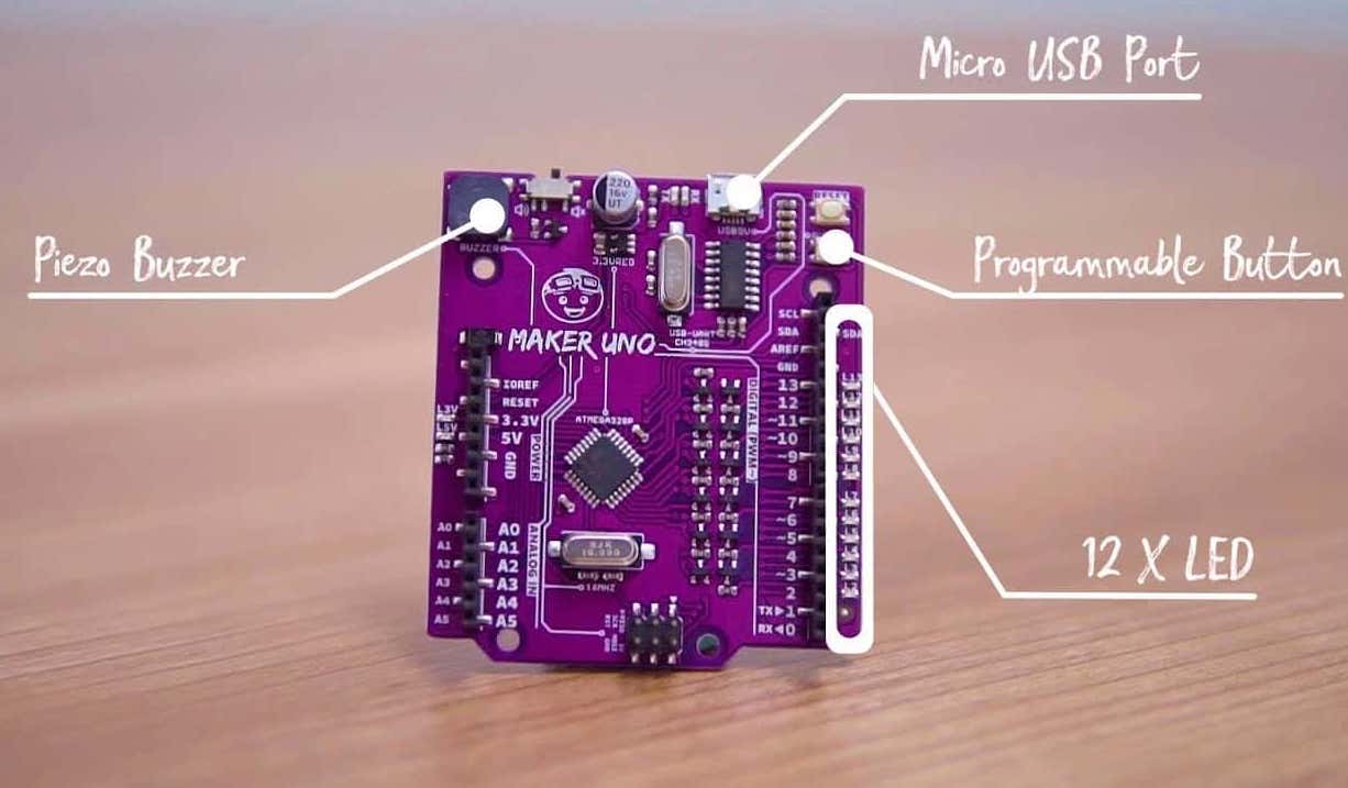
- Maker UNO
The Maker UNO (another board in our possession) is an Arduino UNO specifically designed for education.
What this means precisely is that it's made up of the exact same components as the Arduino Uno. However they have added a few key elements to help students and first time users with the process of developing a circuit board.
In terms of performance both boards are basically the same. Somewhere it differ is that it has a few additional components, as well as a CH340g chip instead of the ATMega16u2. These two chips act as a bridge between the computer's USB port and the main processor's serial port. With the CH340g, the Maker UNO can only ever be detected as a plain serial device whereas the 16u2 can be used as a another type of device such as a keyboard, joystick or soundcard... In addition to this, the CH340g is cheaper than the Arduino UNO chip.
A comparison table of the two PCBs:
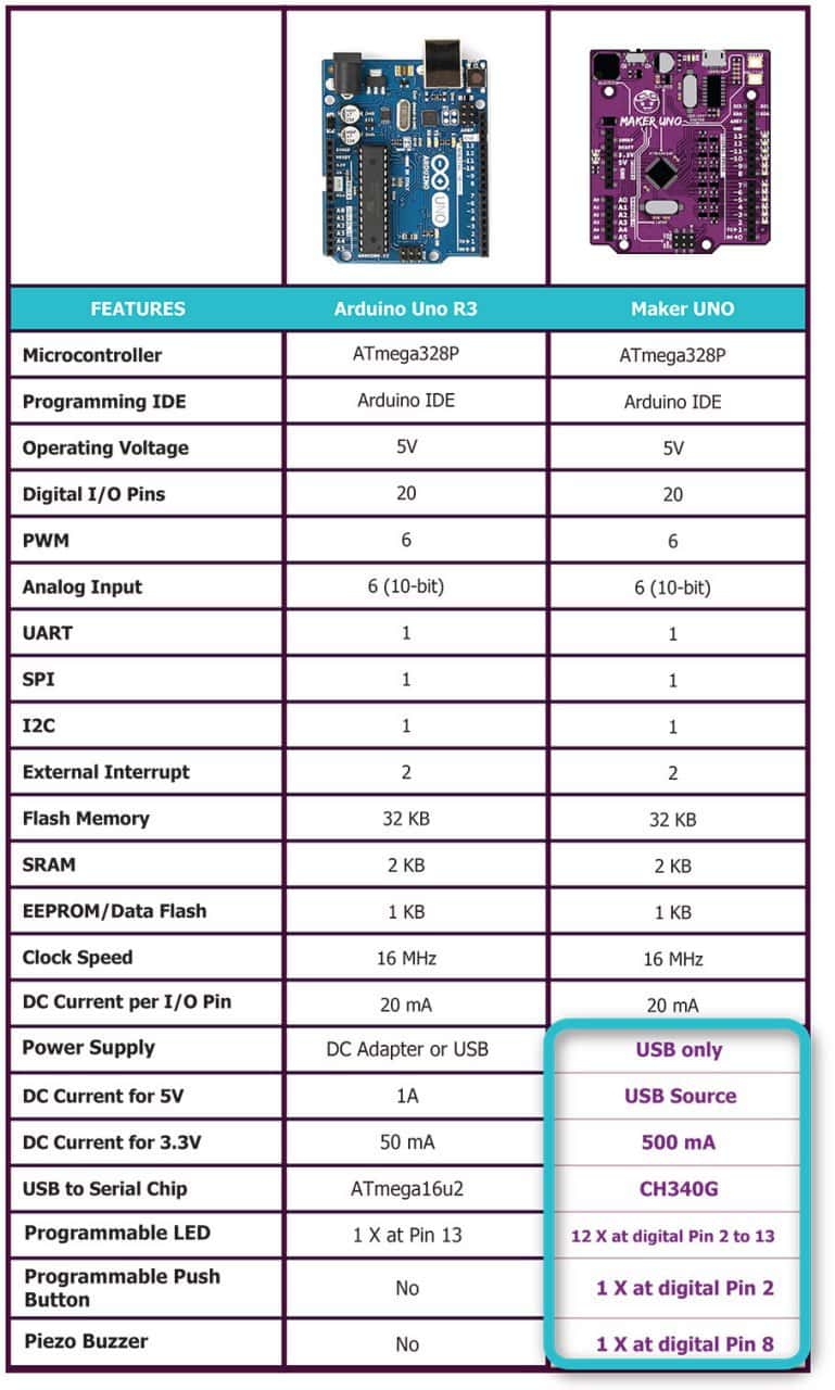
Its main additional features are 12 LEDs, one on each of the numbered the pins of the board, a programmable button and a buzzer. This aims to accelerate the learning curve when it comes to the development of the board as well as a potentially faster/easier debugging process.
Take this blink.ino example: On a normal Arduino UNO, you would have to create a basic electronic circuit where each pin is connected to an LED before being able to get to something like what we've developed below:
Conclusion:
Our experience shows that in this case the Maker UNO allowed us to focus on the development of the code rather than the design of the electronics. Wether this is an improvement from the Arduino UNO itself is arguable. But at least these extra features do not really make the Maker UNO a competitor to Arduino, however what it does to is that it highlights what the Arduino project is actually about, and why it is such a game-changer: It’s the ability to build on top, modify and improve on their technology to cater for different purposes, and in particular education.