11. Input devices
Group 1 (Ito-Yamada)
This is the group assignment of the week.
- probe an input device’s analog levels and digital signals
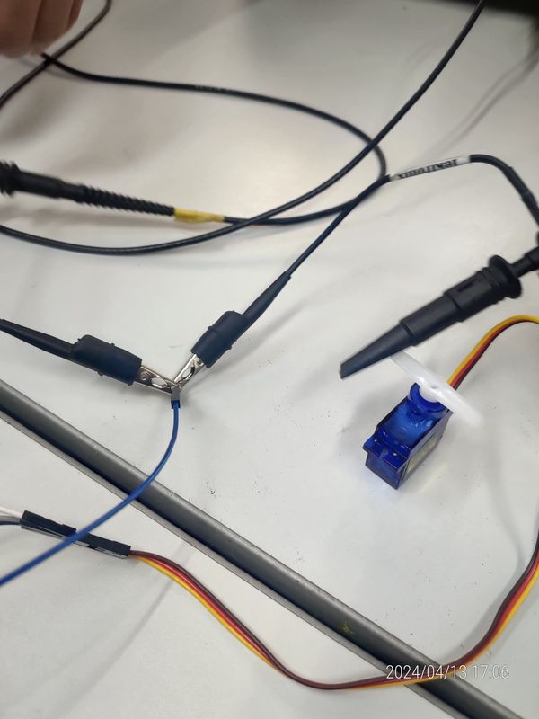
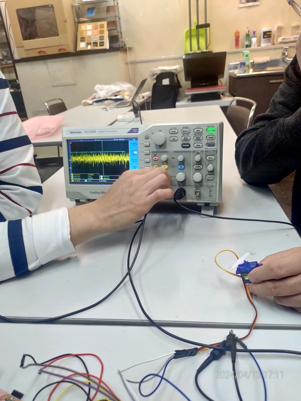
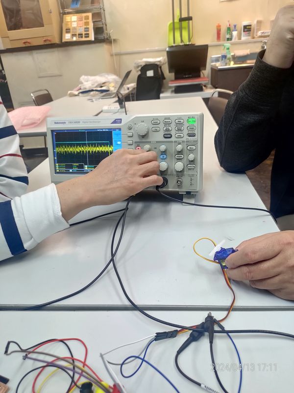
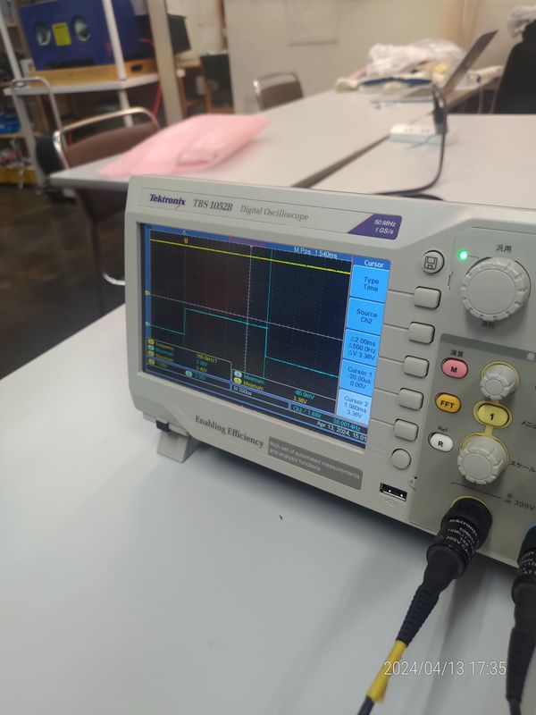
In this Group Assignment, we will control the servo motor used in Week 9’s Individual Assignment with a volume switch and observe the signal using an oscilloscope. The control panel is equipped with many switches, which seem quite challenging to master. Initially, we will receive a lecture on how to use the oscilloscope from our instructor.
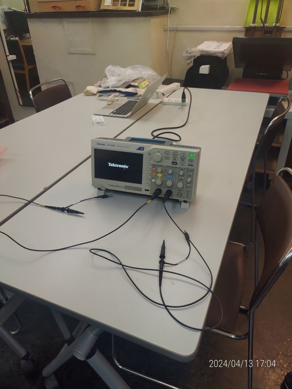
Next, to confirm our understanding, we will actually perform the same tasks ourselves.
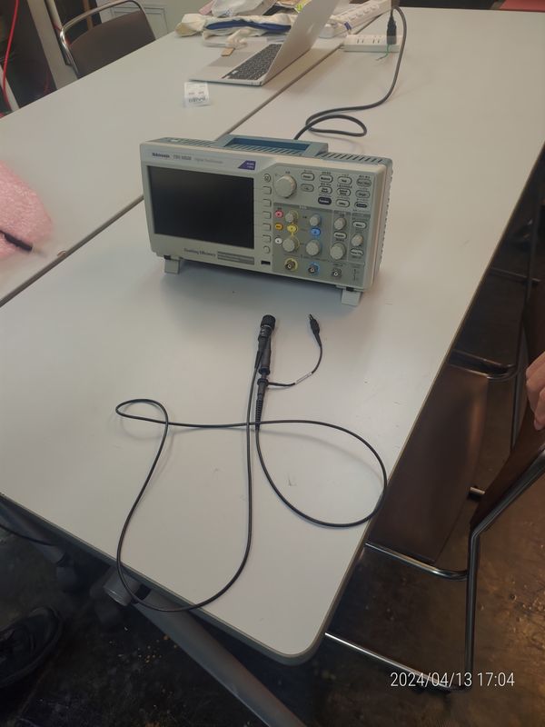
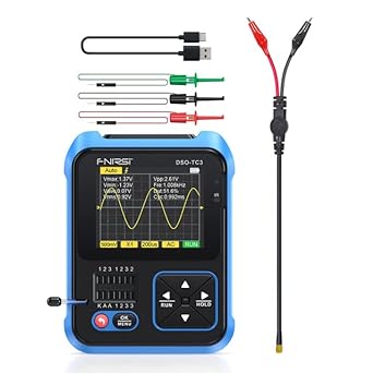
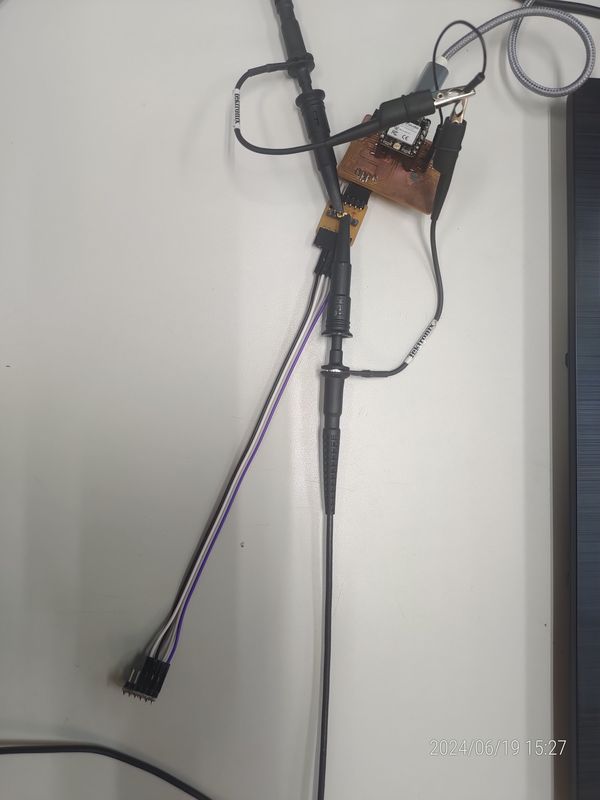
The oscilloscope we will use is the FNIRSI DSO-TC3.
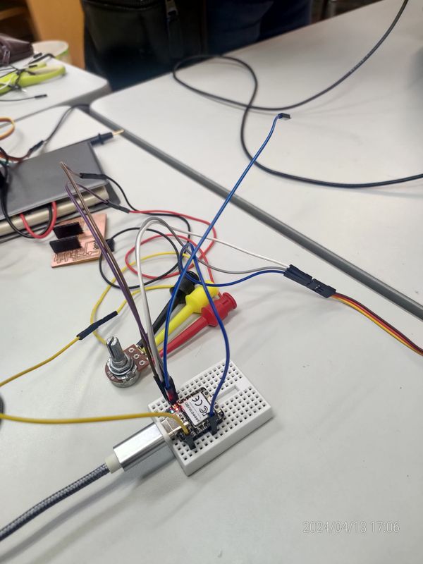
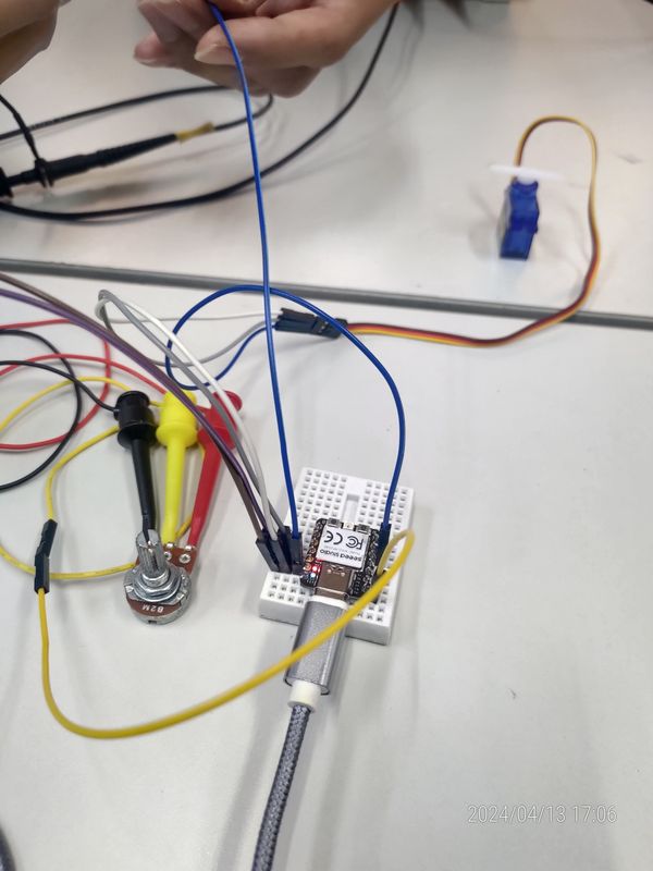
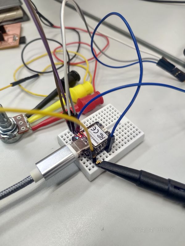
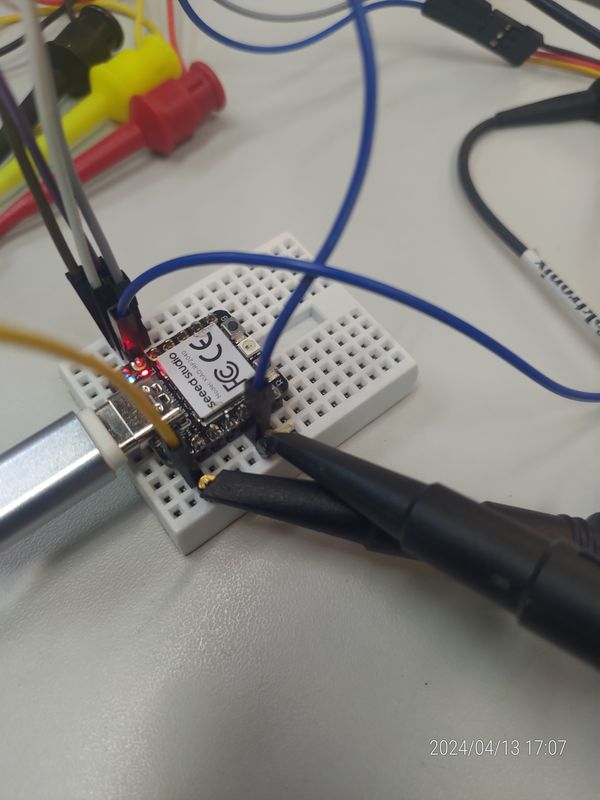
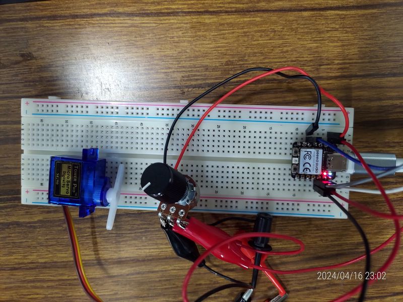
The execution environment will be the same as explained during the lecture, using a breadboard connected to a SG90 servo motor, RP2040, and a volume switch.
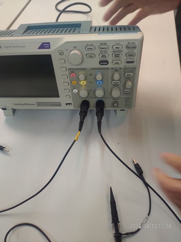
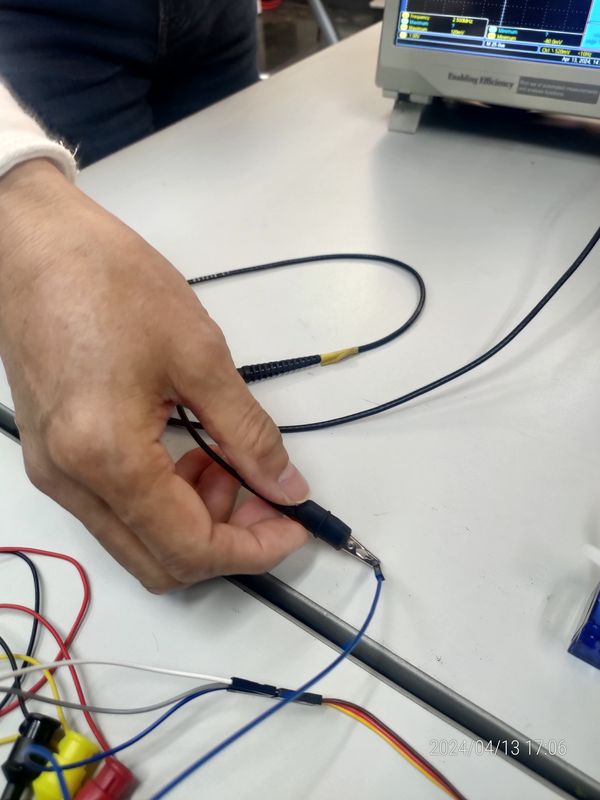
Finally, all that is left is to connect the oscilloscope to the analog inputs and digital outputs, and then we are ready to begin.
Download sample program:
File->Examples->Servo->Sweep
I updated the pin number in the source code from 9 to 6 to reflect the servo being connected to pin 6.
/*
 Controlling a servo position using a potentiometer (variable resistor)
 by Michal Rinott <http://people.interaction-ivrea.it/m.rinott>
 modified on 8 Nov 2013
 by Scott Fitzgerald
 http://www.arduino.cc/en/Tutorial/Knob
*/
#include <Servo.h>
Servo myservo;  // create servo object to control a servo
int potpin = A0;  // analog pin used to connect the potentiometer
int val;    // variable to read the value from the analog pin
void setup() {
  myservo.attach(6);  // attaches the servo on pin 6 to the servo object
}
void loop() {
  val = analogRead(potpin);            // reads the value of the potentiometer (value between 0 and 1023)
  val = map(val, 0, 1023, 0, 180);     // scale it for use with the servo (value between 0 and 180)
  myservo.write(val);                  // sets the servo position according to the scaled value
  delay(15);                           // waits for the servo to get there
}
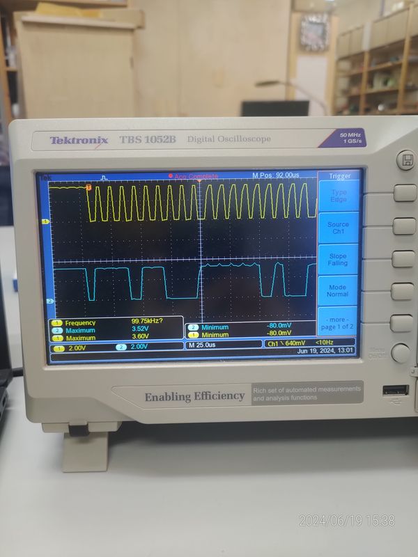
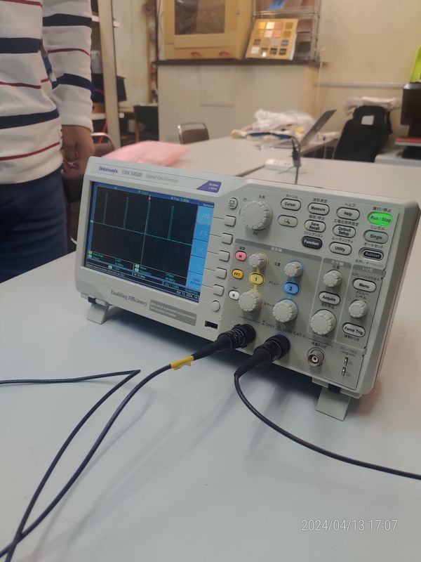
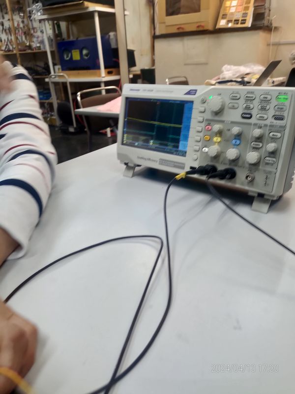
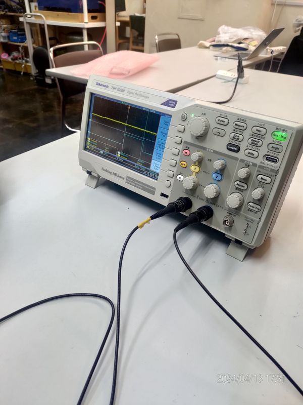
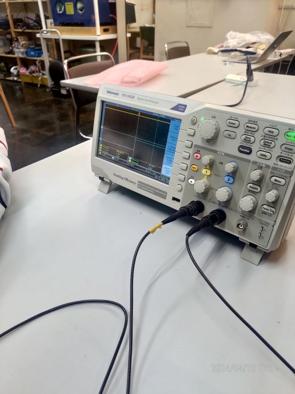
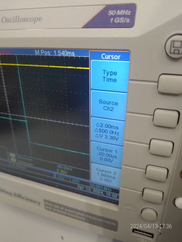
After executing the program, we will turn the Volume Switch clockwise and observe the changes in the waveform.
By turning the adjustment knob, the pulse width is changed, which is used for controlling the position of the servo motor.
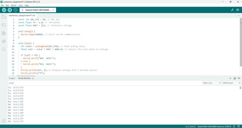
Probing1 Soil moisture sensor
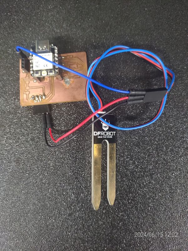
This code is a conversion of MicroPython code for use with Arduino. The voltage output by the sensor varies between 0 and 3.3V depending on the soil moisture. If the voltage is 1V or higher, it is considered wet and “Wet” is displayed. If it is below 1V, it is considered dry and “Dry” is displayed.
const int ADC_PIN = A0; // ADC pin
const float TH = 1.0; // Threshold
const float VREF = 3.3; // Reference voltage

void setup() {
  Serial.begin(9600); // Start serial communication
}

void loop() {
  int value = analogRead(ADC_PIN); // Read analog value
  float volt = value * VREF / 1023.0; // Convert to voltage

  if (volt > TH) {
    Serial.print("Wet  Volt:");
  } else {
    Serial.print("Dry  Volt:");
  }
  Serial.print(volt, 2); // Display voltage
  Serial.println("V");

  delay(500); // Wait for 0.5 seconds
}
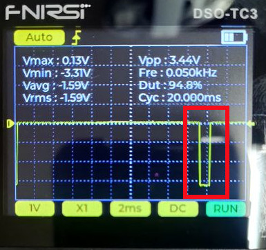
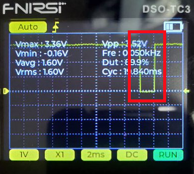
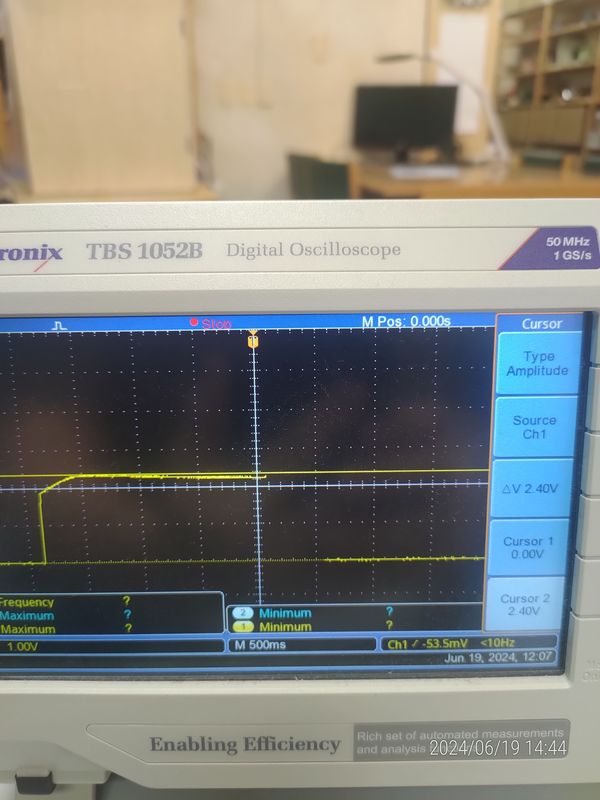
Execution Results:
When the probe is not touching anything, it displays Dry around 0.1V. However, when the probe is submerged in water, the voltage rises to 3.85V and it changes to Wet.
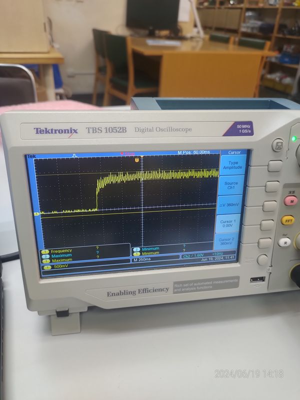
Here are the values when holding the sensor by fingers.
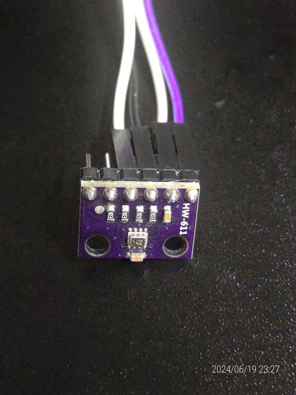
Probing2 Combined humidity and pressure sensor(BMP280)
/*
  This program reads atmospheric pressure, temperature and approximate altitude from an Atmospheric
  Pressure Sensor(GY-BMP280-3.3) using an Arduino Uno board. It uses the Adafruit BMP280 library to
  interface with the sensor, and prints the readings to the Serial Monitor.

  Board: Arduino Uno R4 (or R3)
  Component: Atmospheric Pressure Sensor(GY-BMP280-3.3)
  Library: https://github.com/adafruit/Adafruit_BMP280_Library  (Adafruit BMP280 by Adafruit)
*/

#include <Wire.h>
#include <SPI.h>
#include <Adafruit_BMP280.h>
#define BMP280_ADDRESS 0x76
Adafruit_BMP280 bmp;  // use I2C interface

void setup() {
  Serial.begin(9600);          // initialize serial communication with baud rate of 9600
  while (!Serial) delay(100);  // wait for native usb
  Serial.println(F("BMP280 test"));

  unsigned status;
  status = bmp.begin(BMP280_ADDRESS);
  if (!status) {
    Serial.println(F("Could not find a valid BMP280 sensor, check wiring or "
                     "try a different address!"));
    while (1) delay(10);  // Stop code execution if the sensor is not found.
  }

  /* Default settings from datasheet. */
  bmp.setSampling(Adafruit_BMP280::MODE_NORMAL,     /* Operating Mode. */
                  Adafruit_BMP280::SAMPLING_X2,     /* Temp. oversampling */
                  Adafruit_BMP280::SAMPLING_X16,    /* Pressure oversampling */
                  Adafruit_BMP280::FILTER_X16,      /* Filtering. */
                  Adafruit_BMP280::STANDBY_MS_500); /* Standby time. */
}

void loop() {
  // Read and print temperature in degrees Celsius.
  Serial.print(F("Temperature = "));
  Serial.print(bmp.readTemperature());
  Serial.println(" °C");

  //Read and print atmospheric pressure in hectopascals (hPa).
  Serial.print(F("Pressure = "));
  Serial.print(bmp.readPressure());
  Serial.println(" hPa");

  //Read and print approximate altitude based on standard pressure (1013.25 hPa).
  Serial.print(F("Approx altitude = "));
  Serial.print(bmp.readAltitude(1013.25));
  Serial.println(" m");

  Serial.println();  // Print a blank line to separate readings.
  delay(2000);       // Wait for 2 seconds before taking the next set of readings.
}
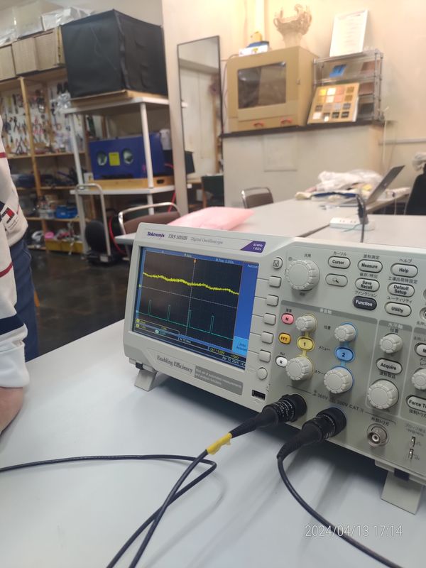
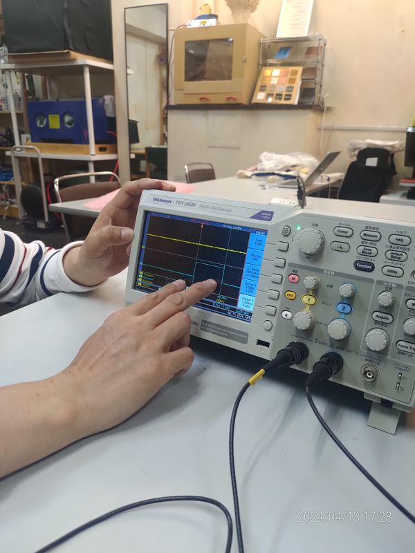
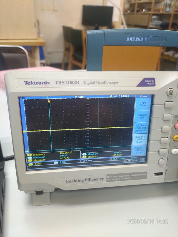
Execution Results:
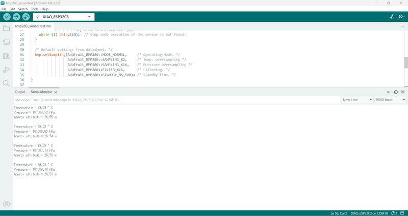
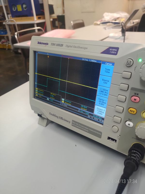
The yellow line at the top of the screen represents the SDA data waveform, while the blue line at the bottom represents the SCL data waveform.