
Week 14
Introduction
This page outlines the steps followed during week 14 of the Fab Academy assignments.
The tasks for this week involved Interface and Application Programming and the following assignments:
- Compare as many tool options as possible
- Write an application that interfaces a user with an input &/or output device that you made.
group assignment:
Individual assignment:
Let's start.....................

Group assignment
The group assignment for this week was to compare as many tool options as possible. This involved researching and analyzing different tools that can be used for interface and application programming. The goal was to understand the strengths and weaknesses of each tool, as well as their suitability for different applications.
I analized the following tools for interface and application programming:
- React
- App Inventor
- Adafruit IO
React

Image source REACT
React is a JavaScript library for building user interfaces. It allows developers to create reusable UI components and manage the state of their applications efficiently. React is widely used for web development and has a large community and ecosystem of libraries and tools.
Advantages:
- Component-based architecture
- Virtual DOM for performance optimization
- Large community and ecosystem
- Rich set of libraries and tools
Disadvantages:
- Steep learning curve for beginners
- Requires knowledge of JavaScript and JSX
- Can be overkill for simple applications
Also, REACT let us to create applications that can be used to control devices like Raspberry Pi creating an executable file that can be run on the computer. This is posible with the help of Kubernetes, Docker and Node.js.
- Docker: is a platform that allows developers to automate the deployment of applications inside lightweight containers.
- Kubernetes: is an open-source container orchestration platform that automates the deployment, scaling, and management of containerized applications.
- Node.js: is a JavaScript runtime built on Chrome's V8 JavaScript engine that allows developers to build scalable network applications.
This option was originally considered for the final project, but might be discarded due to the complexity of the tools involved. The learning curve for these tools is steep and it would may require a significant amount of time and effort to master them. Additionally the project requires a more straightforward approach to interface and application programming. However, it is relatively easy to integrate all the hardware drivers or scripts that we create to control the devices with the interface built using REACT.
APP Inventor
App Inventor is a visual programming environment that allows users to create mobile applications for Android devices. It uses a block-based programming language, making it accessible to beginners and non-programmers. App Inventor is particularly useful for creating simple applications quickly and easily.
Advantages:
- Visual programming environment
- Easy to learn and use
- Quick prototyping of mobile applications
- Good for educational purposes
Disadvantages:
- Limited functionality compared to traditional programming languages
- Not suitable for complex applications
- Limited customization options
App Inventor is a good option for creating simple applications quickly and easily. It is particularly useful for educational purposes and for users who are new to programming. However, it may not be suitable for more complex applications that require advanced functionality and customization.
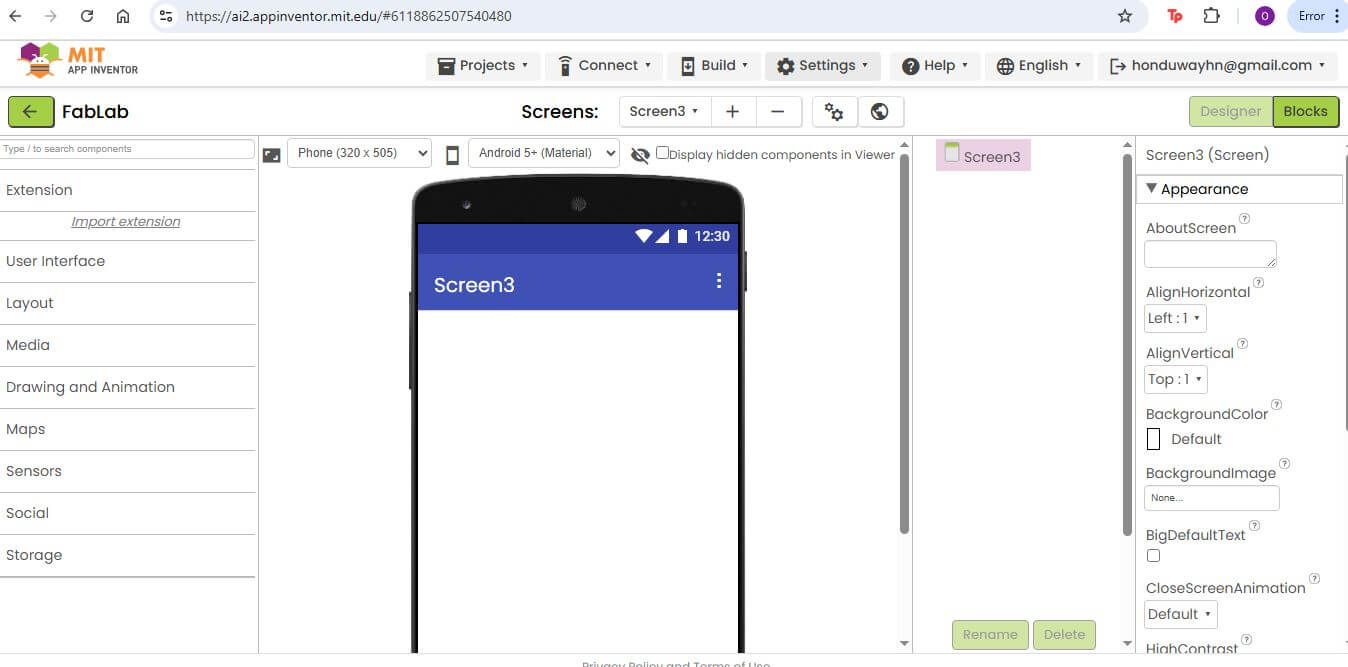
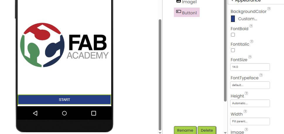
We try to use App Inventor to create an application that can display info for an accelerometer with BLE connection, however the platform is under maintenance and we couldn't use BLE connection, Because the option was not available.
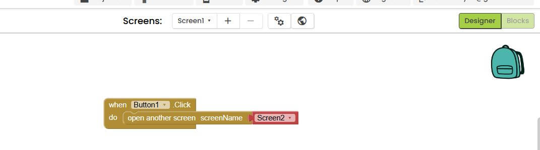
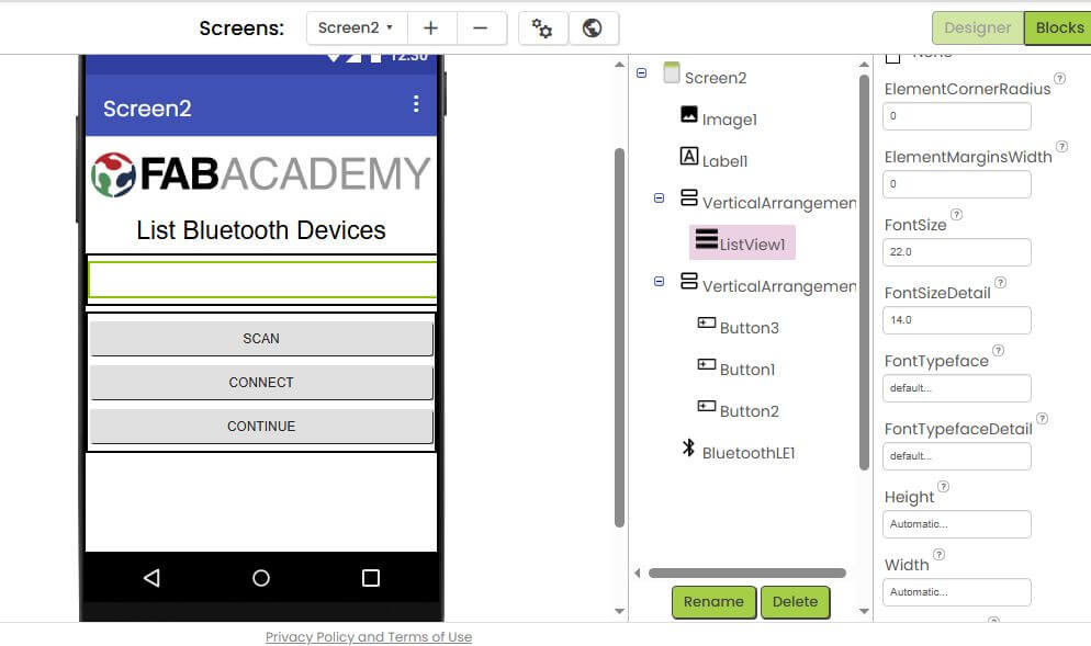
The interface is very simple and easy to use, however the platform is not very flexible and it is not possible to create complex applications. The platform is very limited and it is not possible to create complex applications. To code the application we need to use a block programming language, which is not very flexible.
Adafruit IO
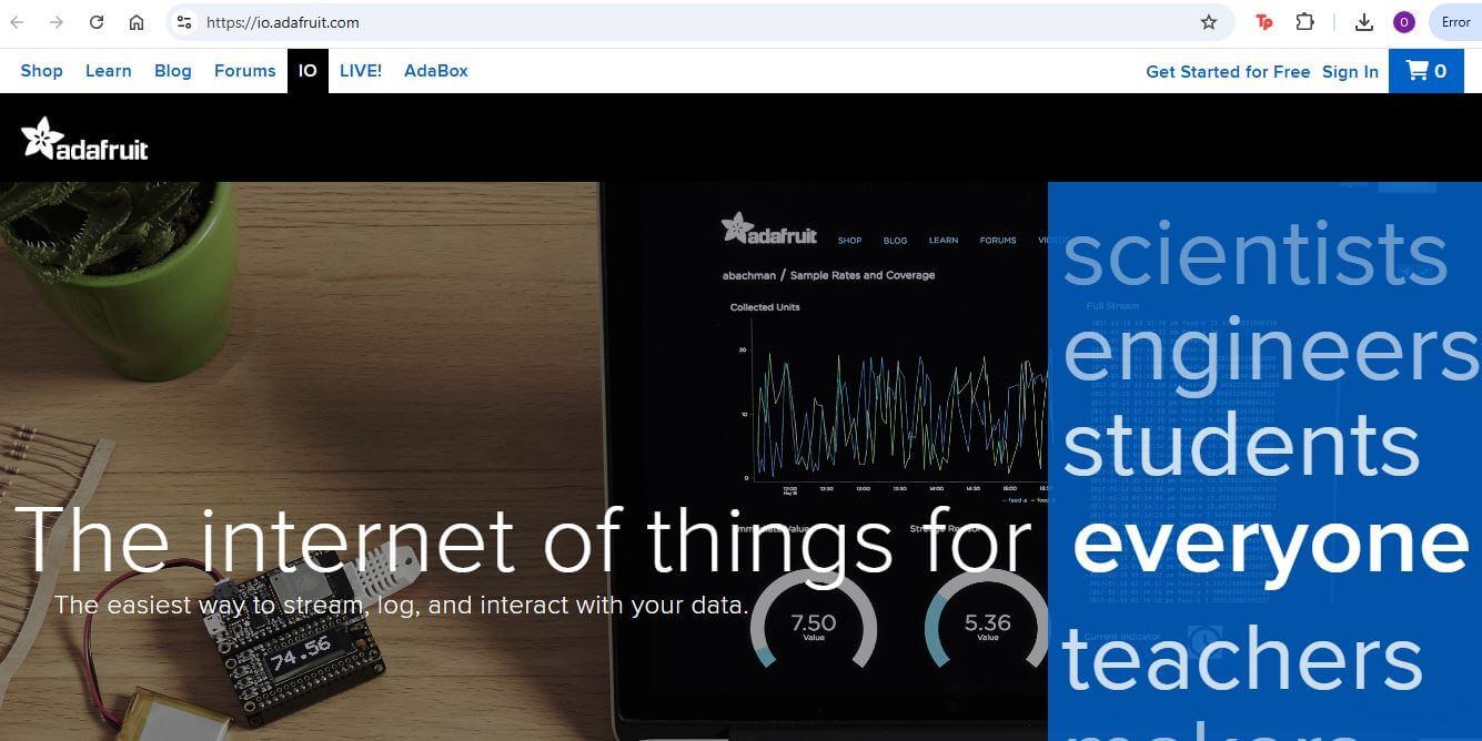
Adafruit IO is a cloud-based platform for IoT (Internet of Things) applications. It allows users to connect devices, collect data, and visualize it in real-time. Adafruit IO provides a user-friendly interface and supports various protocols, including MQTT and HTTP. It is particularly useful for projects that require remote monitoring and control of devices.
Advantages:
- Cloud-based platform for IoT applications
- User-friendly interface
- Supports various protocols (MQTT, HTTP)
- Real-time data visualization
Disadvantages:
- Requires internet connection
- Limited functionality compared to traditional programming languages
- Subscription fees for advanced features
Adafruit IO is a good option for projects that require remote monitoring and control of devices. It provides a user-friendly interface and supports various protocols, making it easy to connect devices and collect data. However, it may not be suitable for applications that require advanced functionality and customization. Additionally, it requires an internet connection and may incur subscription fees for advanced features.
Individual assignment
The individual assignment for this week was to write an application that interfaces a user with an input and/or output device that you made. This involved creating a user interface and writing the necessary code to communicate with the device. The goal was to demonstrate the ability to create a functional application that interacts with hardware components.
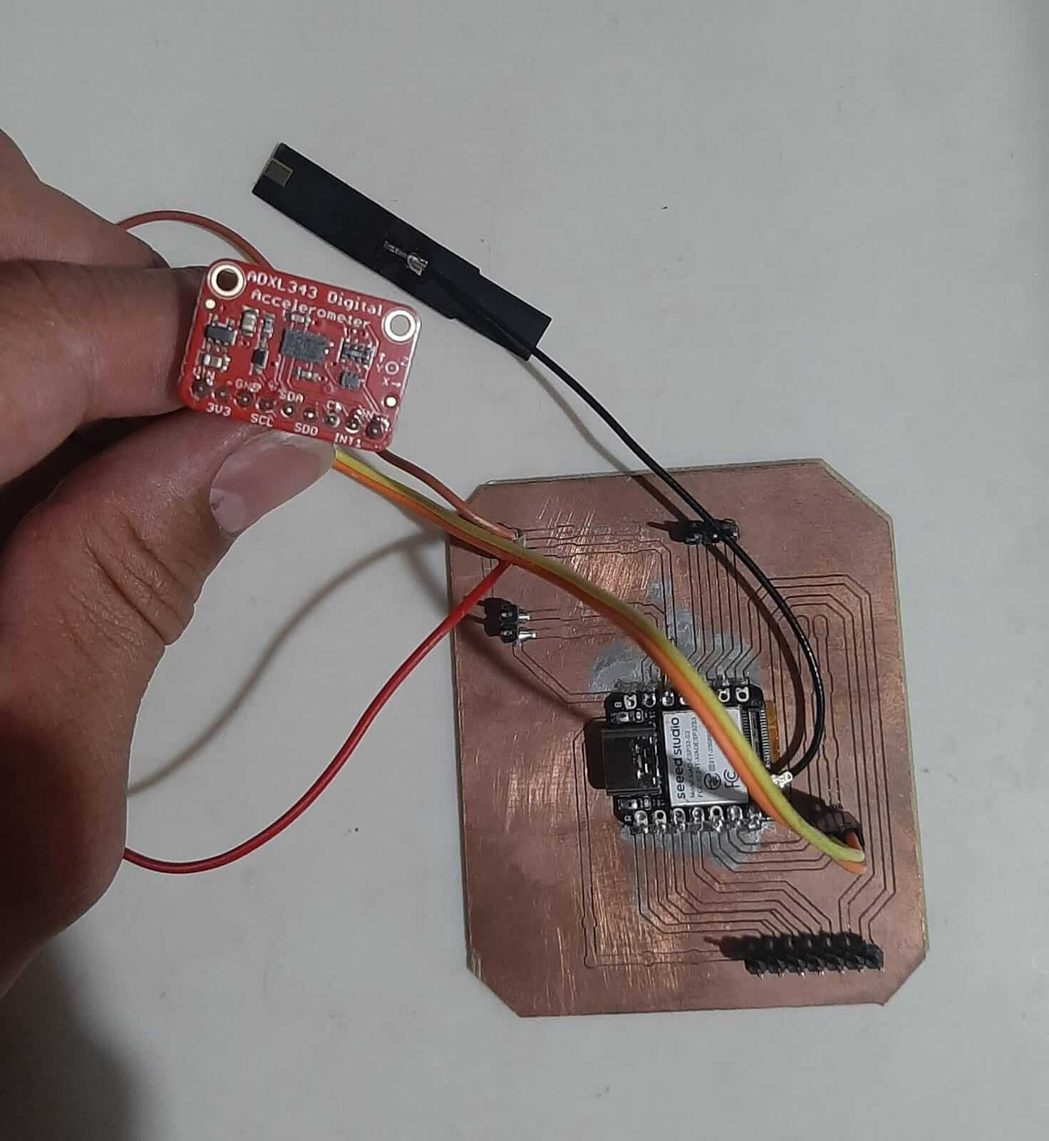
I decided to use the Adafruit IO platform to create an application that interfaces with an accelerometer and displays the data in real-time. The accelerometer is connected to a microcontroller, which sends the data to Adafruit IO using MQTT protocol. The application allows users to visualize the accelerometer data in real-time.
The board used for this project is the ESP32, which is a low-cost, low-power system on a chip (SoC) with integrated Wi-Fi and dual-mode Bluetooth. The base project I used for this assignment is the same as the one used in the week 11 assignment, which involves using an accelerometer. The accelerometer used is the ADXL345, which is a small, thin, low-power, 3-axis accelerometer with high resolution (13-bit) measurement at up to ±16g. The ADXL345 is capable of measuring both static acceleration (e.g., gravity) and dynamic acceleration (e.g., motion or vibration).
The link for the base project is here: INPUT DEVICES WEEK.
The code used for this project is based on the example provided by Adafruit for the ADXL345 accelerometer. The code initializes the accelerometer, reads the data, and sends it to Adafruit IO using MQTT protocol. The code also includes a simple user interface that displays the accelerometer data in real-time.
                        #include "Wire.h"
                        #include "Adafruit_Sensor.h"
                        #include "Adafruit_ADXL343.h"
                        #include "WiFi.h"
                        #include "Adafruit_MQTT.h"
                        #include "AdafruitIO_WiFi.h"

                        #define IO_USERNAME  "honduway"
                        #define IO_KEY       "aio_zdNG98rhIfvUuHU1KXTUeR9zU3rl"
                        #define WIFI_SSID      "oegr"
                        #define WIFI_PASS      "oegr1234"

                        AdafruitIO_WiFi io(IO_USERNAME, IO_KEY, WIFI_SSID, WIFI_PASS);

                        AdafruitIO_Feed *DATAREADY = io.feed("dataready");
                        AdafruitIO_Feed *X_ = io.feed("x");
                        AdafruitIO_Feed *Y_ = io.feed("y");
                        AdafruitIO_Feed *Z_ = io.feed("z");

                        bool state_=false;

                        #define SDA_PIN 5 // SDA pin for ESP32
                        #define SCL_PIN 6 // SCL pin for ESP32

                        Adafruit_ADXL343 accel1 = Adafruit_ADXL343(12345);

                        void setup(void)
                        {
                        delay(5000);
                        Serial.begin(115200);
                        while (!Serial);

                        WiFi.begin(WIFI_SSID, WIFI_PASS);
                        while (WiFi.status() != WL_CONNECTED) {
                            Serial.print("*");
                            delay(500);
                        }
                        Serial.println("WiFi connected!");

                        Wire.begin(SDA_PIN, SCL_PIN); // Initialize I2C with custom SDA and SCL pins

                        // I2C Scanner
                        Serial.println("Scanning for I2C devices...");
                        byte count = 0;
                        for (byte address = 1; address < 127; address++) {
                            Wire.beginTransmission(address);
                            if (Wire.endTransmission() == 0) {
                            Serial.print("Found I2C device at address 0x");
                            if (address < 16) Serial.print("0");
                            Serial.println(address, HEX);
                            count++;
                            }
                        }
                        if (count == 0) {
                            Serial.println("No I2C devices found.");
                        } else {
                            Serial.print("Found ");
                            Serial.print(count);
                            Serial.println(" I2C devices.");
                        }
                        Serial.println("");

                        /* Initialise the first sensors, this uses the default address */
                        if(!accel1.begin(0x53))
                        {
                            /* There was a problem detecting the ADXL343 ... check your connections */
                            Serial.println("Ooops, no ADXL343 nr1 detected ... Check your wiring!");
                            while(1);
                        }

                        /* Set the range and data rate to whatever is appropriate for your project */
                        /* See the sensortest example for more details */
                        accel1.setRange(ADXL343_RANGE_2_G);

                        accel1.setDataRate(ADXL343_DATARATE_1600_HZ);

                        /* Display some basic information on these sensors */
                        accel1.printSensorDetails();
                        Serial.println("");
                        Serial.print("Connecting to Adafruit IO DASHBOARD");
                        io.connect();

                        // Wait for connection
                        while(io.status() < AIO_CONNECTED) {
                            Serial.print(".");
                            delay(500);
                        }
                        state_=true;
                        io.run();
                        DATAREADY->save(state_);
                        delay(3000);
                        }

                        void loop(void)
                        {
                        /* Get new sensor events */
                        sensors_event_t event1;
                        accel1.getEvent(&event1);

                        /* Display the results (acceleration is measured in m/s^2) */
                        Serial.print("X: ");Serial.print(event1.acceleration.x); Serial.print(", ");
                        Serial.print("Y: ");Serial.print(event1.acceleration.y); Serial.print(", ");
                        Serial.print("Z: ");Serial.print(event1.acceleration.z); Serial.println(".");

                        io.run();
                        X_->save(event1.acceleration.x);
                        Y_->save(event1.acceleration.y);
                        Z_->save(event1.acceleration.z);
                        delay(5000);
                        }
Code source: Github Repository
The changes made to the code are:
- Added the Adafruit IO library to connect to the Adafruit IO platform.
- Created feeds for the accelerometer data (X, Y, Z) and a feed for the data ready state.
- Modified the loop function to send the accelerometer data to Adafruit IO.
- Added a delay of 5 seconds between readings to avoid flooding the server with data.
- Added a state variable to indicate when the data is ready to be sent.
- Added a function to connect to the Adafruit IO platform and send the data.
The application allows users to visualize the accelerometer data in real-time and provides a simple user interface for interacting with the device. The data is sent to Adafruit IO using MQTT protocol, which allows for real-time updates and easy integration with other IoT devices.
This was the esp32 part of the project, the other part is the Adafruit IO platform. The Adafruit IO platform provides a user-friendly interface for visualizing the accelerometer data and allows users to create custom dashboards and widgets.
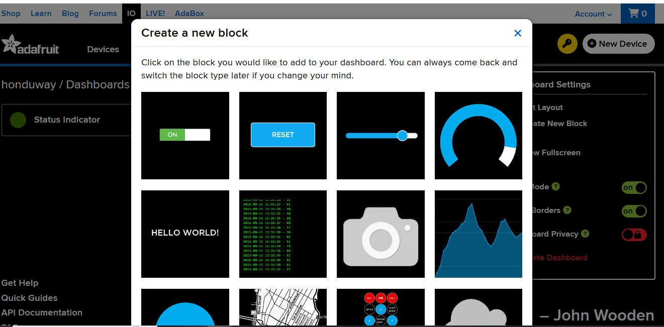
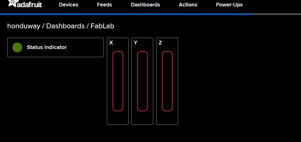
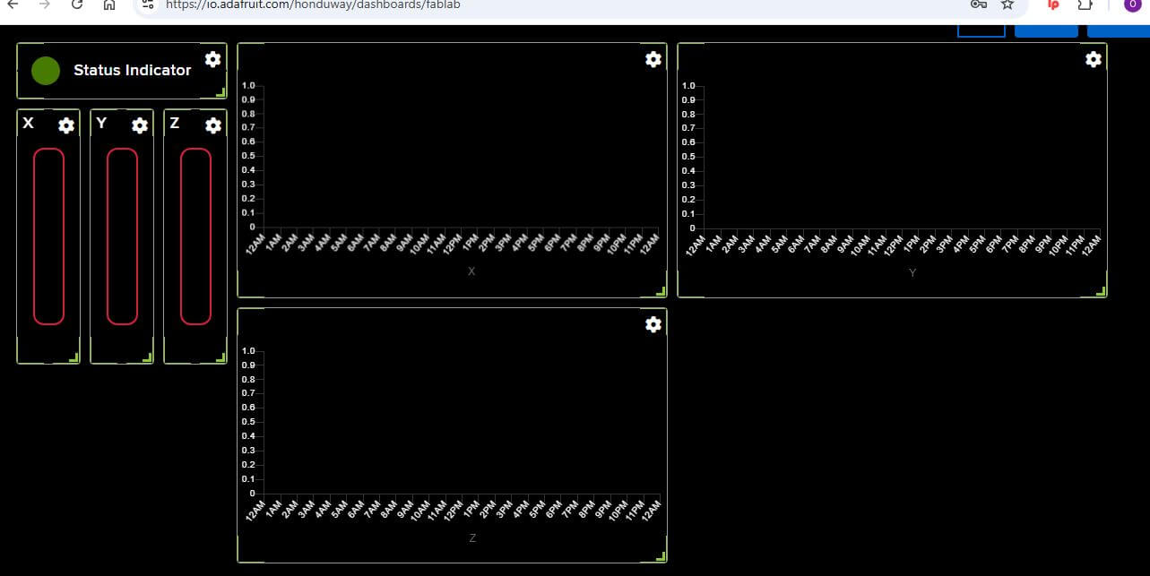
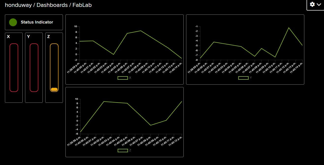
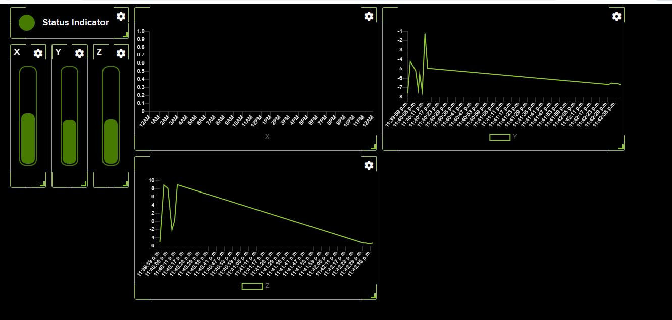
I added some bars to the dashboard to visualize the accelerometer data in real-time. The bars change color based on the value of the accelerometer data, making it easy to see when the device is moving. Also, I added some graphs to visualize the accelerometer data over time. The graphs show the X, Y, and Z values of the accelerometer data in real-time and the history of the data.
To connect the ESP32 to the Adafruit IO platform, I used the MQTT protocol. Also, I needed to create feeds for the accelerometer data (X, Y, Z) and a feed for the data ready state. The feeds are used to send the accelerometer data to the Adafruit IO platform and to receive the data from the platform. This allows the application to display the accelerometer data in real-time and to visualize the data over time.
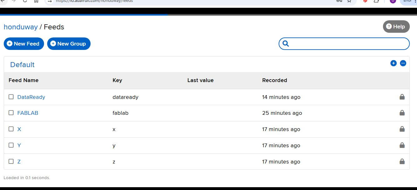
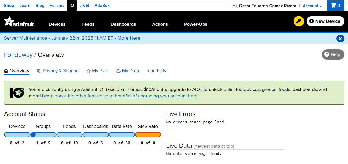
Something important to mentions is that Adafruit IO create an specific ID and key for each dashboard, this is critical to ensure the firmware can connect to the dashboard and send the data. The ID and key are used to authenticate the device with the Adafruit IO platform and to ensure that the data is sent to the correct dashboard.
Ones everything is set up, the application can be used to visualize the accelerometer data in real-time. The next images show the application in action, with the accelerometer data being displayed.
Issues
The main issue I encountered during this week was the low rate of data transmission Adafruit IO allows for free accounts. The free account allows only 30 messages per minute, which is not enough for real-time applications. This limitation made it difficult to visualize the accelerometer data in real-time and to create a responsive user interface.
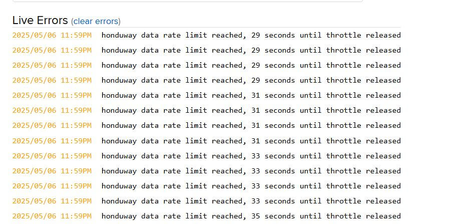
The image above shows the error message I received when trying to send more than 30 messages per minute. This limitation is a significant drawback of the Adafruit IO platform and may require users to upgrade to a paid plan for more advanced features. However, the platform is still useful for simple applications and for users who are new to IoT development.
To avoid this issue, I just added a delay of 5 seconds between readings to avoid flooding the server with data. This allowed me to visualize the accelerometer data in real-time without exceeding the message limit.
Here some videos of the application in action:
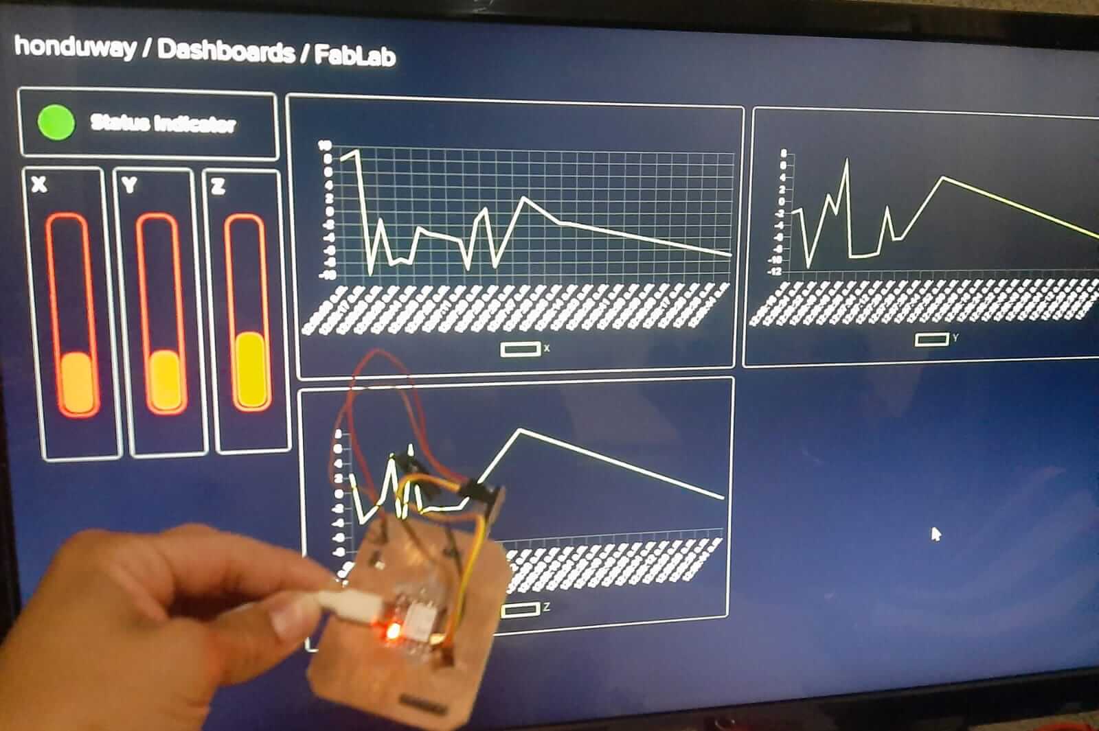
HERO SHOT
Project Files links
In the next links, you can download the files for the assignments.
Conclusion
In conclusion, this week was focused on interface and application programming, with a particular emphasis on comparing different tools and creating an application that interfaces with an input device. The group assignment involved researching and analyzing different tools for interface and application programming, while the individual assignment involved creating an application that interfaces with an accelerometer and displays the data in real-time.
Lessons Learned
- The importance of choosing the right tool for the job.
- The challenges of real-time data transmission and the limitations of free accounts on cloud platforms.
- The benefits of using cloud-based platforms for IoT applications.
- The importance of understanding the strengths and weaknesses of different tools and platforms.
- The importance of testing and debugging applications to ensure they work as intended.
- The importance of creating a user-friendly interface for applications.
- The importance of understanding the limitations of the tools and platforms used.
- The importance of creating a responsive user interface for applications.
Resources
- Adafruit IO: Adafruit IO
- Adafruit ADXL345: Adafruit ADXL345
- ESP32: ESP32
- MQTT Protocol: MQTT Protocol