Week 10, Output Devices
Table of Contents
- Overview
- Resources
- Group Assignment
- Final Version
- PCB Design
- Milling/Soldering
- Coding/Testing
- Files
Overview
You'll find me designing the PCB I'll be using in my final project. This PCB will be connected to the robot.
Resources
- I got help from ChatGPT while trying to design the connection from the VL53L1X to the XIAO ESP32C6.
- I got help from ChatGPT while learning how to write code to turn a continuous servo.
- I used Kicad to design my PCB.
- I used a SRM-20 to mill my PCB.
- I used Arduino IDE to write code.
- I used Inkscape to help with getting the milling toolpath ready.
- I used Mods to create the milling toolpath.
Group Assignment
Here is the group assignment.
Final Version
PCB Design
Parts:
- 2 Continuous Servo Motors (MG 996R)
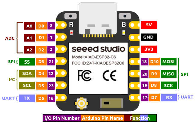
- 1 XIAO ESP32C6
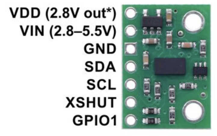
- 1 VL53L1X
- 1 Polarized Capacitor (EEE-FN1E101UL)
In the PCB, there will be 3 horizontal pin headers for each of the servos.
XIAO ESP32C6 pins:
Pins of the VL53L1X breakout board:
I imported the components and connected them as needed.
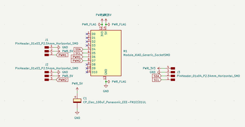
I positioned the components and ran a DRC.
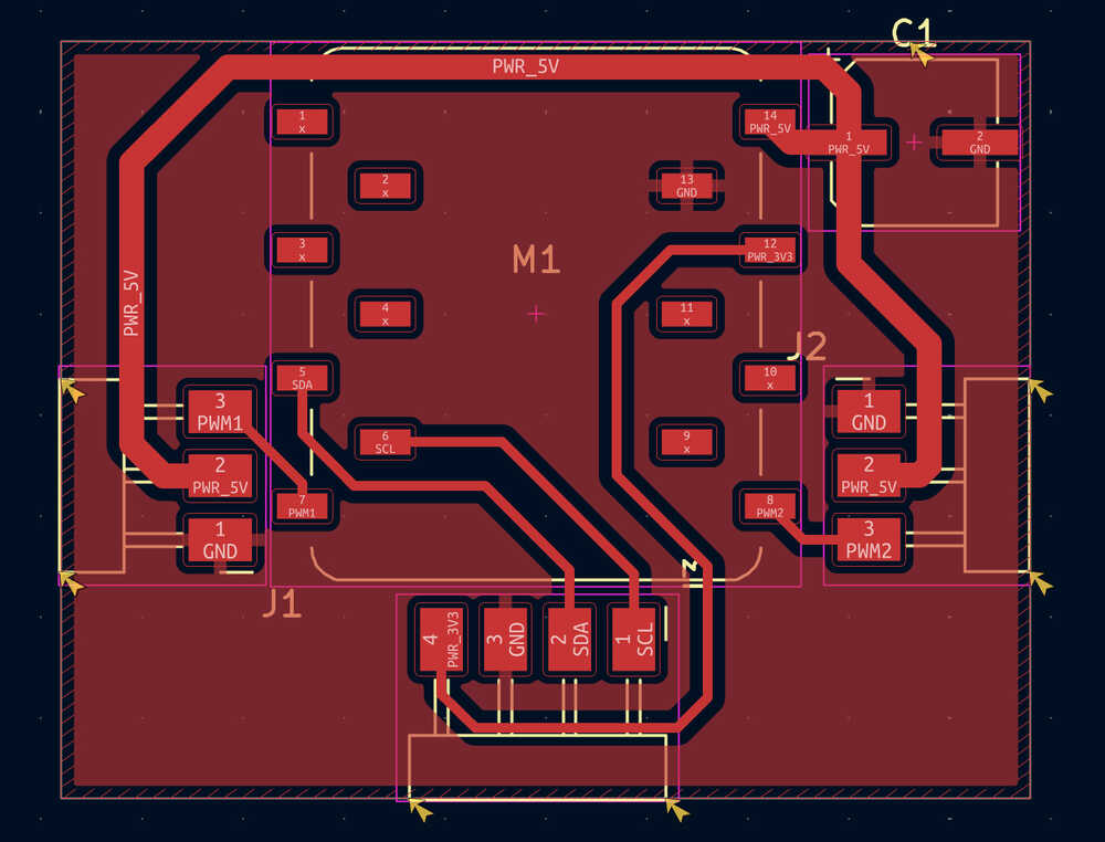
Except some warnings, there wasn't anything bad. The warnings aren't important, so the design of this PCB is done!
Milling/Soldering
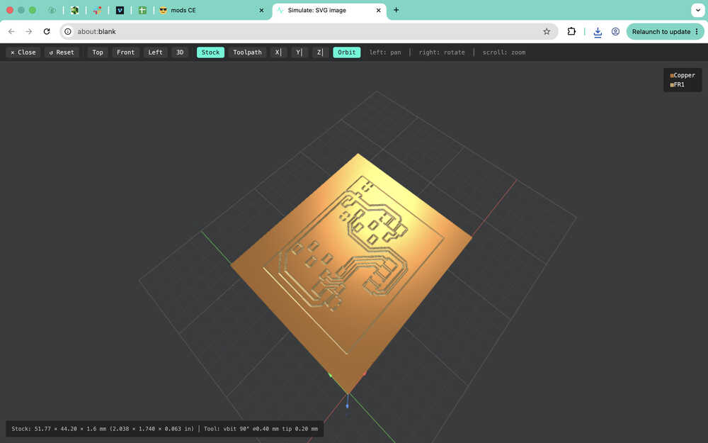
I'll be using Mods when creating the toolpath of this PCB. You can find the process at which I created the toolpath in my week 8 assignment. However, this time, I didn't change the setting in the Home section of Mods since that created a problem at that time (week 8).
The F.Cu layer:
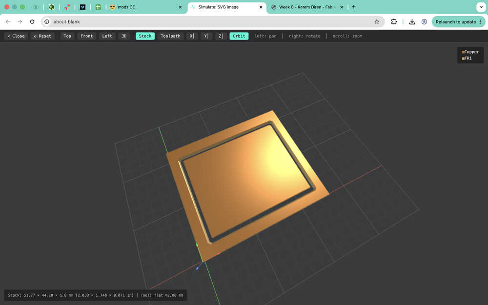
The Edge.Cuts layer:
I preapared the copper clad.
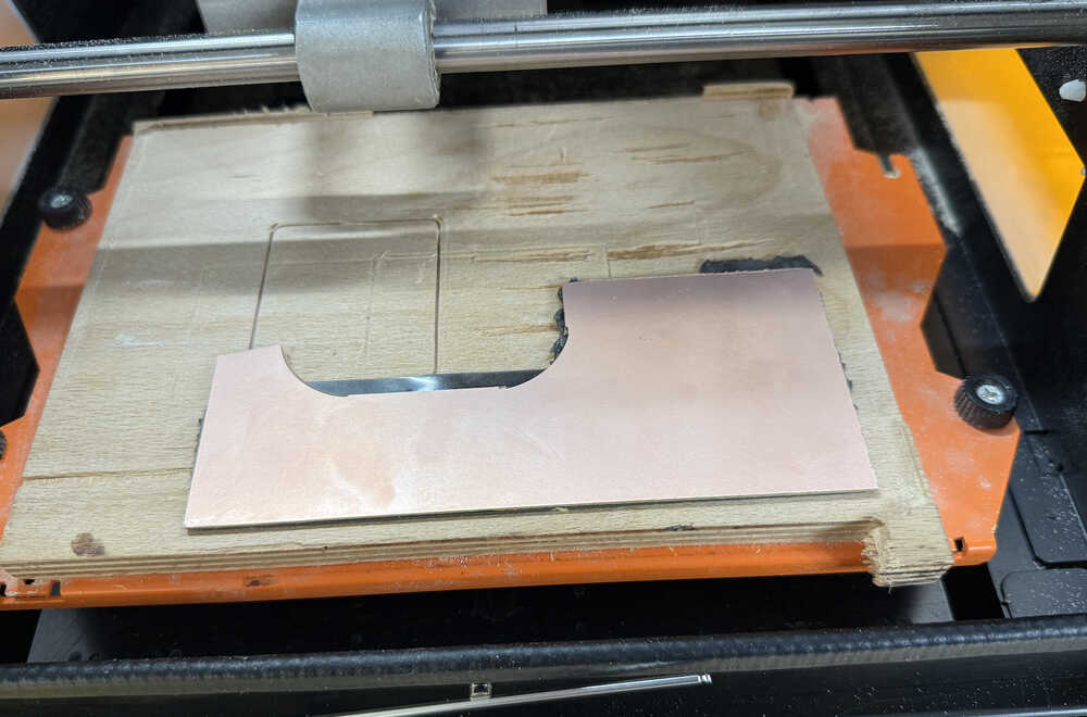
I preapared the machine.
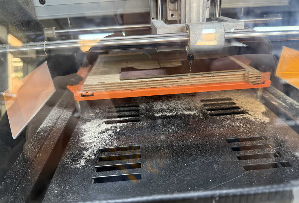
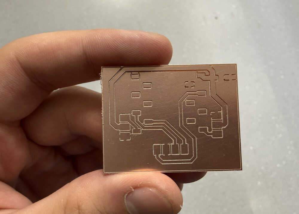
The PCB is cut.
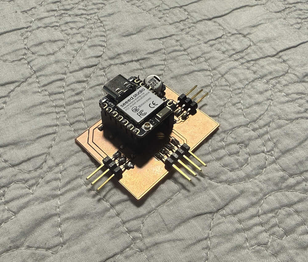
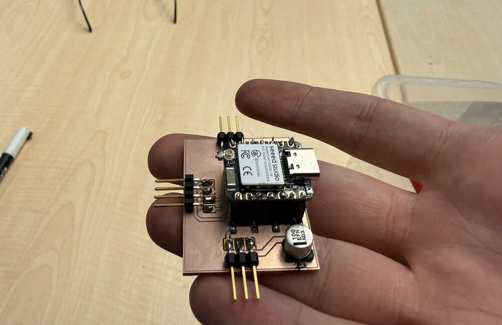
I soldered the parts.
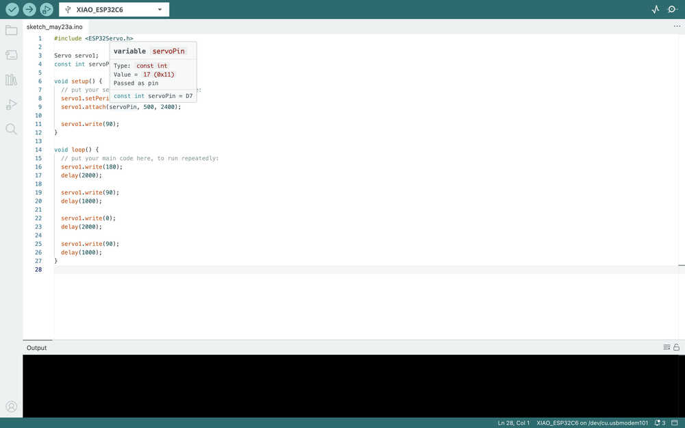
Coding/Testing
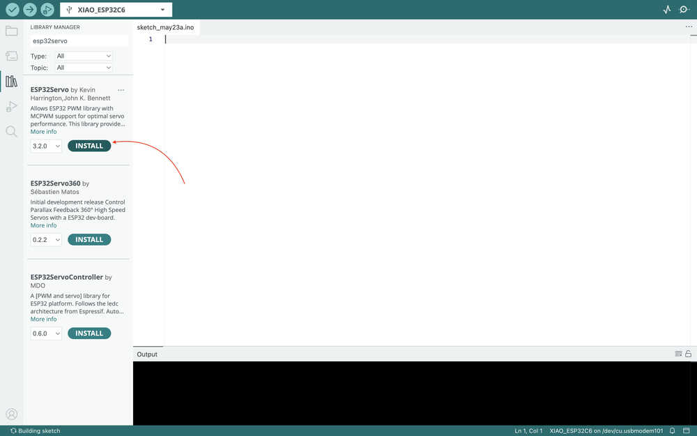
I started by downloading this library in Arduino IDE.
I got this code from ChatGPT, which is for making a continuous servo turn.
The servo is turning:
Files
Here are the files.