Carrier-Bot | Thoughts
!!This is my previous final project idea. I changed my project idea after Update 3 in this site. You can find my current final project in Update 3!!
Project Idea
I want to make a robot that can carry items. The robot can carry items by the user putting their items onto a platform. The robot carries its items to a pinged location. The robot will be pinged by a phone or a portable button. I want the length of the robot to be customizable according to the needs of the user. The robot will have wheels resembling a tank's. I want the robot to have an auto-navigation function (make it so it can find its own way to the ping). I will probably use an ultrasonic sensor to navigate around obstacles. Maybe play a ding sound after completing task (reaching pinged location).
Some Ideas for navigation:
- The robot will store the direction of the pinged place and find its way there by using sensors etc. The robot will have dc motors for this idea.
- A camera system to find the target. The robot will find its way to the target using the location data from the camera. The robot will have stepper motors for this idea.
- A camera the user carries (or is being carried another way), that always looks down, detects the distance the user walked. The robot (with stepper motors) goes to the calculated location. Example: The camera detects four colors at four (or three etc.) points of the taken picture; after like a second, it retakes the picture, looks for the four colors with the same distances to each other; when found, calculate the distance from their first position to get distance moved.
Key Features:
- Can be pinged by a device
- Finds its way to the pinged place
- Can carry items
- Can change its length
- Plays a sound after completing its task
Draft Materials List:
- Ultrasonic sensor
- DC/Stepper motors
- PCB (motor driver, capacitor, resistor etc.)
- A portable power source (probably some batteries)
- 3D printed parts
- Something to play sound with
- A camera
Sketch:
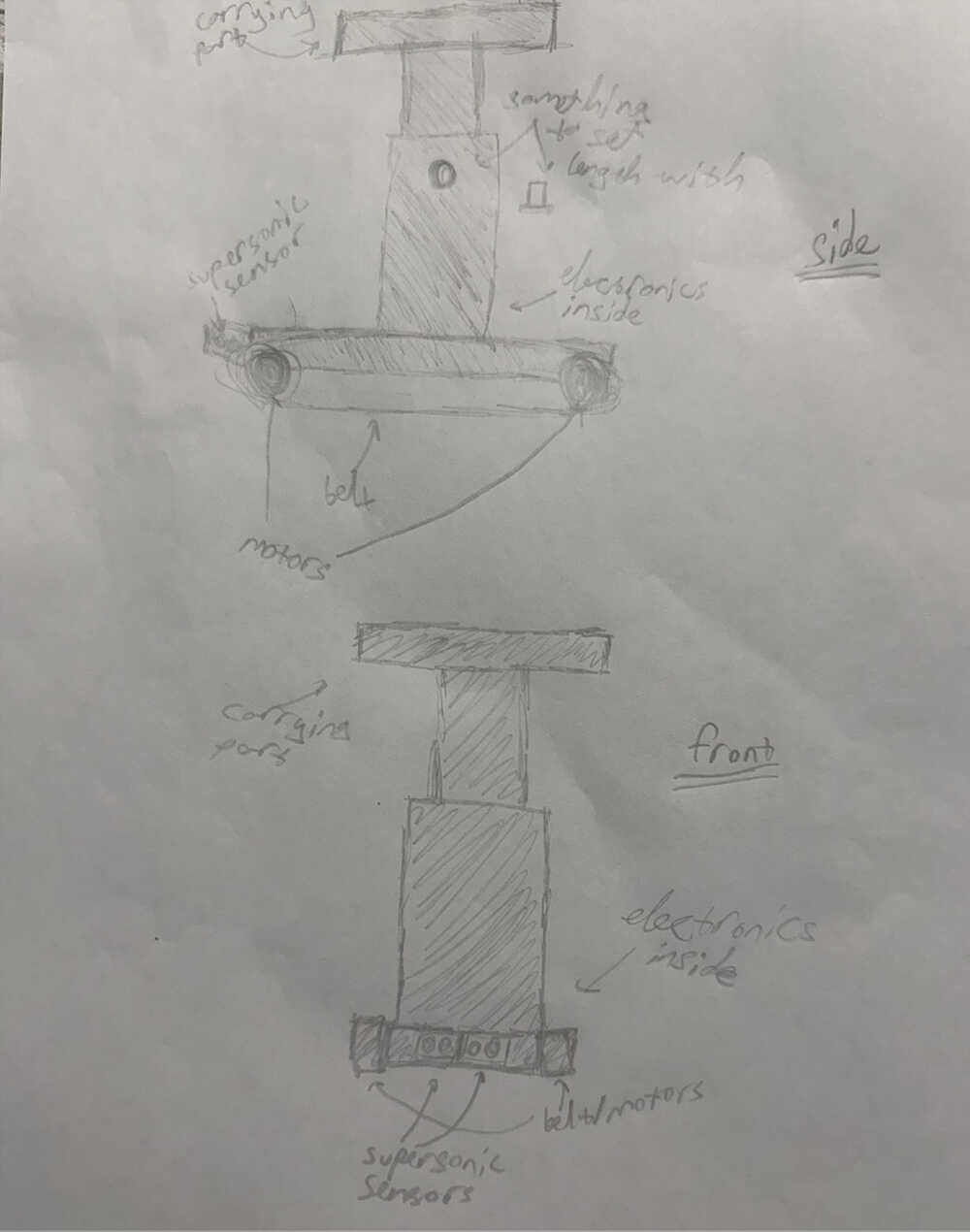
Motivation
People forget things. People forget to take their items with them when changing locations if they're working on a project, talking on the phone, watching/listening to media, or thinking. After realizing you forgot your items, trying to find them on top of your busy day feels like a great hassle. This project is here so that you can get to your items immediately, without having to feel the dread of trying to find or remember them.
The second reason for me to design this is so that you don't have to carry your items. This isn't the first reason even though it's in the name because, if I really wanted the bot to just carry items, I would've just designed a platform with wheels that you can tie to your hand with a string. The main idea of this project is that you don't have to touch or think about your items to have them with you. Just click the button when you need them, and they're next to you.
Carrier-Bot | Basic Component Creating | Update 1
Info About the Update
I wrote a program that'll help the robot find its way to the goal location. You can find the code here and some example outputs here. I also created an electronic design from Kicad and a really basic (it doesn't have all of the functions I'm planning to implement) 3D model of the robot. Also, because of how I've written the code, I'm planning on using four ultrasonic sensors, each directed to different directions, to navigate the bot. The current code can only simulate the movement of the bot in digital space (as in, it can only show what path it'll take in different situations); however, if the code is successful in real life, I'm basically done with the code of the navigation part since it's not that hard to implement code for electronic parts into my code. I currently have no idea on how to do communication between parts. I got some feedback, however, on how to locate the goal location. A relative of mine recommended using GPRS. Currently, I literally have almost no idea how I can use a GPRS, how it operates, or if it would be even applicable in this situation. I'm planning on looking into it before I post the second update of my final project, so you will probably be able to see my decision on using it in the second update.
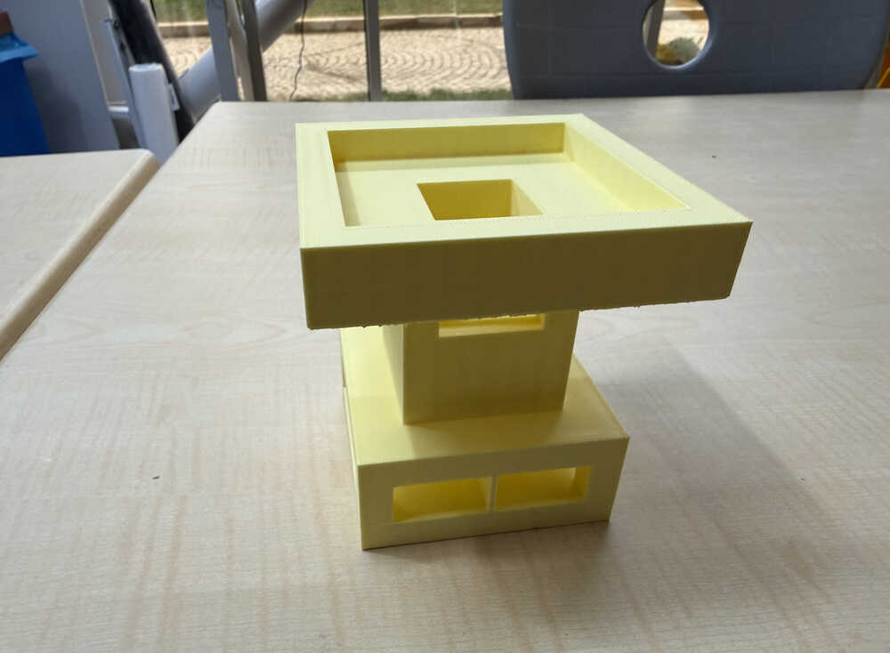
3D Design
This design is smaller than how its actual size will be. I didn't implement the changeable length and sound playing functions in this prototype; although, I might discard the sound playing function idea altogether.
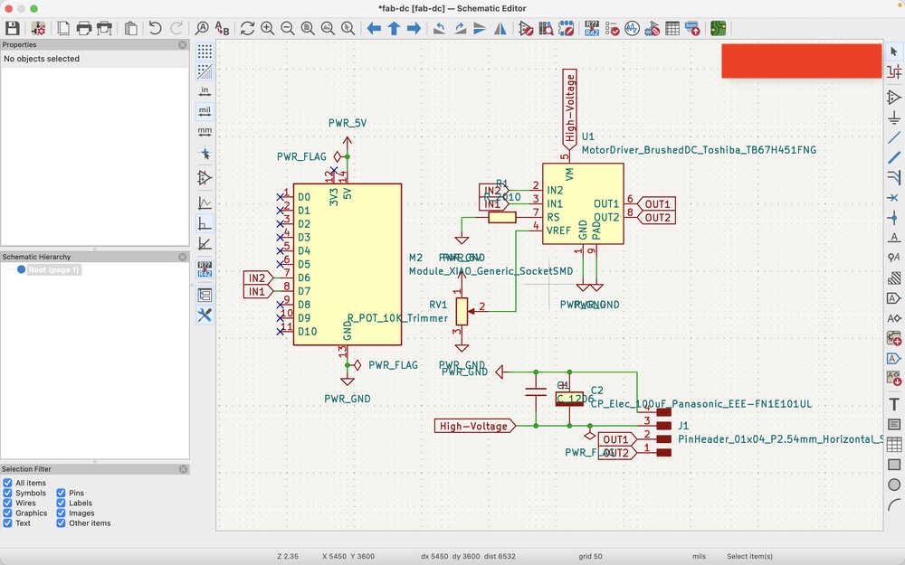
Electronics Design
I created a simple PCB design for using DC motors.
Carrier-Bot | Researching | Update 2
Info About the Update
This update is for doing some research and deciding what parts to use exactly. This update doesn't contain my final thoughts, but the information below is basically what I have decided to use currently.
Table of Contents
- Resources
- Goal Locating
- Which Distance Sensor
- Measuring Distance Taken
- Omnidirectional Wheels
- Materials to be Used for the Robot Body
Resources
Asked ChatGPT and used information from the week 11 meet for goal locating.
Used this and this website, and asked ChatGPT for deciding on a distance sensor.
I asked ChatGPT and looked at this website to make a decision on which distance sensor to use.
Goal Locating
I took some names from the week 11 meet and ChatGPT. These devices are nRF24L01+, LoRa (Meshtastic), UWB, RTK GPS, GPRS, and GPS. I asked about the devices to ChatGPT. Basically, it told that UWB was the best among these since it had an appropriate range for my project, it gave both distance and direction, and it was accurate enough for my project.
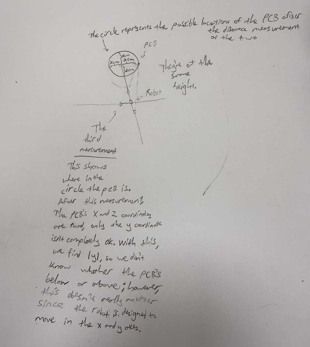
Locating
I'll be using the servo motor to change the position of the UWB module in the robot. Since I'm using only two UWB modules, I'm planning on first taking the distance from the other PCB to the robot PCB when the servo is at 0 degrees, then when it's at 120 degrees, then when it's at 240 degrees (depending on the servo we have, I might do it at 0 - 90 - 180 degrees etc.). Then, I'll do some calculations to find the direction of the other PCB according to the PCB in the robot.
How the locating works:
Which Distance Sensor
I was recommended to test VL53L1X as a distance sensor in the output devices week by Mr. Krisjanis Rijnieks. I wanted to see if I would be able to use this for my final project, too. However, after researching these two from this and this website, and asking ChatGPT, I decided to use HC-SR04 for my final project. Although, I still want to test VL53L1X in the output devices week if I'm not too short in time.
Mini Update
After testing it, I changed my mind on using HC-SR04. At some angles, the sensor gave me 2500cm, so I kind of lost trust. I mean, since I don't want my robot to crash into an angled wall, I feel safer using VL53L1X.
Measuring Distance Taken
I was told a stepper motor was too heavy for mobile devices and was recommended to use a DC motor gear encoder by Mr. Eduardo Chamorro. I asked ChatGPT and looked at this website, and this option seemed good for my final project, so I'll use it.
Movement
I was told about omnidirectional wheels, too, by Mr. Eduardo Chamorro. They seem pretty good so I'll just use them if there are some in the lab.
Materials to be Used for the Robot Body
Top (carrying part): I'm not sure what to make this part from. I was planning on making it from wood by getting help from a laser cutter, but was adviced otherwise by Mr. Krisjanis Rijnieks since that would have made the robot too uneven if a heavy object was placed on one end of the carrying part (since wood isn't that heavy). I want the top part ot be detachable from the middle, so I still believe wood isn't too bad of an option (since it's easy to make copies with); however, I still want to think about this part.
Middle: I'll make this part from 3D since it's hard to make it in any other way. The middle part will have holes and will have the ability to change its length.
Bottom: I'm not too sure of what to make the bottom part from. I may just make it from 3D (and make it attached to the middle part), but I also have an idea of making it from a heavier material so that I can make the top part from wood (since a heavier material in any part will help the robot from becoming too uneven). I also have an idea of just making it from 3D and making a bunch of empty spaces inside it, so that I can fill those empty spaces with heavy materials such as metals so that I can solve the unevenness problem while also using 3D to make the middle and the bottom as a single piece.
Carrier-Bot | Deciding | Update 3
Info About the Update
This update is about deciding what to do with my project. Since I don't have much time left, I want to talk about how I want to change my project. Currently, my school stuff is basically finished. I don't have any AP exams left, I don't have any school exams left, I basically don't have any classes left, so, now, I'll be able to work on the weekly assignments and my final project much more freely.
New Idea
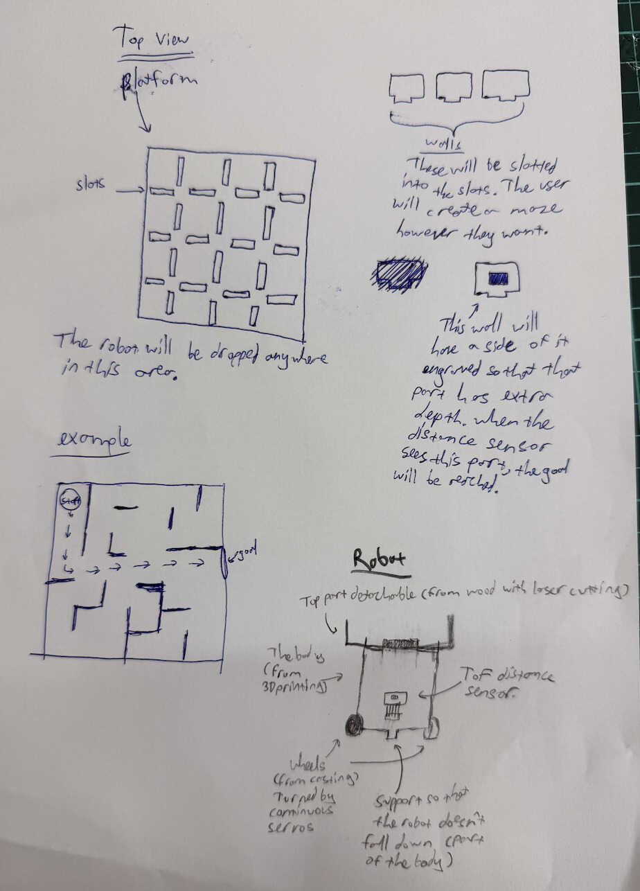
I think of creating a maze that the robot can solve. Basically, there'll be a platform from wood. It'll have holes that'll create a matrix-ish look. I'll also create a bunch of detachable walls that'll basically slot into the holes in the platform. This way, the user can create a maze. The robot will be dropped into somewhere in the maze. It'll find its way to the goal, which will be found by the extra depth one wall will have (which will be created by engraving on the wall). Basically, after scanning the distance between the wall and the robot using a ToF sensor, if the distance is between certain numbers, the robot will have reached the goal.
Current Robot
I'll decrease the robot's size. The robot'll basically be two servos, one ToF distance sensor, and a XIAO ESP32C6. The robot will still be able to carry stuff and the top part will still be made from wood to make it detachable and disposable.
Extras
I will probably connect the robot to the user's computer to make it possible to use different maze solving algorithms with the use of a local site. The default will be the program I wrote, of course, but the other ones may or may not come from different people. If they are indeed made by other people, I'll credit them in the site.
Sketch
Thoughts
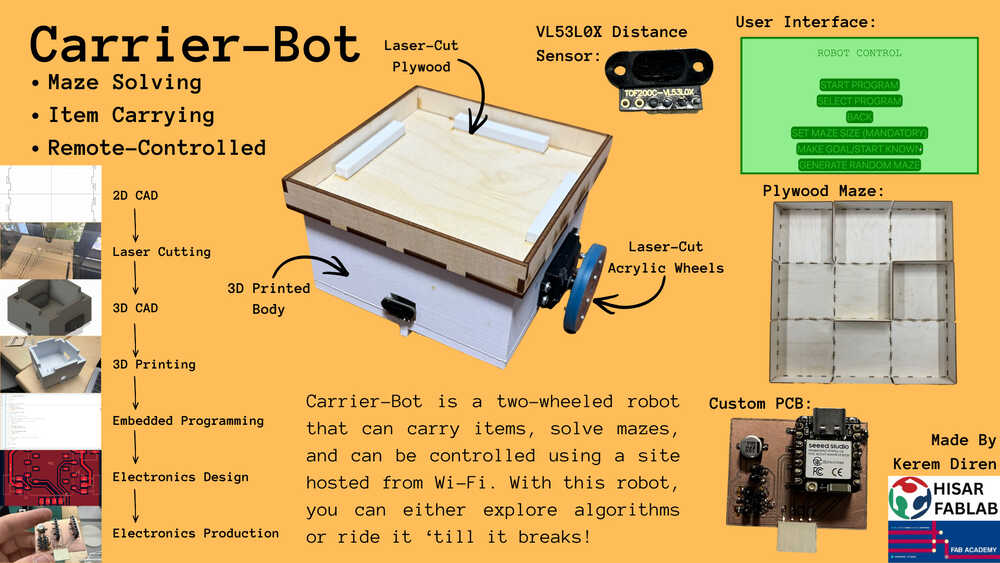
This will help people explore and learn about the algorithms the robot uses. It can also be used to carry items in short distances, too (from one end of a table to the other end etc.). This will be kind of like a mini version of my previous project that is more focused on maze solving and algorithm demonstrating.
Bill of Materials (I'm posting this after finishing my project)
| Item | Quantity | Price (USD) | Price (TL) |
|---|---|---|---|
| Copper clad | ~12cm^2 | ~$0.6 | ~₺27 |
| PLA (filament) | ~200g | ~$4 | ~₺180 |
| 3mm plywood | 1740cm^3 | ~$5 | ~₺225 |
| MG996R servos (with horns) | 2 | $16 | ₺720 |
| M3 bolts | 10 | ~$2 | ~₺90 |
| M3 nuts | 8 | ~$1.5 | ~₺67.5 |
| Polarized capacitor (100uF Panasonic EEE-FN1E101UL) | 1 | $0.5 | ₺22.5 |
| Horizontal pin sockets | 4 | ~$1.5 | ~₺67.5 |
| Vertical pin headers | 8 | ~$1.5 | ~₺67.5 |
| M2 bolts and nuts | 8 | ~$1.5 | ~₺67.5 |
| Vertical pin slots | 14 | ~$2 | ~₺90 |
| XIAO ESP32C6 | 1 | $8 | ₺360 |
| VL53L0X sensor | 1 | $3.11 | ₺140 |
| Powerbank | 1 | $22.3 | ₺1000 |
| Acrylic | ~12cm^3 | ~$1 | ~₺45 |
| Female cable | 1 | $0.5 | ₺22.5 |
| Electrical tape | ~30cm | ~$0.2 | ~₺9 |
| US18650VTC6 batteries | 2 | $13 | ₺585 |
I got this table (and some of the values) from ChatGPT since I didn't know how to make one. Also, I used ₺45 per $1 for price conversion.
Carrier-Bot | Designing | Update 4
Info About the Update
This update is about designing some parts of my final project. I may need to change the designs in future updates since, I mean, something might go wrong after actually testing the parts.
Table of Contents
- PCB Design
- 3D Design
- Top Part Design
- Files
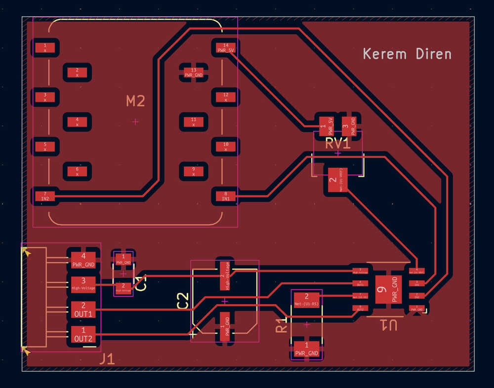
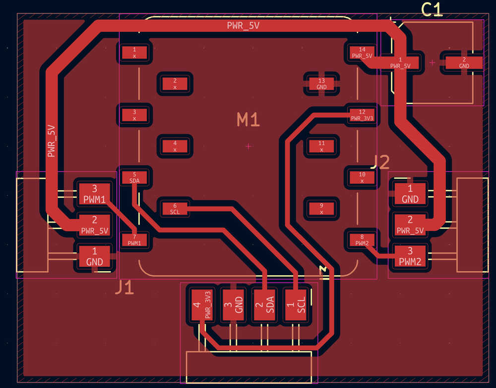
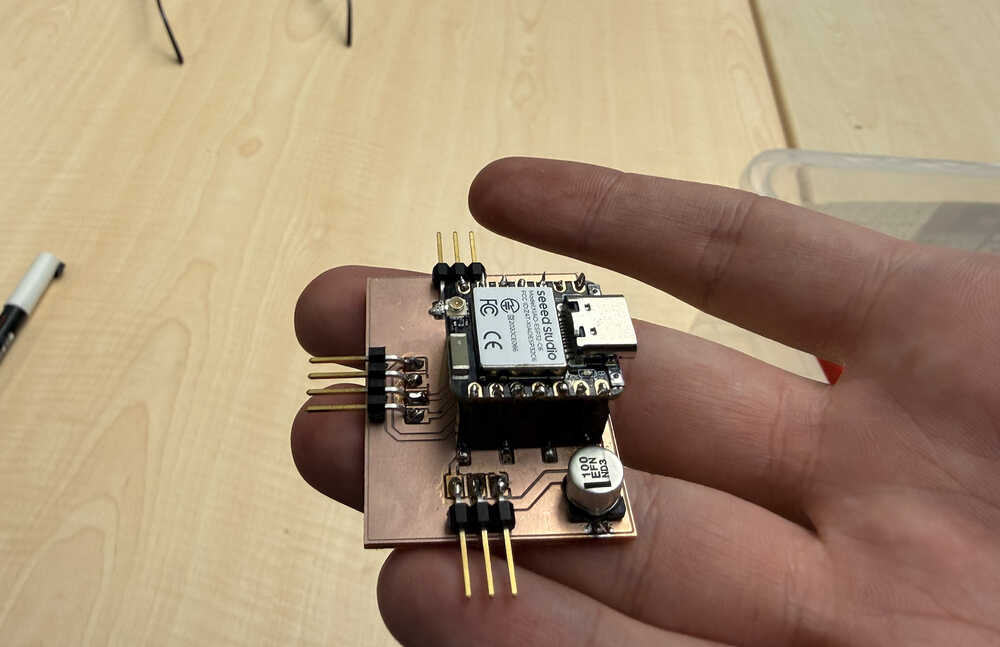
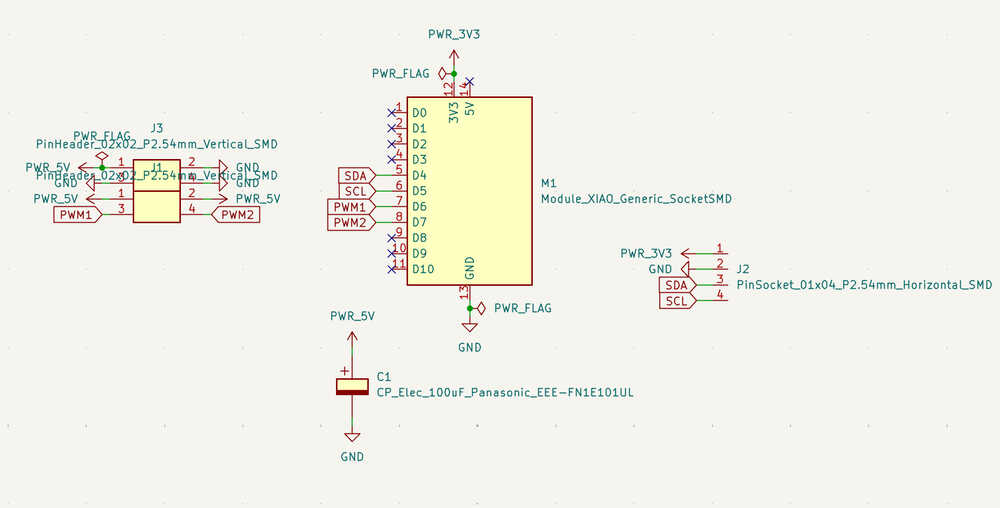
PCB Design
I will design this PCB as my week 10 assignment, so you can find the full documentation there.
Parts:
- 2 Continuous Servo Motors (MG 996R)
- 1 XIAO ESP32C6
- 1 VL53L1X
- 1 Polarized Capacitor (EEE-FN1E101UL)
I wrote that I'd use a DC motors with encoder for my final project robot, but the lab doesn't have them currently, so I'll just use continuous MG 996R servo motors.
This PCB will be in the robot itself.
The continuous servo motors will be on the two sides of the PCB.
The VL53L1X will be a breakout board and I will be making some connection things to the VL53L1X from the PCB.
I'll be using XIAO ESP32C6 for locating.
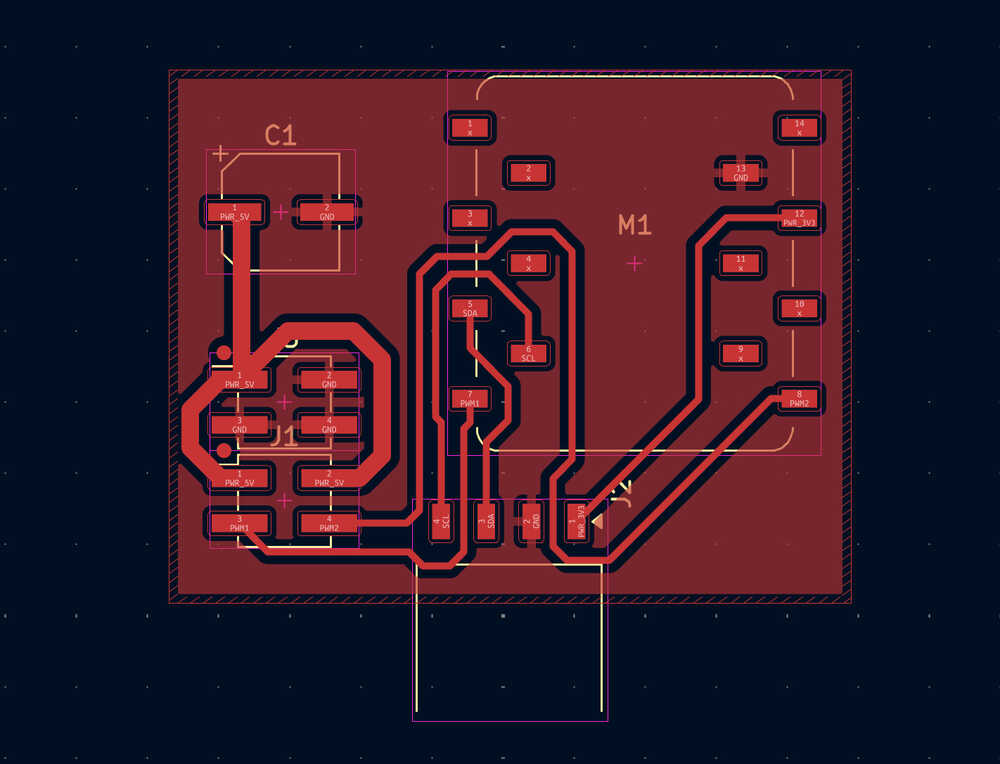
PCB Design:
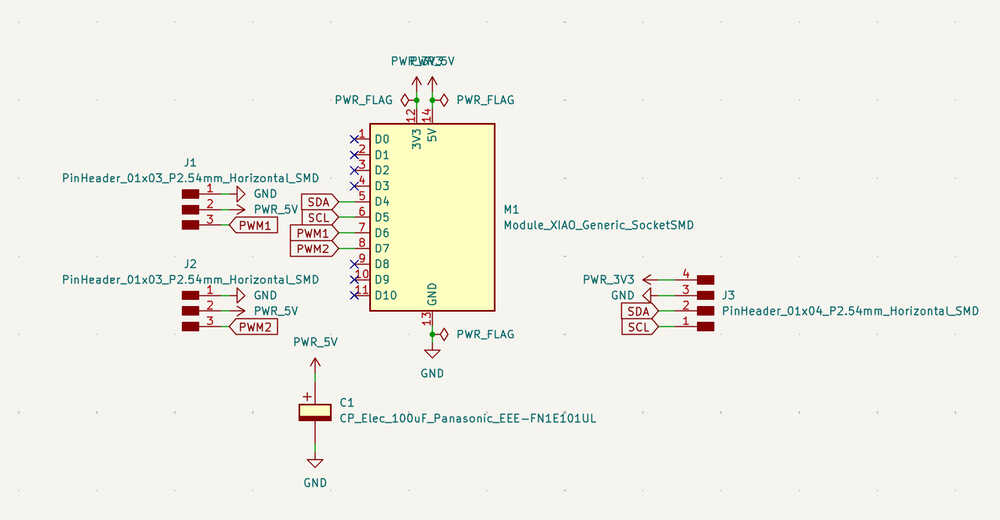
PCB Layout:
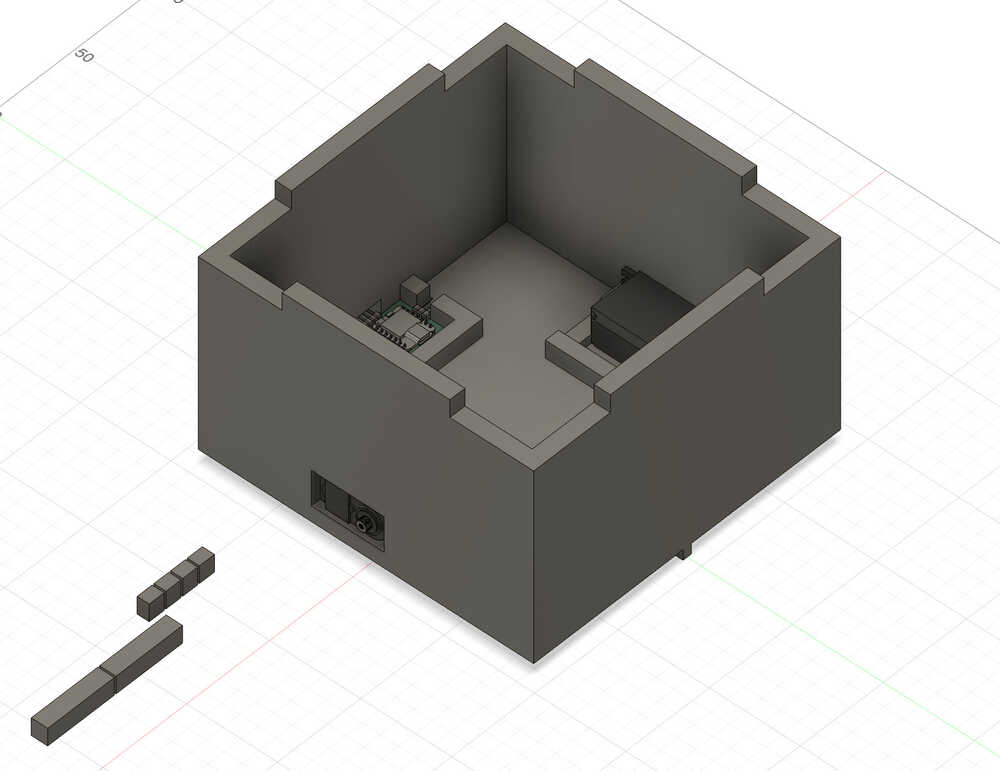
3D Design
The documentation of this part can be found in my week 15 assignment. This is basically how the 3D printed part will be.
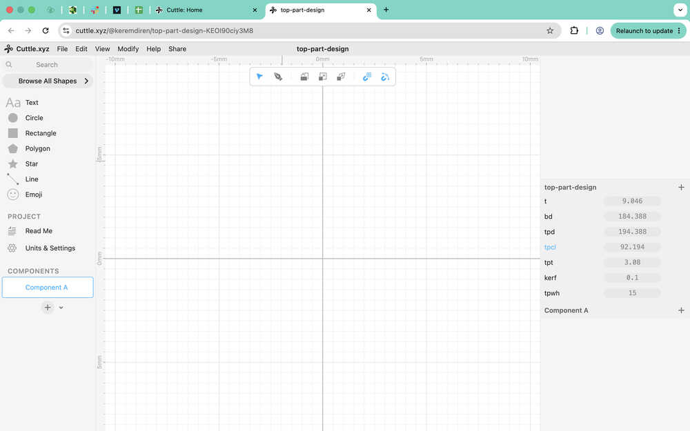
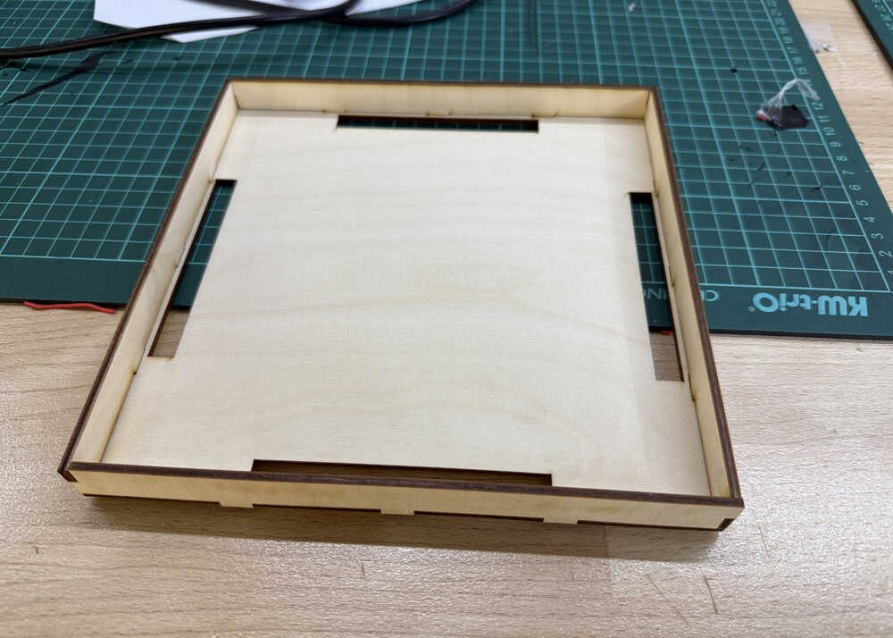
Top Part Design
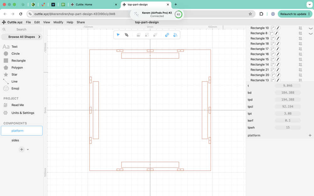
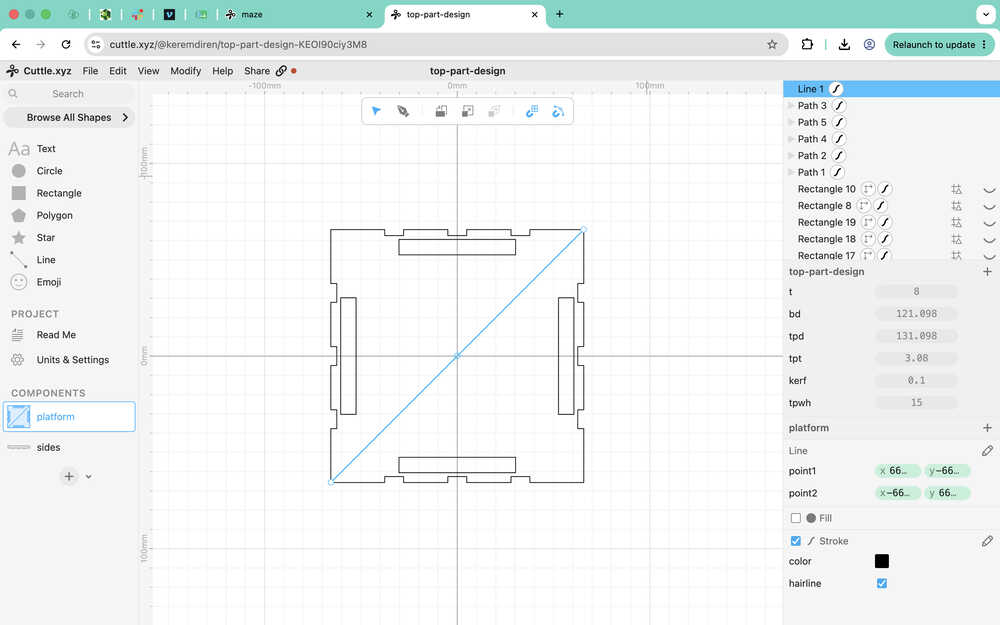
I started by importing some parameters from my 3D design into cuttle. I also added a kerf parameter equal to 0.1mm.
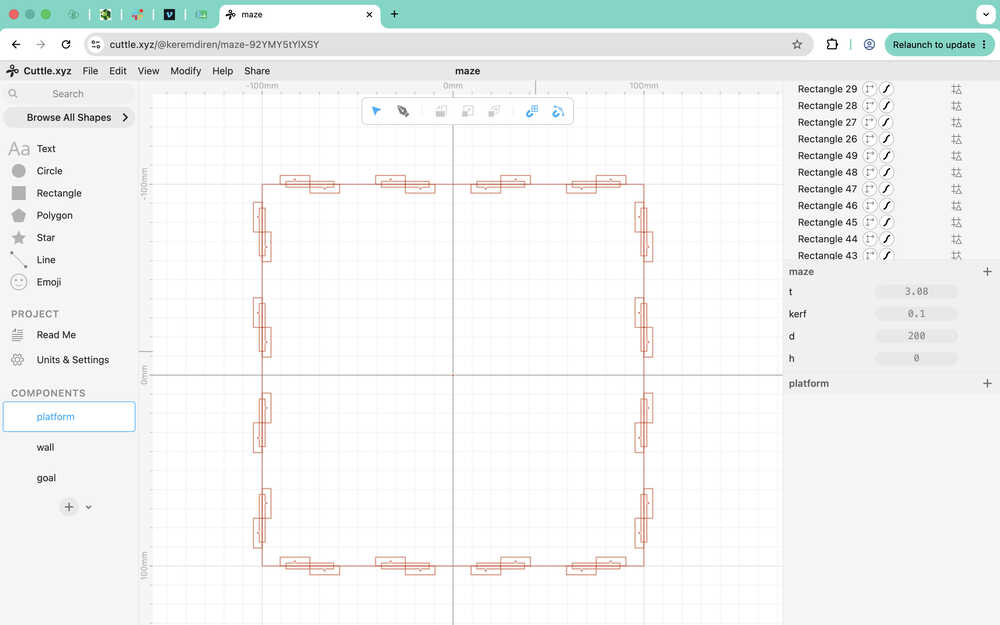
I created some guides. The outer square represents the size of the top platform. The inner square represents the size of the body of the robot. The four rectangles are basically the holes that'll act as the connection to the body of the robot.
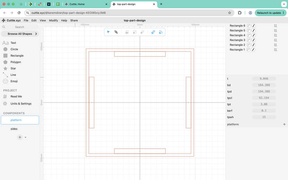
I created some more guides for connecting the platform to the walls of the top part.
Using the pen, I went over the guides.
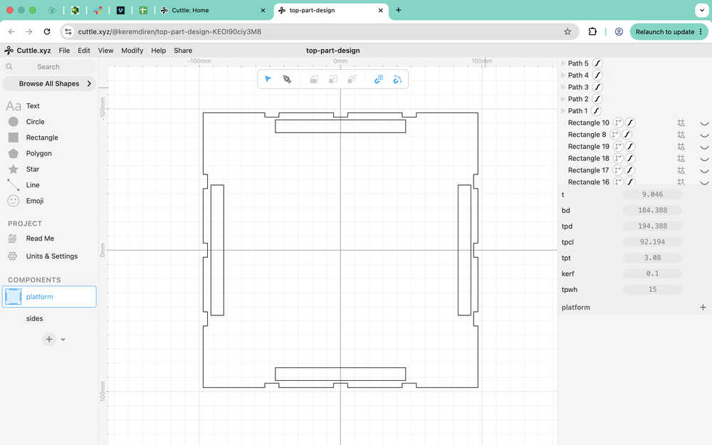
I edited the points to make them parametric.
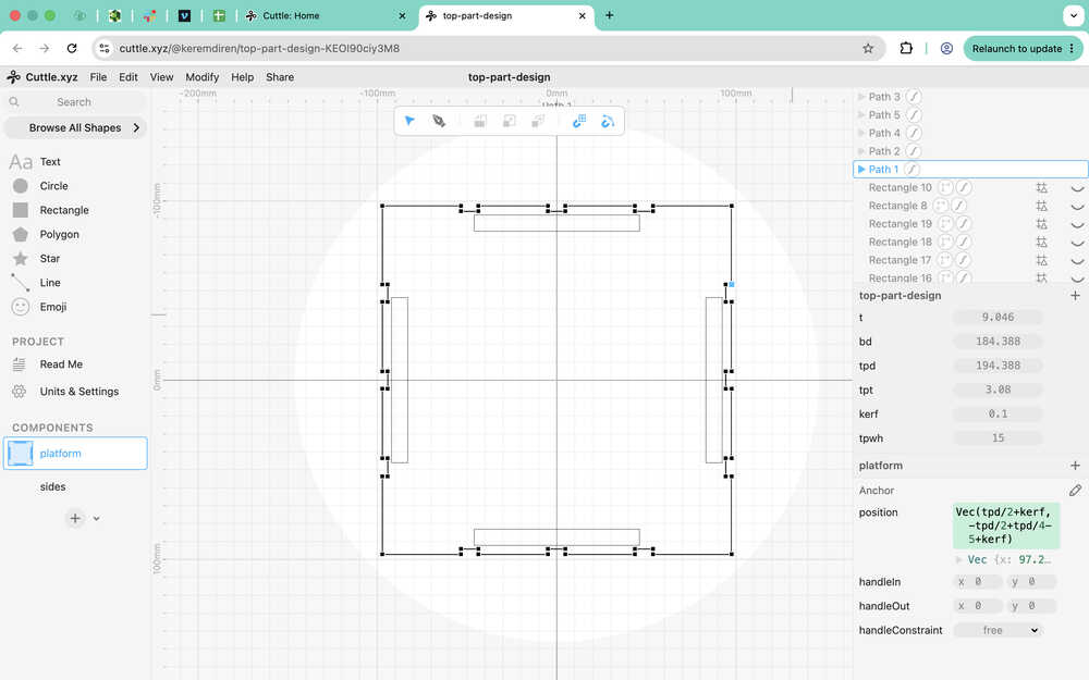
The platform part is done.
I started the wall part by creating some guides.
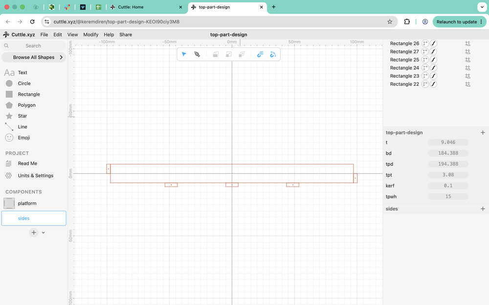
I used the pen to trace the guides and then made the design parametric.
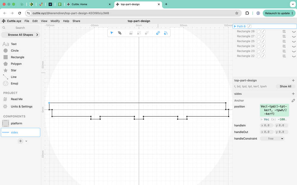
The sides part is finished.
Files
Here are the files.
Here is my Cuttle design.
Carrier-Bot | Part Creating | Update 5
Info About the Update
This update is about me creating the parts I designed previously.
Table of Contents
- Creating PCB
- 3D Print
- Laser Cutting
- Files
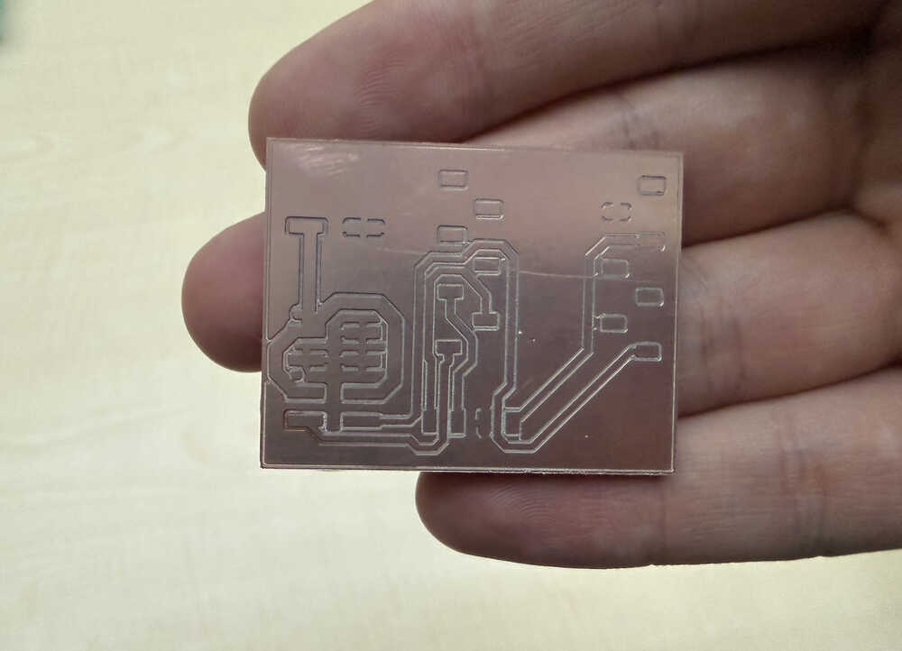
Creating PCB
I'll be using Mods while creating the toolpath of my PCB. You can find the documentation of me creating my PCB in my week 10 assignment.
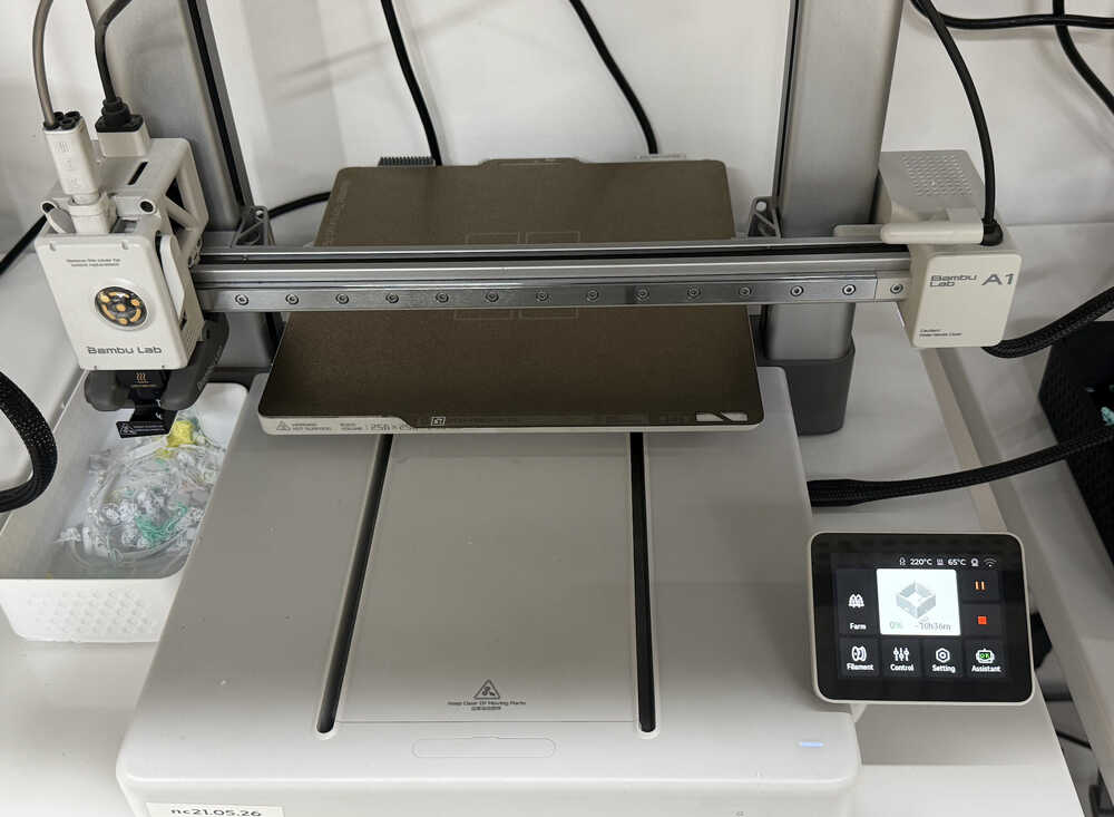
3D Print
I made the toolpath from Bambu Lab using these settings.
I started the printer.
Update
I changed the design a bit in the next update, so the one above isn't the latest version. Although, week 15 has the latest version, too.
Laser Cutting
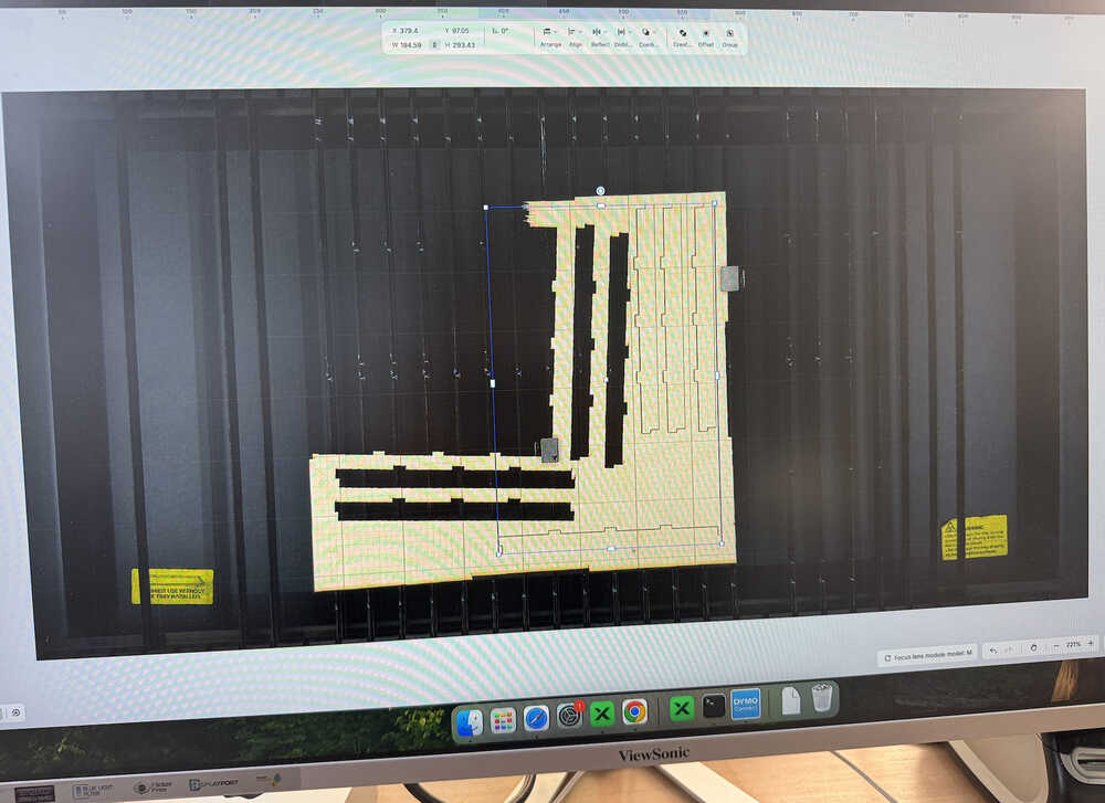
I put the design into the xTool app.
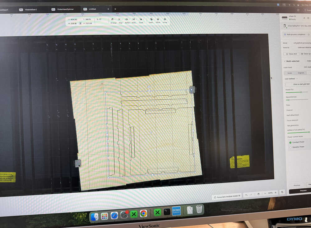
I used 70% power and 30mm/s speed.
The machine is cutting.
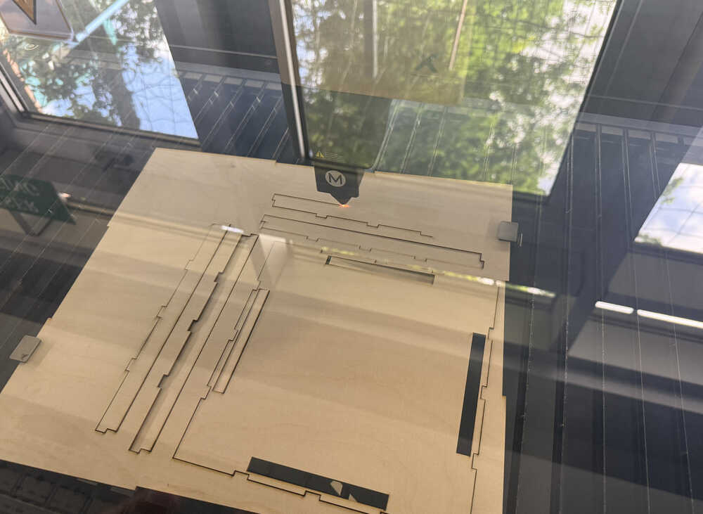
The parts are out.
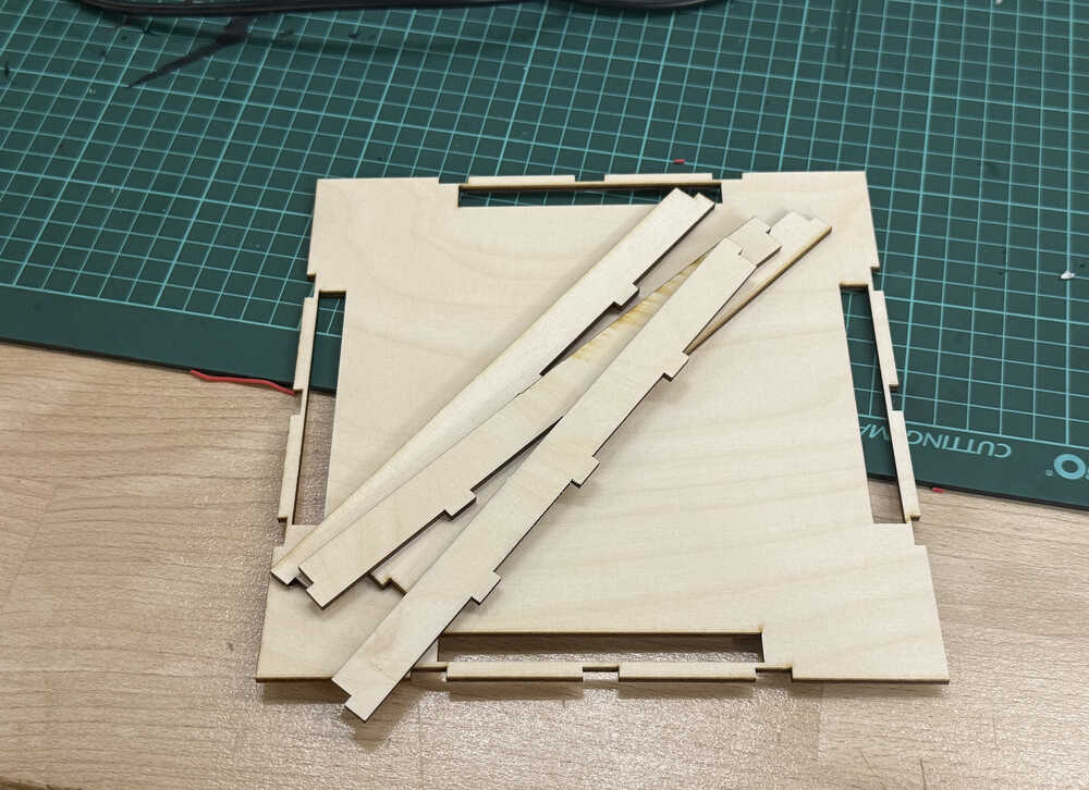
The side parts don't fit into each other since I designed them wrong.
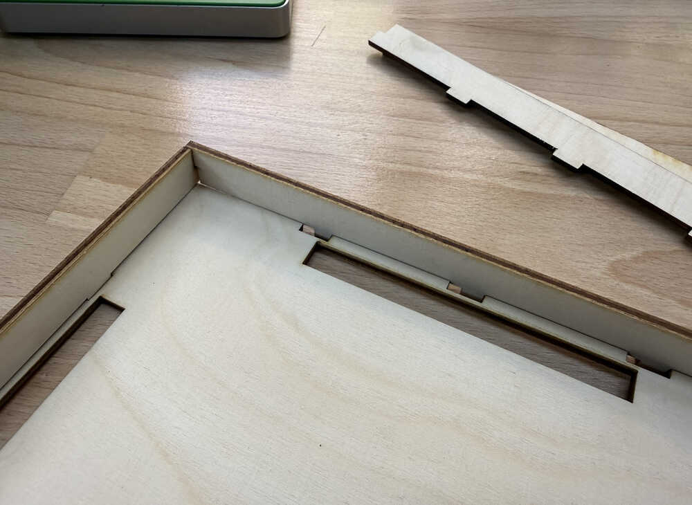
I changed the design and cut them again.
You can find the link to the new design below and in the .zip file.
The laser cutter didn't cut some of the parts properly, so they're stuck, so I'll have to cut them again.
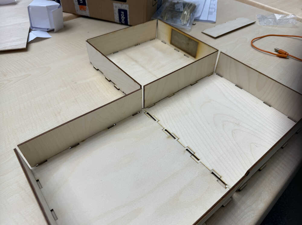
The top part is done!
They don't break off easily.
Files
Here are the files.
Here is my Cuttle design.
Carrier-Bot | Finishing | Update 6
Info About the Update
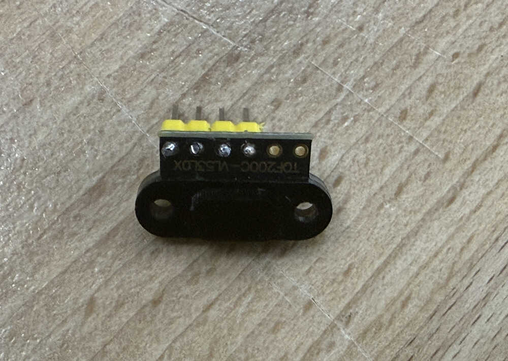
This update is basically me making a working robot. My conditions are that I can start it from my a website in computer, it doesn't break down mid-task, and that its program (that I'll write in this update) actually works. I'll later make another update named "improving", which will basically focus on making the robot more user-friendly and better in general (it'll have some more functions). Also, since there's no VL53L1X in stock, I'll be using a VL53L0X for my robot instead.
Table of Contents
- Connecting to PCB
- Website
- Casting Wheels
- Assembling
- Creating the Maze
- Coding
- Remaking the PCB
- Files
Connecting to PCB
You can find how I connected to my PCB in my week 11 documentation.
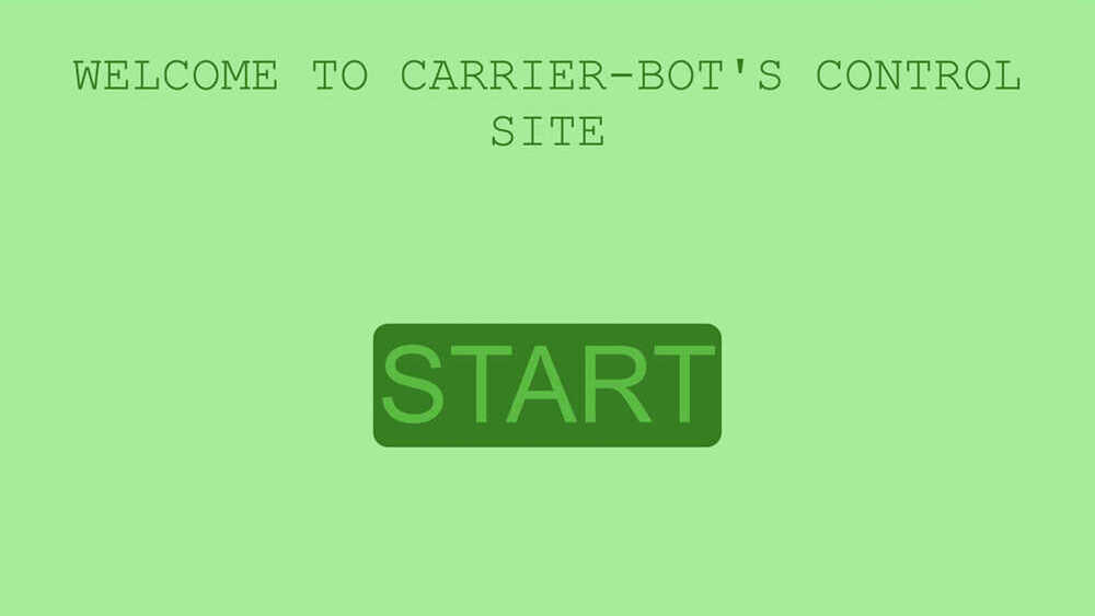
Website
This part is about me writing code to create a local site to control my robot. You can find the details in my week 14 documentation.
Photo of website:
Casting Wheels
I'll be creating the mould and will cast two wheels with 50mm diameter (25mm radius) and 5.5mm thickness. The full documentation can be found in my week 13 documentation.
Milled wax:
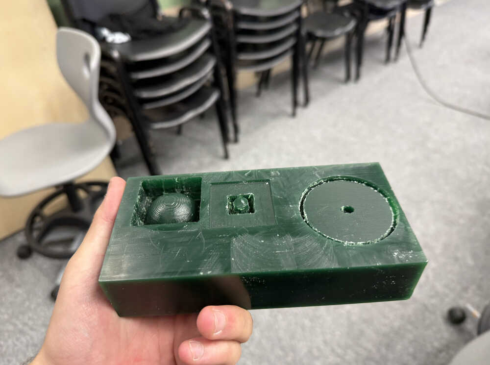
The mould:
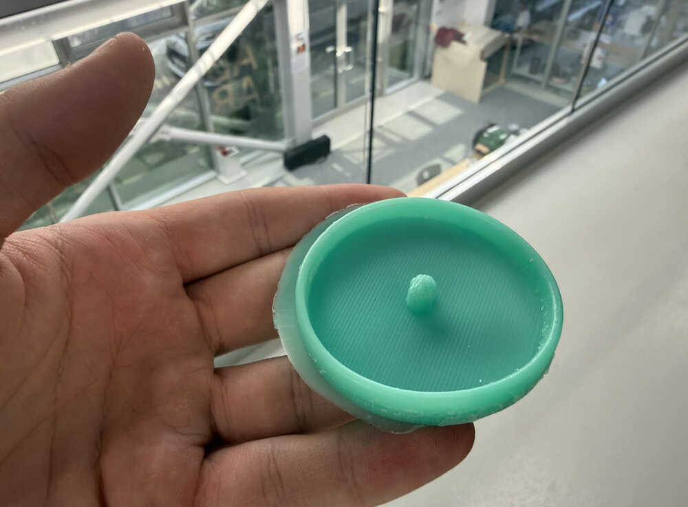
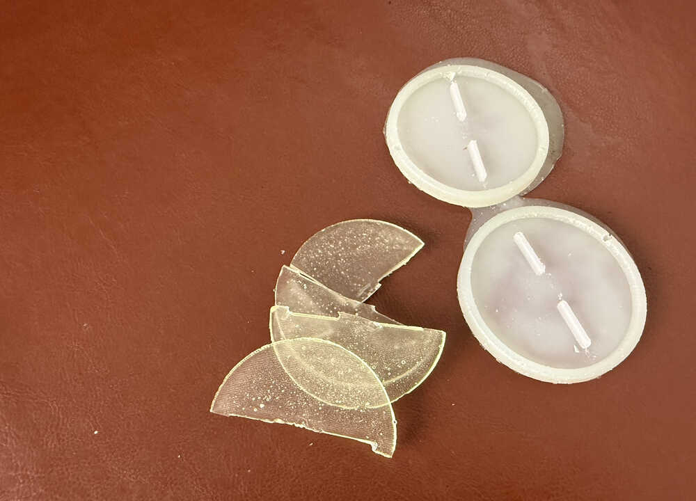
After casting:
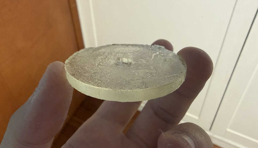
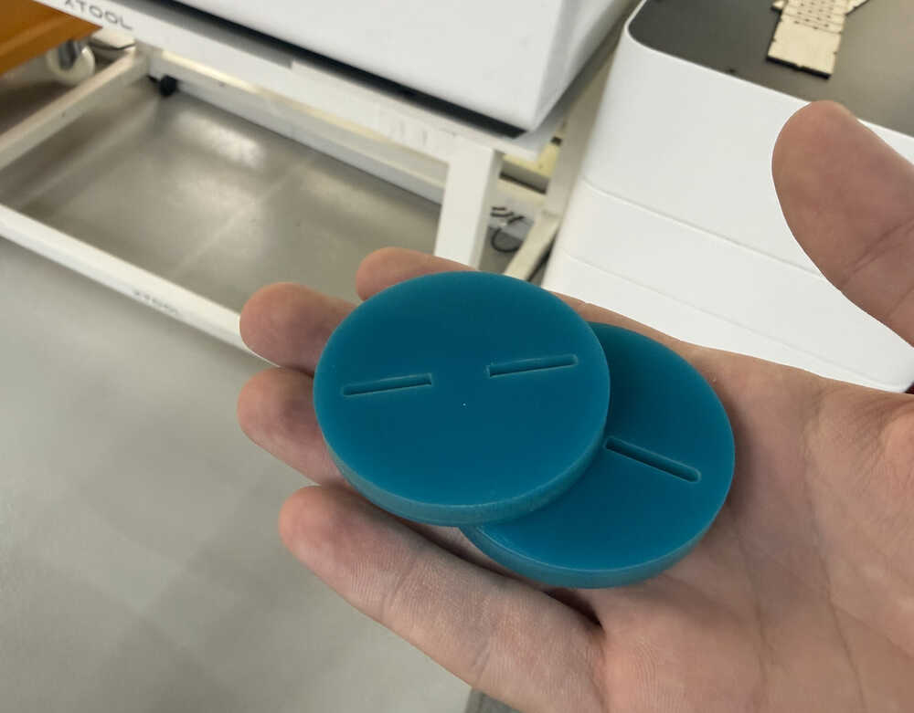
Because the wheel broke down, I decided on using rigid cast for my wheels, so here's a photo of the rigid wheel I made.
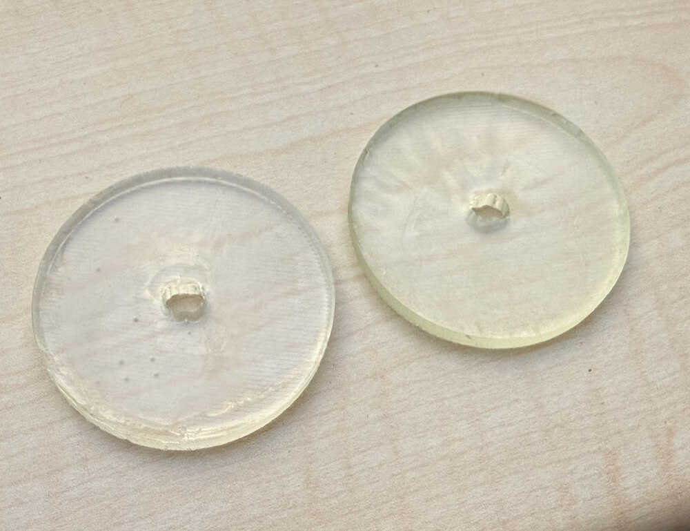
These ones also aren't that good. After testing, I learned that they can't stand higher weight; as in, they stop turning. I decided on making one that I can screw to a servo horn. The servo horn is about 2.3mm thick, so I'll make the new wheels 3mm thick.
As it can be seen, the thickness is now 3mm.
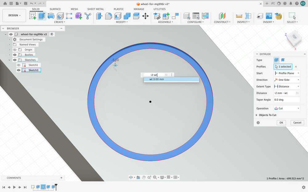
The servo horn is 37mm, so I'll make a hole that is 40mm with 2.2mm width.
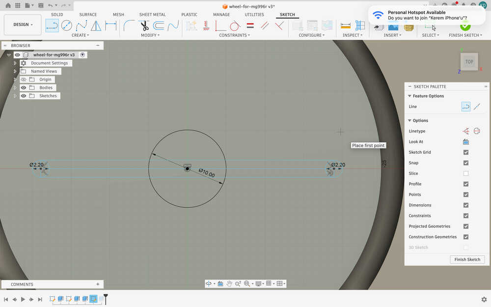
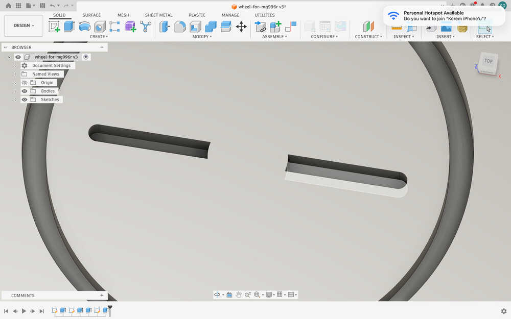
After extruding:
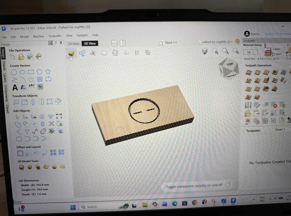
I sent the stl file to the milling computer.
I opened my design in VCarve.
I made a roughing toolpath.
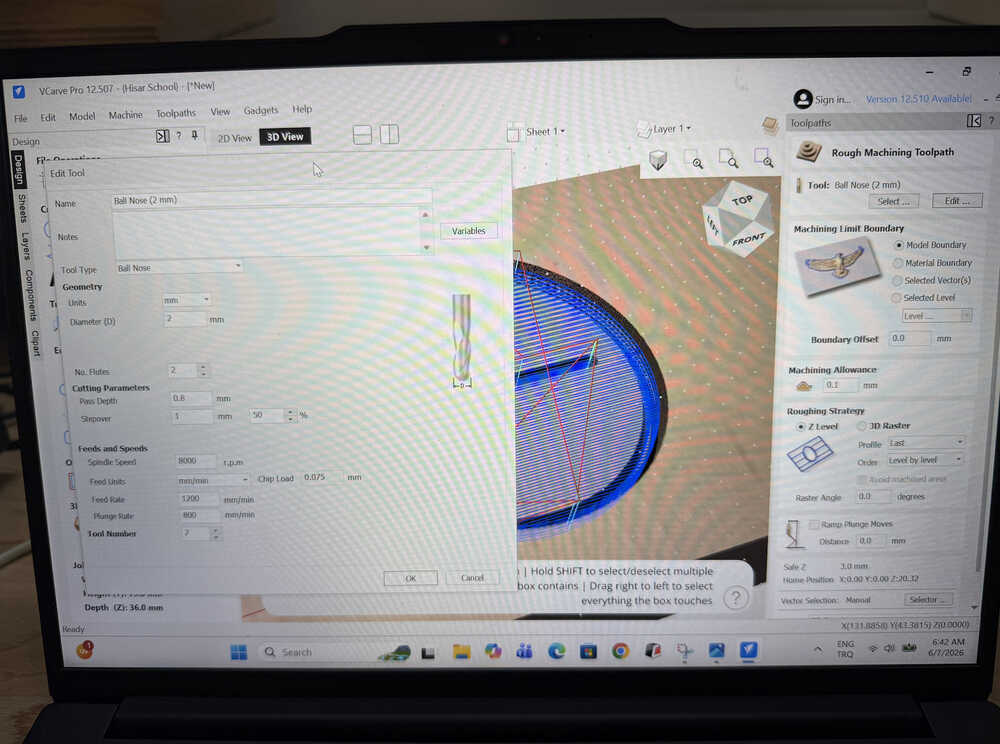
I made a finishing toolpath.
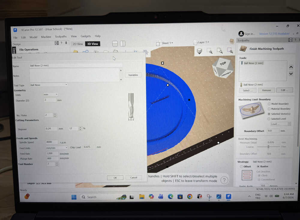
The program shows that it'd take about 23 minutes in total.
The milled wax:
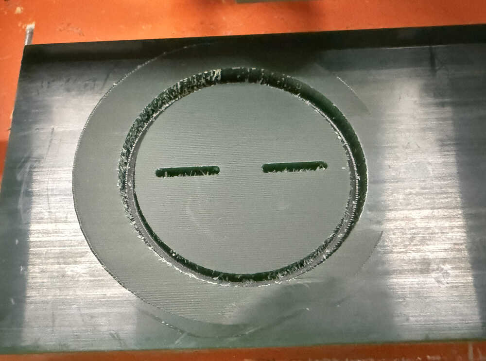
I'm now much better at making toolpaths than before.
Unfortunately, I will not be able to show the cast nor the mould in update 6. Even though this is under "Casting Wheels", I'm actually doing this last mould after finishing my code etc., so I won't be able to wait until the cast is finished before posting this update (basically, I'm out of time). Though, I'll follow the same procedure as the moulds before and I will be using rigid resin to cast this wheel. Also, you'll be able to see the wheels in the next update (probably). If not, in update 8.
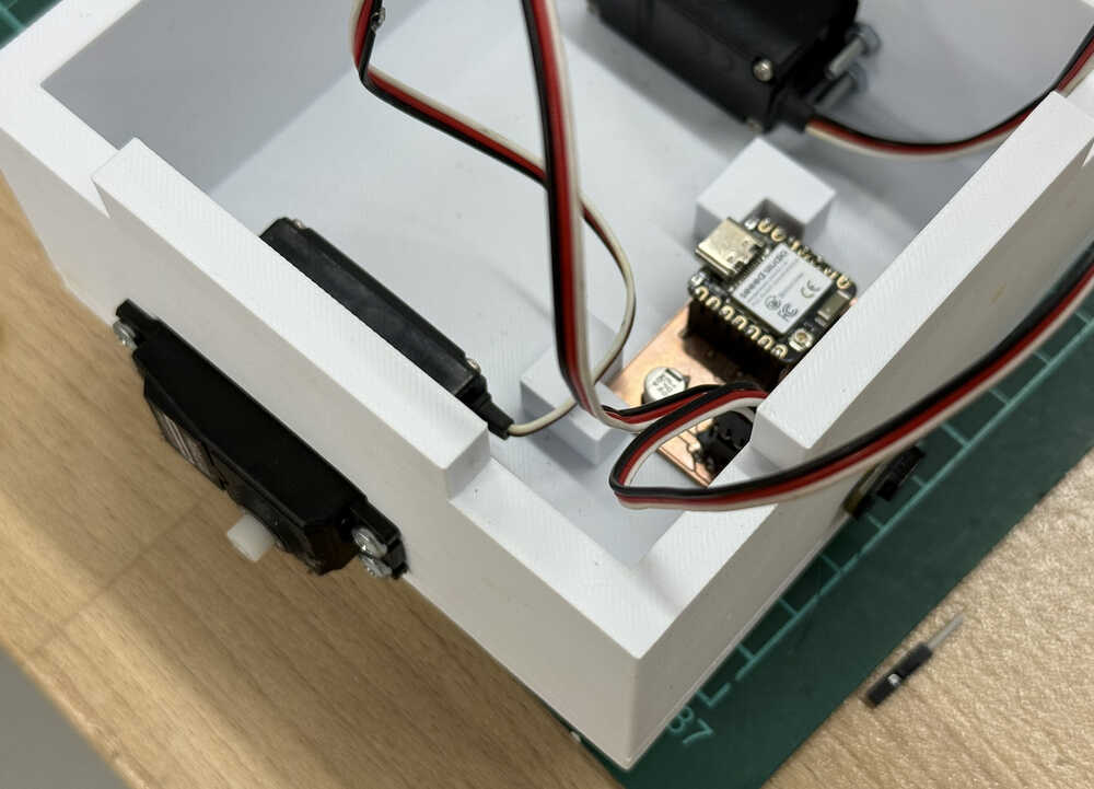
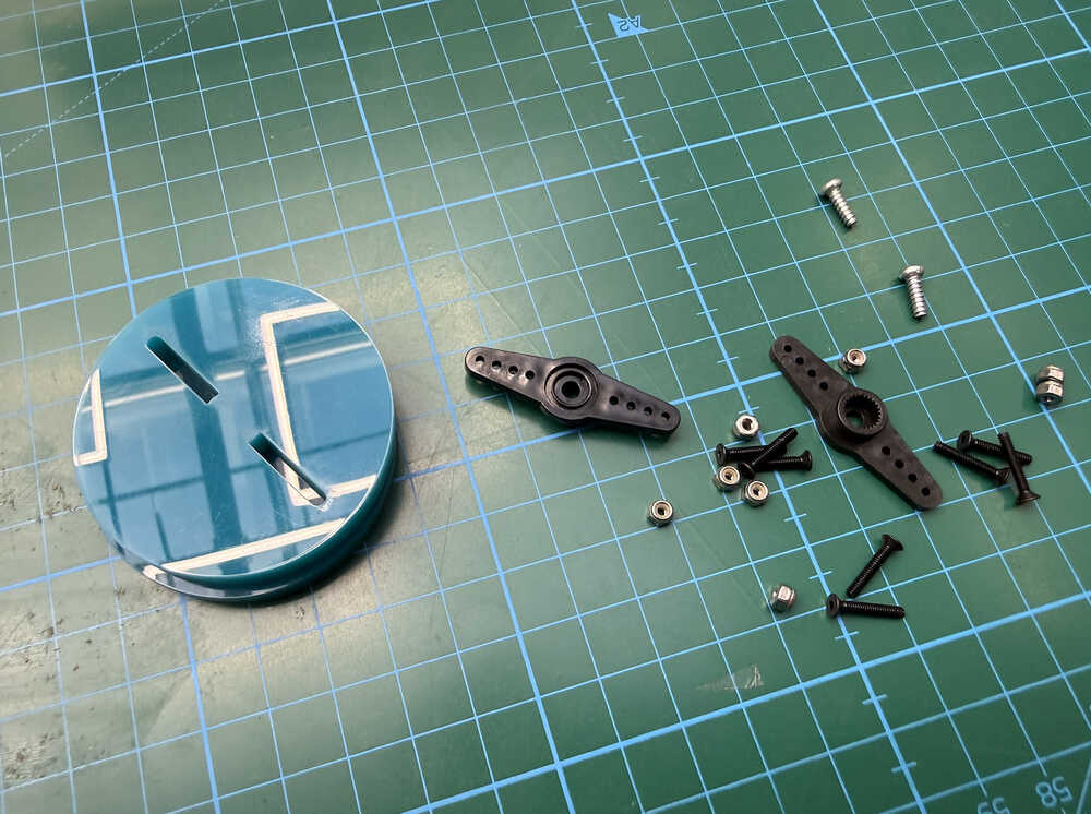
Assembling
I want to mention that, between update 5 and this update, the 3D design of my final project changed. You can, however, still find the new design in my week 15 documentation. Also, I changed the size of the top part, too. You can find it in the files section.
Assembled robot:
Creating the Maze
First, I need to find a suitable size for each tile in the maze. For this, I found the length of the line below.
The line is as long as √(2 * tpd^2), which is equal to 185.401mm. I decided to make the tiles 200mm by 200mm. Also, I decided to make the height of the walls 50mm.
I'm planning on designing a "platform" component, a "wall" component, and a "goal" component.
Here are the guides I made.
Basically, walls with 4 slots will be able to connect to this platform, and this platform will be able to connect to another one of it.
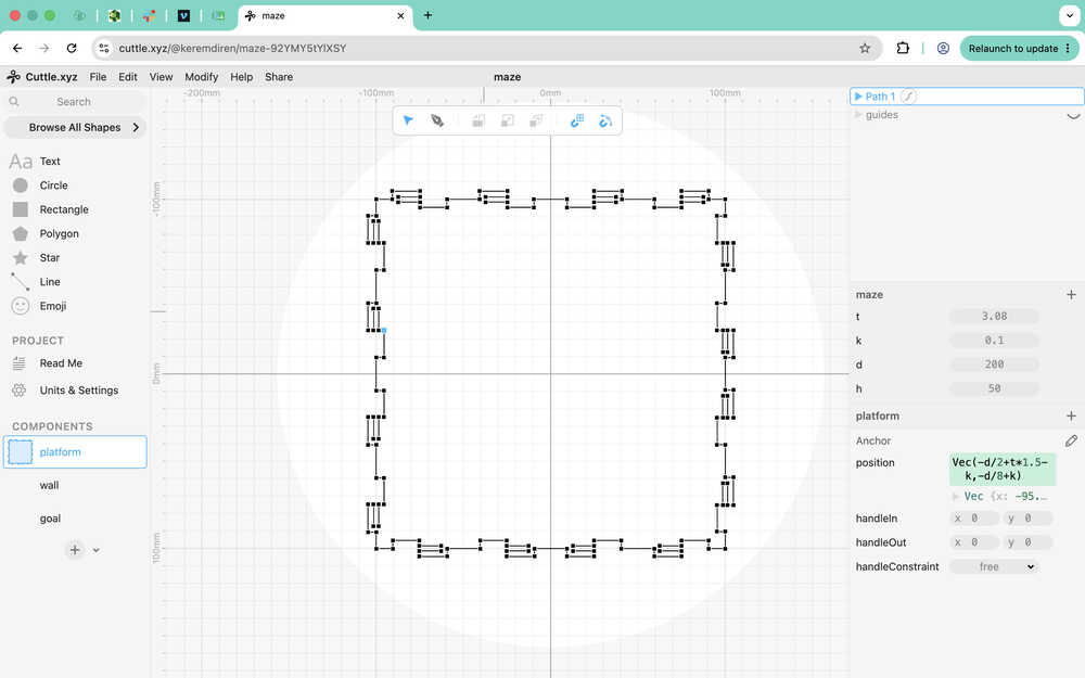
Here is the platform after using pen.
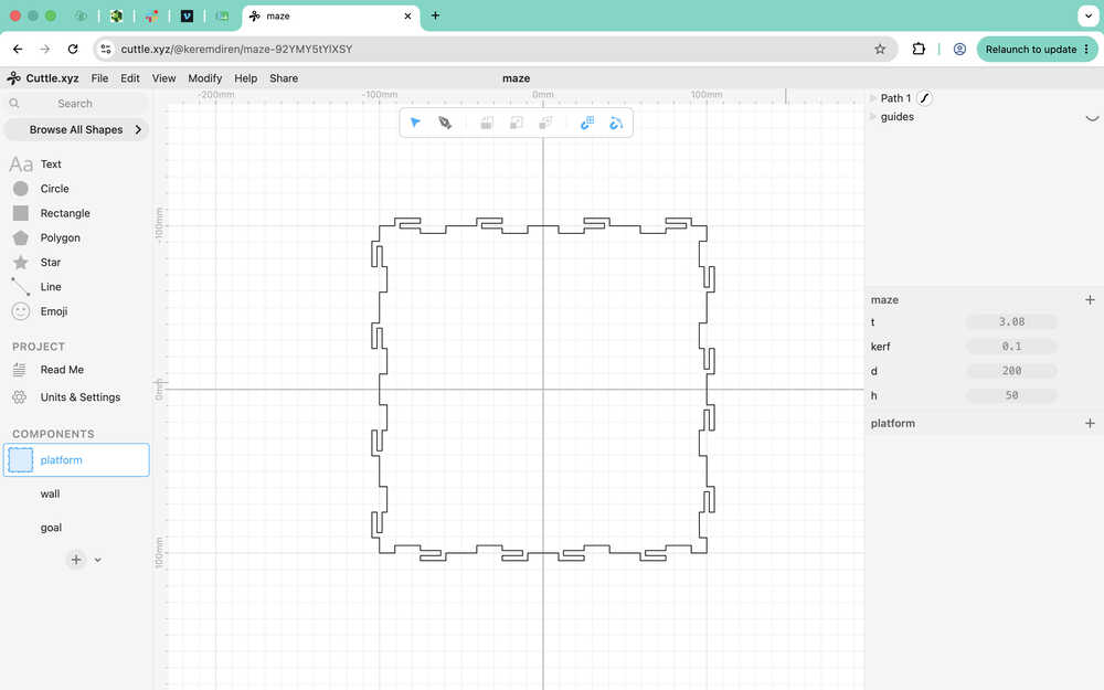
I made it parametric.
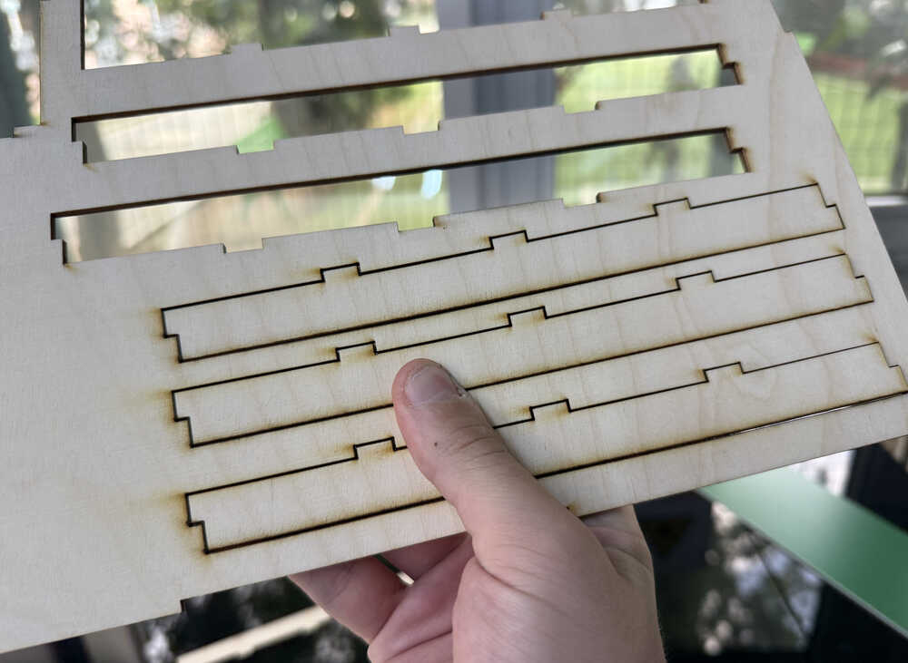
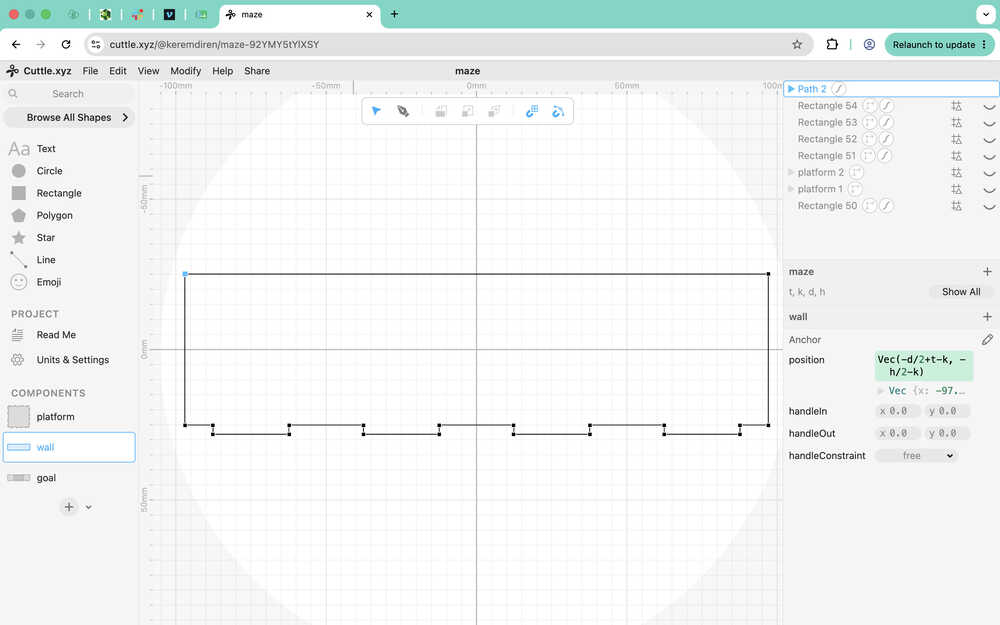
This is the guide I'll use for the wall.
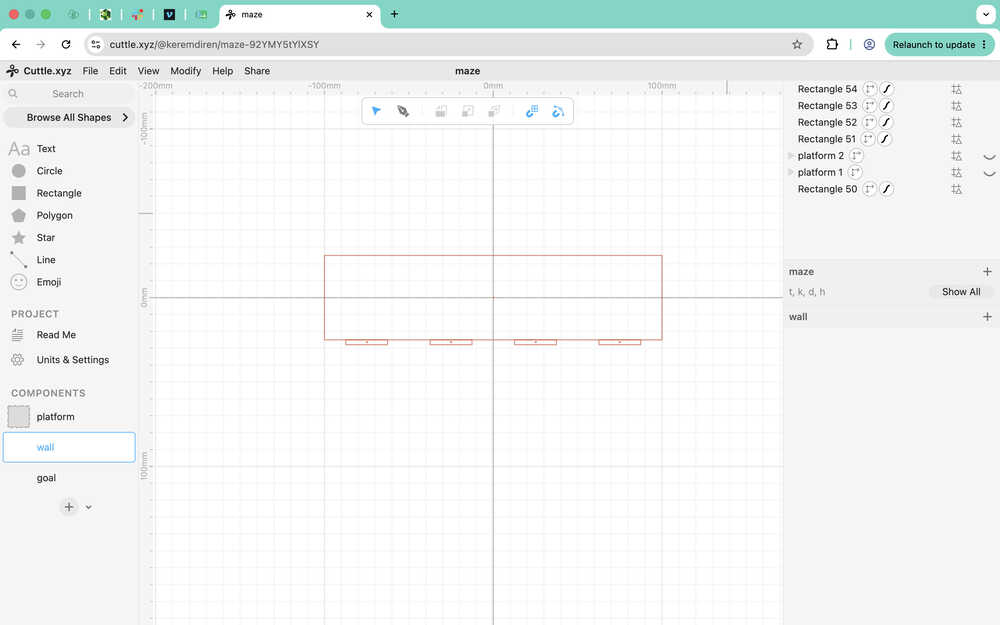
I used the pen to go over the guides.
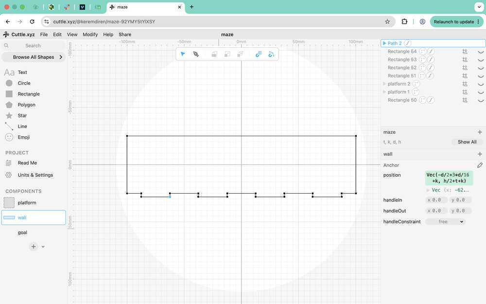
I made the design parametric.
This is the goal wall.
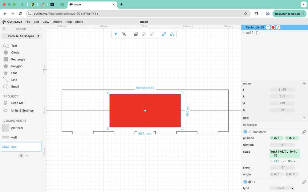
The middle red rectangle will be engraved.
I decreased the length of the wall by t since the walls would've overlapped otherwise.
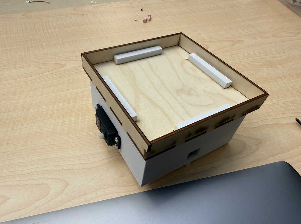
I cut the parts with 70% power and 30mm/s speed, and engraved the goal with 34% power and 200mm/s speed; although, I engraved the goal two times over.
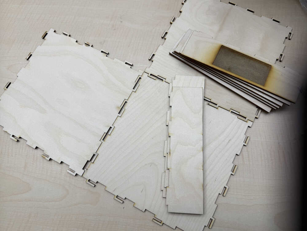
After assembling.
Remaking the PCB
I'm not content with the current PCB. I want it to have an external power input so that the servos don't start causing problems because of current problems etc. Also, I want to turn the pin headers that go to the servos into vertical ones. I'll be using batteries to power the PCBs while I'll be using a small powerbank to power the XIAO ESP32C6. I'll also change the pin headers for the ToF to pin sockets.
This is the new design of the PCB:
This is the new layout of the PCB:
I milled it:
I soldered it:
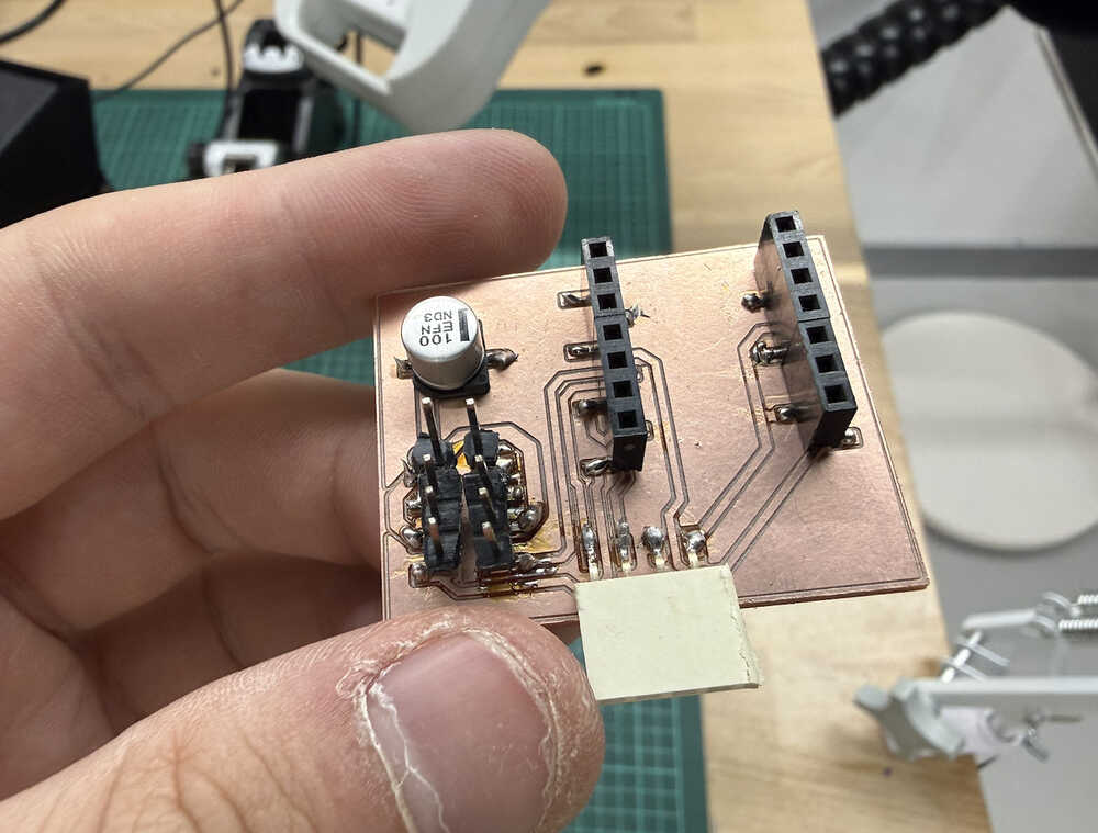
I soldered the ToF and cut the sharp solder parts:
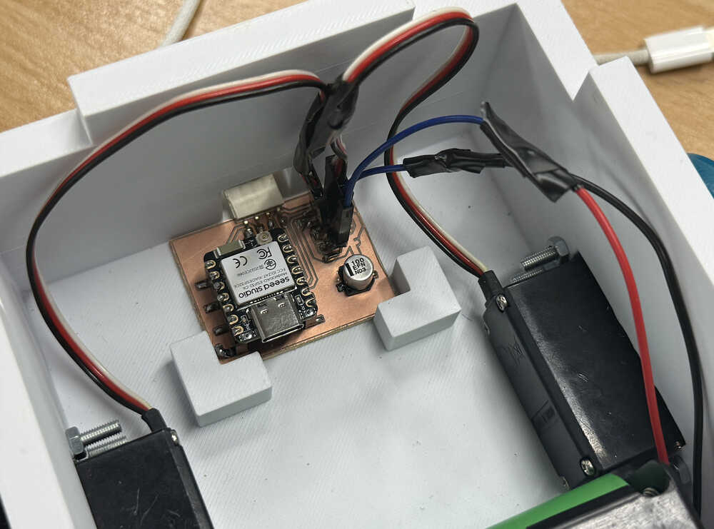
The robot with the new PCB and the ToF:
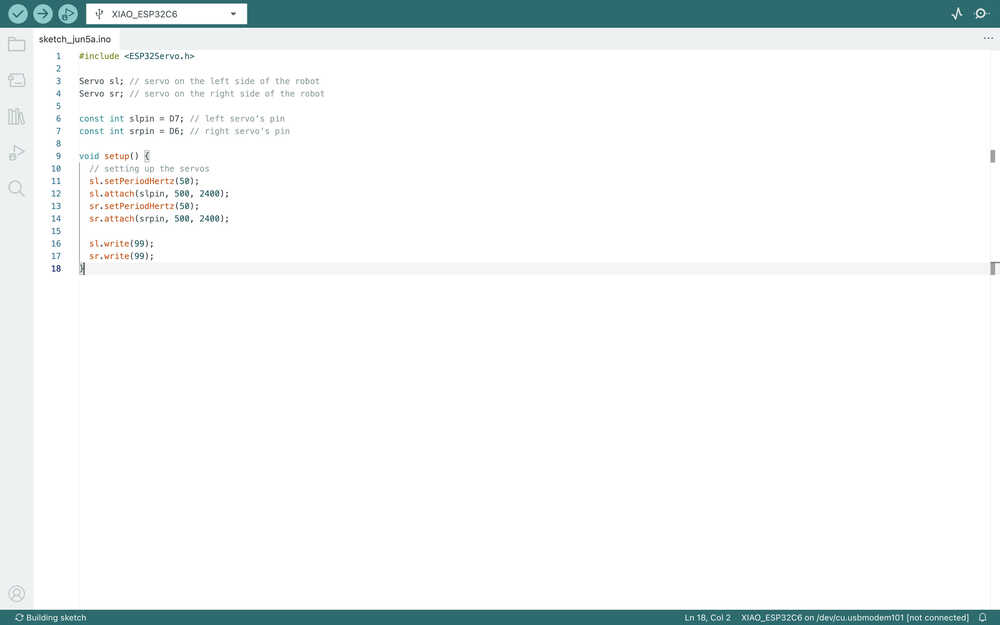
Coding
My code in week four won't work by itself since, firstly, it isn't made to control servos; secondly, it does not fit the current maze. The code was so that every position was either filled or empty, so it didn't account for the fact that I'm now using thin walls that stand between positions. Although, I can still alter the main algorithm to create something usable, so I'll do just that. Also, I'll add a button to the site so that the start and goal locations can be made known to the robot, since the program I'll be writing works best with those two known.
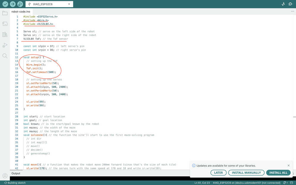
I started by setting up the servos.
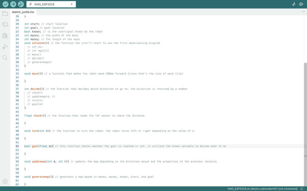
I defined some variables, functions etc. and showed which function will be used in which function by writing them next to //. These may change as I'm writing the code.
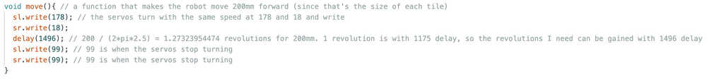
The move function.
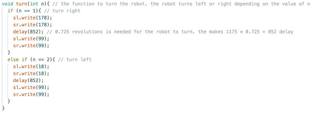
The turn function.
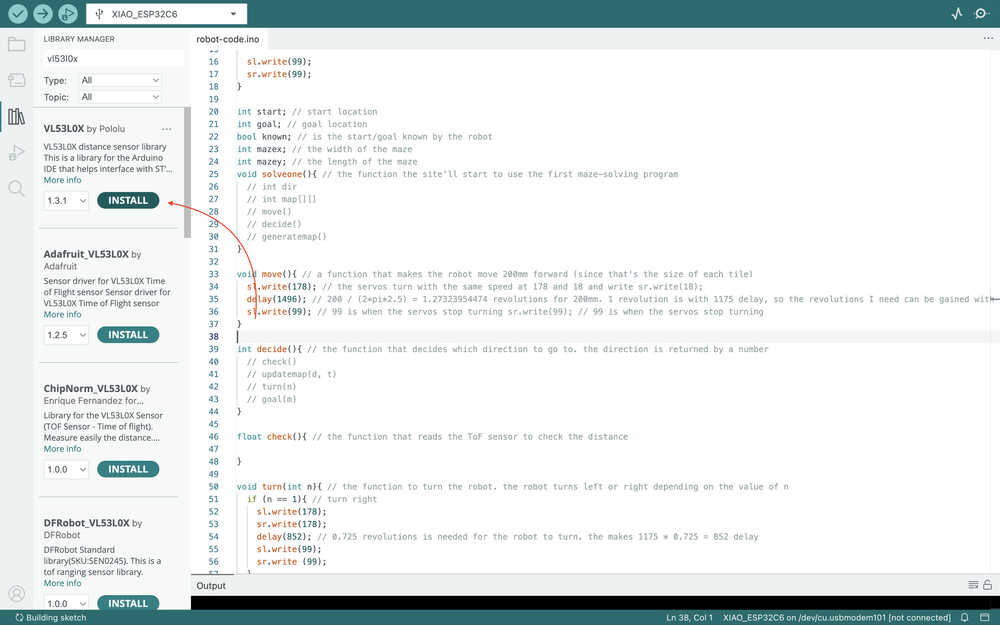
I asked ChatGPT I have a VL53L0X. How can I measure distance with it using Arduino IDE?. I also sent the link of the ToF I'm using.
I downloaded the required library.
I tested the code given by ChatGPT.
I added this part to my code:
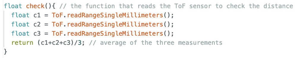
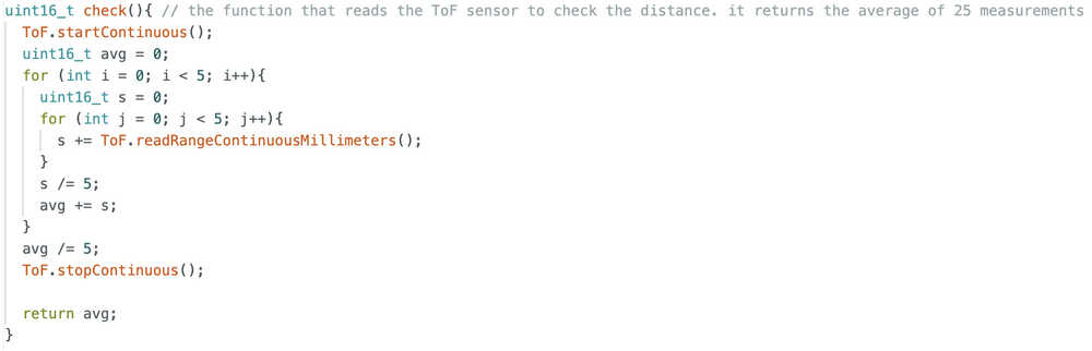
This is the check function now.
I realized that, unlike my week four code, I didn't need a "generatemap" function, so I erased it. This is the part I added to solveone instead of that.
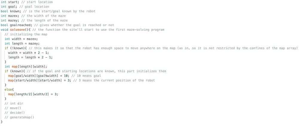
I added this part to the solveone:
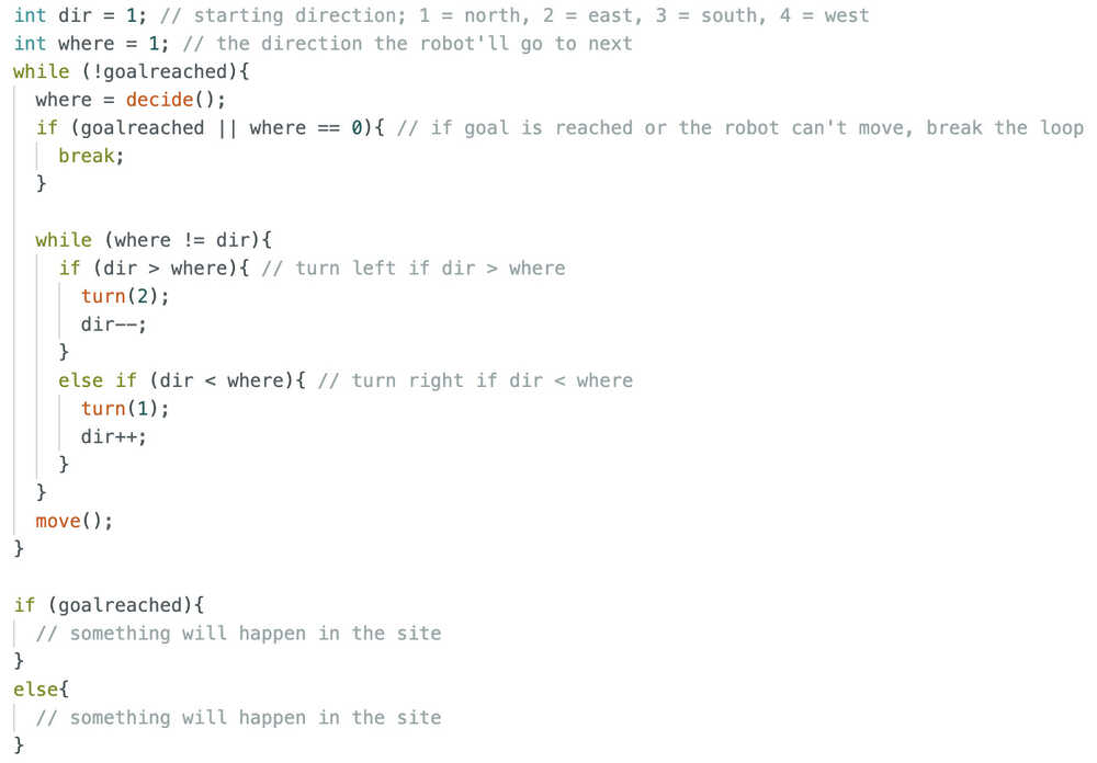
Basically, after deciding where to go, the robot turns until it looks at that direction; then, it moves there. If the robot reached the goal or can't move, the program stops. The user should position the robot such that it looks the the upper part of the maze.
I want to mention that I have decided to put a material hard to detect at the goal wall so that I can detect it is the goal when the value becomes huge. That's why I updated the check function. I got help from ChatGPT; as in, I learned what uint16_t is (basically an int type that is better for measurements since it doesn't have negative values and thus has a bigger max value) and what continuous measurement is.
I added a variable named "current" that signifies the current location of the robot in the map. It is initialized to be "start" if start is known; if not, it is the middle of the map.
This is the goal function.
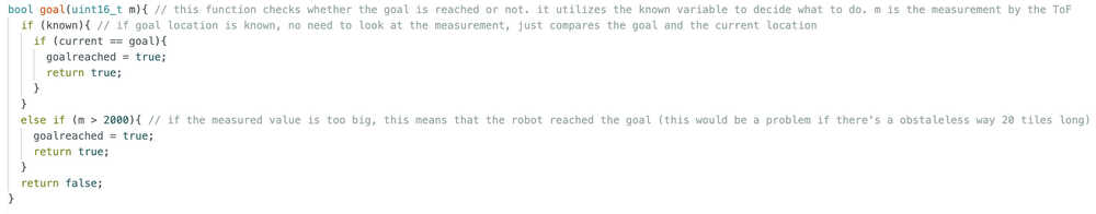
As I said above, if the hard-to-detect material is in front, the measurement will be very high, so the robot will have reached the goal.
The updatemap function:
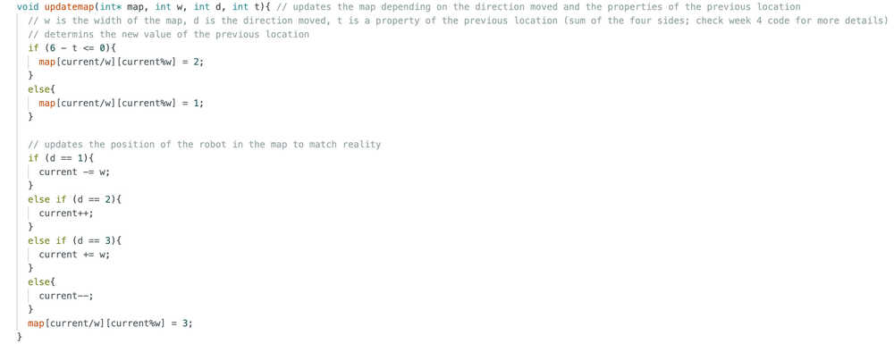
Updates the map and the "current" variable.
I added this part to the decide function.
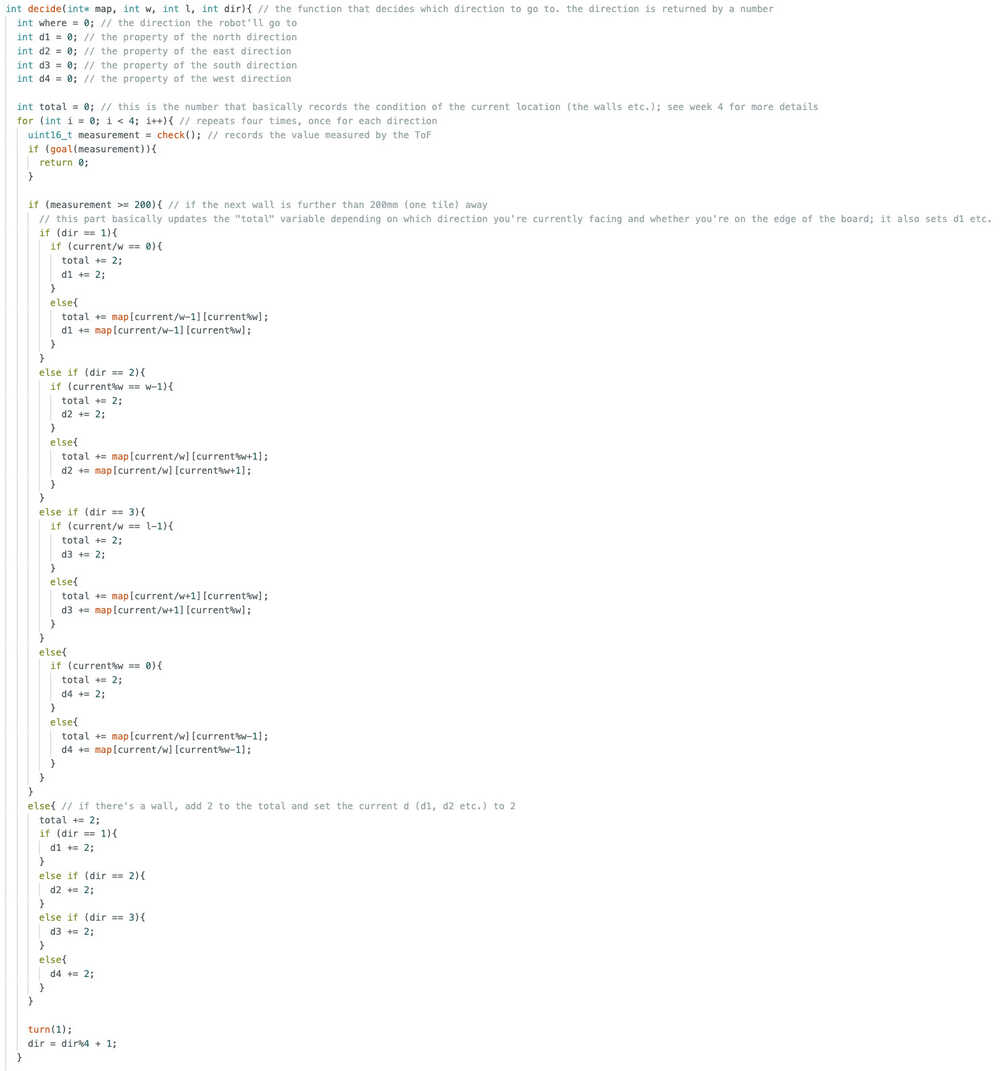
This part basically measures values, stores values, checks whether the gole is reached, and initializes some variables.
This is the second part of the decide function.
This part basically decides where to go depending on the previously measured values. It also calls the updatemap function.
With this, the main algorithm is done. Now, I only need to implement this code to the side code.
I copied and pasted the code to the site code. I also replaced the start button with solveone, so, now, the solveone function is called when the "START PROGRAM" button is clicked. Also, I added this part to solveone so that something happens when the program ends, although I have not decided what yet.
        String finish;
        if (goalreached){
	        finish = R"rawliteral(
          <!DOCTYPE html>
	        <html>

	        </html>
	        )rawliteral";
        }
        else{
	        finish = R"rawliteral(
          <!DOCTYPE html>
          <html>

	        </html>
	        )rawliteral";
        }
        server.send(200, "text/html", finish);
I added the <button onclick="window.location.href='/goalstart'" style="background-color: green; color: rgb(37, 188, 37); cursor: pointer; border: none; align-content: center; font-size: 60px; text-align: center; border-radius: 20px;">MAKE GOAL/START KNOWN</button> button to the control page.
I added server.on("/goalstart", goalstart); to the setup. Now, when the button is clicked, this page will open.
I asked ChatGPT How can I get text input in HTML?. I got <input type="text" id="name" name="name" placeholder="Enter your name">. I also learned how to save the variable.
This is the goalstart function.
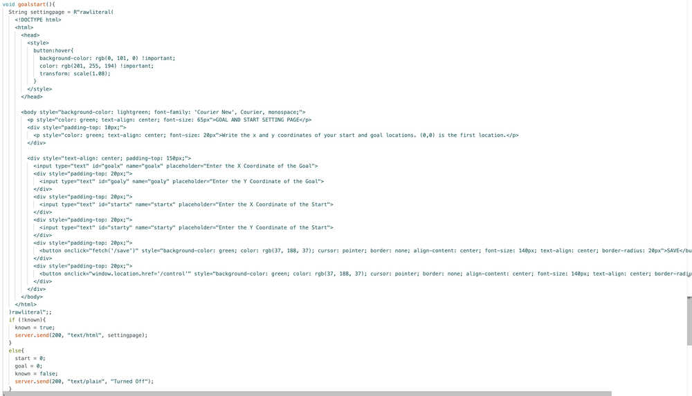
It basically gets four inputs to set the start and goal variables.
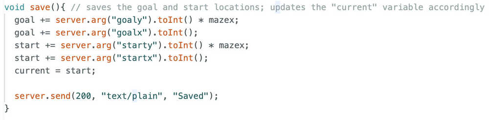
This is the function that saves the inputted values.
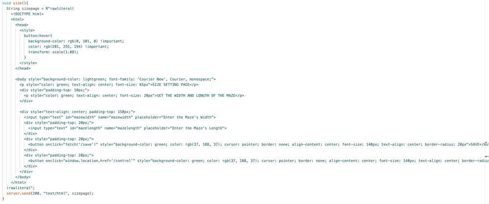
I added <button onclick="window.location.href='/size'" style="background-color: green; color: rgb(37, 188, 37); cursor: pointer; border: none; align-content: center; font-size: 60px; text-align: center; border-radius: 20px;">SET MAZE SIZE (MANDATORY)</button> to the control page.
This is the size function.
This is the new save function.
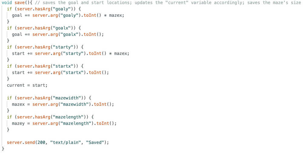
Since both size and goalstart functions use this function, I had to separately check which variables were being saved.
Debugging
After trying the code, there were some problems with compiling. I fixed them. Basically, except some typos and name conflicts, there weren't any problems. The code is mainly the same and you can find it in the files section below. Although, when I clicked the called the goalstart function a second time, instead of just setting the "known" variable to false, the site turned into a white page with "Turned Off" written at the top left. After I asked ChatGPT, I learned that this was because the site was expecting HTML (since that's what I assigned to the button), but I was sending plain text, so the server turned it into HTML. I solved this problem by erasing the server.send(200, "text/plain", "Turned Off"); text and writing control() instead (this opens the control page, the page the site was already on, once more, which is basically like refreshing the page).
I added this part to the beginning of solveone because I couldn't start the program multiple times.
        // initialize variables in case of starting once again
        bool goalreached = false;
        int current = start;
After testing a bunch of times, I learned the remaining problems with my code:
- I accidentally redeclared the goalreached and current variables locally in solveone
- The ToF reads a value larger than 2000 for some reason
- I forgot to finish the decide function (the ydif-xdif part) (it doesn't utilize d1, d2, d3, and d4)
- The start location, goal location, and maze size saving system doesn't work; as in, the function gets called, but doesn't save the enter values
I solved the first problem by just erasing the "bool" and "int" at the front of the goalreached and current variables inside solveone.
After testing with other code, I found out that the problem with the ToF is because the ToF connection part of the PCB wasn't properly soldered. I mean, with my old PCB, the sensor works fine, but with the new one, it keeps measuring 8191.
After adding more solder to some parts, the sensor started to work again. However, after some time, the problem returned. However, the testing code I was using to test the ToF started to work. This meant that soldering DID work, but the problem persisted because of something else. After looking at the differences between my main code and the testing code, I realized that I was using readRangeSingleMillimeters() in my test code while I was using readRangeContinuousMillimeters() in my main code. After changing the readRangeContinuousMillimeters() to readRangeSingleMillimeters(), the check function started to work again, so this problem is now fixed.
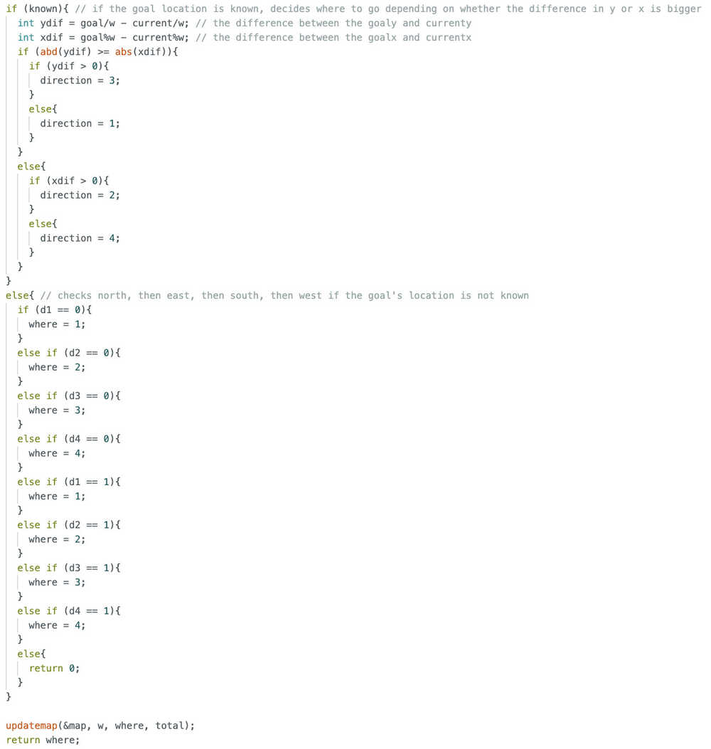
The ydif-xdif part now looks like this.
        if (known){ // if the goal location is known, decides where to go depending on whether the difference in y or x is bigger
          int ydif = goal/w - current/w; // the difference between the goaly and currenty
          int xdif = goal%w - current%w; // the difference between the goalx and currentx
          if (abs(ydif) >= abs(xdif)){
            if (ydif > 0 && d3 == 0){
              where = 3;
            }
            else if (ydif < 0 && d1 == 0){
              where = 1;
            }
            else if (xdif > 0 && d2 == 0){
              where = 2;
            }
            else if (d4 == 0){
              where = 4;
            }
            else if (d2 == 0){
              where = 2;
            }
            else if (d1 == 0){
              where = 1;
            }
            else if (d3 == 0){
              where = 3;
            }
            else if (ydif > 0 && d3 == 1){
              where = 3;
            }
            else if (ydif < 0 && d1 == 1){
              where = 1;
            }
            else if (xdif > 0 && d2 == 1){
              where = 2;
            }
            else if (d4 == 1){
              where = 4;
            }
            else if (d2 == 1){
              where = 2;
            }
            else if (d1 == 1){
              where = 1;
            }
            else if (d3 == 1){
              where = 3;
            }
            else{
              return 0;
            }
          }
          else{
            if (xdif > 0 && d2 == 0){
              where = 2;
            }
            else if (xdif < 0 && d4 == 0){
              where = 4;
            }
            else if (ydif > 0 && d3 == 0){
              where = 3;
            }
            else if (d1 == 0){
              where = 1;
            }
            else if (d3 == 0){
              where = 3;
            }
            else if (d4 == 0){
              where = 4;
            }
            else if (d2 == 0){
              where = 2;
            }
            else if (xdif > 0 && d2 == 1){
              where = 2;
            }
            else if (xdif < 0 && d4 == 1){
              where = 4;
            }
            else if (ydif > 0 && d3 == 1){
              where = 3;
            }
            else if (d1 == 1){
              where = 1;
            }
            else if (d3 == 1){
              where = 3;
            }
            else if (d4 == 1){
              where = 4;
            }
            else if (d2 == 1){
              where = 2;
            }
            else{
              return 0;
            }
          }
        }
Basically, it now accounts for d1, d2, d3, and d4, which means it now thinks of whether there's a wall, whether there direction is somewhere the robot has been at before etc.
For the saving problem, I asked ChatGPT. Apparently, right now, the things I enter into the input text box don't stay when I click save.
This is what ChatGPT wrote:
        <button onclick="saveMaze()">SAVE</button>

        <script>
          function saveMaze() {
            let width = document.getElementById("mazewidth").value;
            let length = document.getElementById("mazelength").value;

            fetch(`/save?mazewidth=${width}&mazelength=${length}`);
          }
        </script>
Apparently, this makes it so that the program calls the save function while sending the given values to the XIAO ESP32C6, which is what we want, so I implemented these changes to both the size function and the goalstart function.
While I kept testing, for some reazon, the d1 variable etc. kept getting -1515870811 as its value. After thinking and testing a bit, I realized that it might be caused because of the map array. After asking ChatGPT what a new array is initialized to, I learned that they were initialized to weird numbers if they were created local to a function. That's why I added a nested for loop to initialized every value of the map function to 0 before the start and goal locations were initialized.
I also realized that I made some mistakes while turning things such as map[current/w][current%w] to map[current]. As in, I made mistakes while turning 2D array locations to 1D array locations. What I did was basically deleting the ][ in the middle and adding + there without thinking much. After looking at the results all confused, I realized that this was the problem, so I fixed it.
I also deleted the 3 and 10 setting code in the map since they don't really affect the robot. They were in my week 4 code so I added them here but now realized that they were only useful in my week 4 code.
I gave half of my life to writing this code, but, with this, my code is now finally finished (at least for this update)! You'll be able to see the robot working in the next update or the one after that (update 8 will be about me working on my video and poster, so the robot will be working there 100%).
Files
Here are the files.
You can find the new top part design here.
You can find my maze design here.
Carrier-Bot | Improving | Update 7
Info About the Update
This update is about improving the project so that it does its job in a better way, and so that it has more functions.
Table of Contents
- Wheels
- Goal Reached / Couldn't Be Reached
- Random Maze Generator
- Control it Yourself
- Other Maze Solve Programs
- Files
Wheels
My wheels didn't make it.
Because I don't have any time remaining, I'll be making the wheels from the laser cutter. I'll cast the wheels once more, just in case they work this time. If they do work, they'll be ready by wednesday, which is one day before my presentation. I'll try to create the video and the new wheels today just in case the cast still doesn't work, but I'll change the video to the new version if the wheels do work.
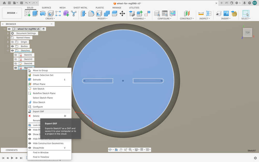
I used outline to sketch.
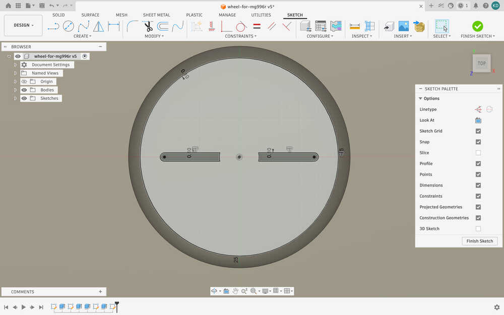
I exported the sketch as DXF.
Here are the wheels I cut from acrylic.
I used 100% power and 12mm/s speed. The wheels have a thickness of 6mm.
I've got everything ready. I just need to make the holes of the servo horn larger so that I can M2 screws with them.
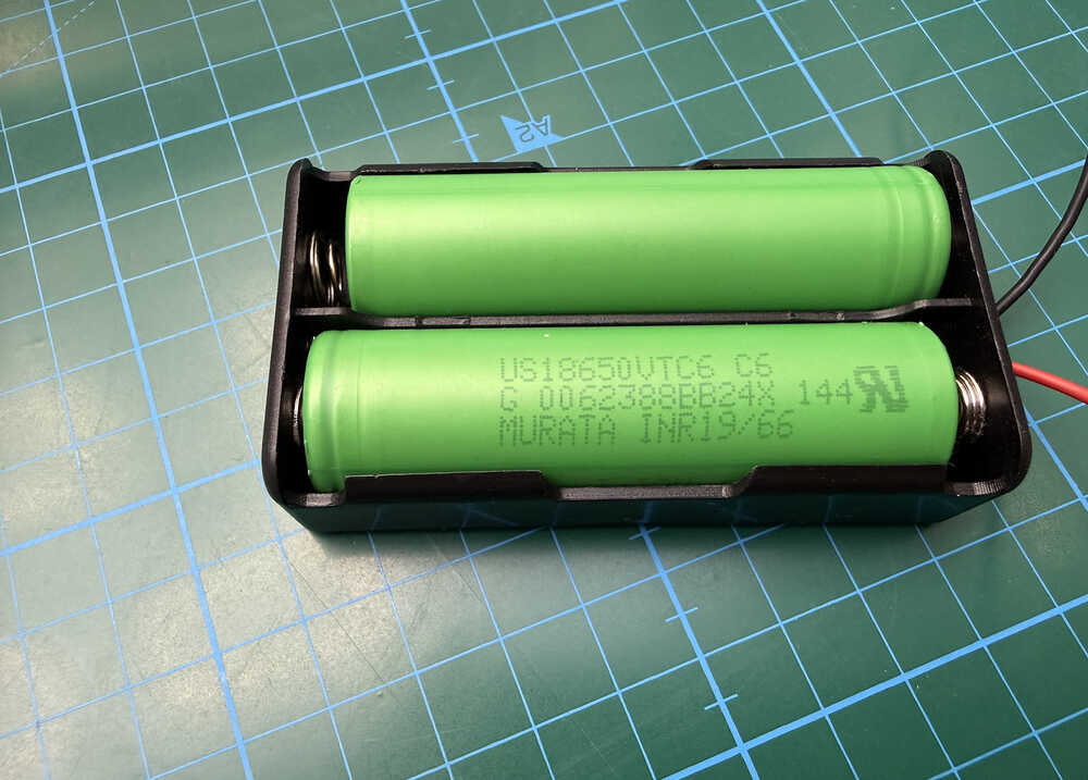
Also, I'll be using these to power my servos.
Thanks to Mr. Ömer Çavdar, I learned how to use a drill, and widened the holes of the servo horns.
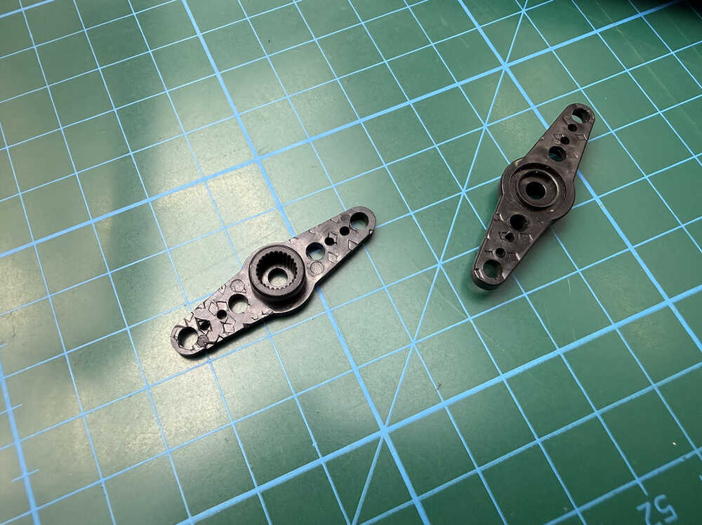
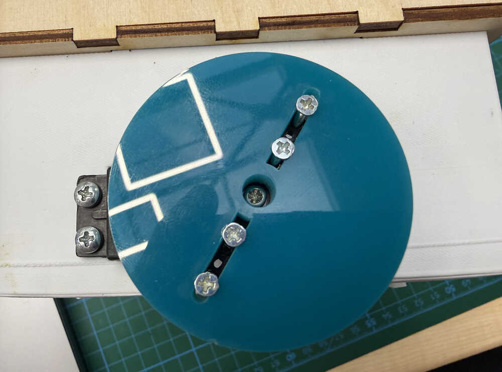
Also, I opened holes in the middle of the wheels to make it easier to screw to the servo.
I screwed the wheels and the servo horns together.
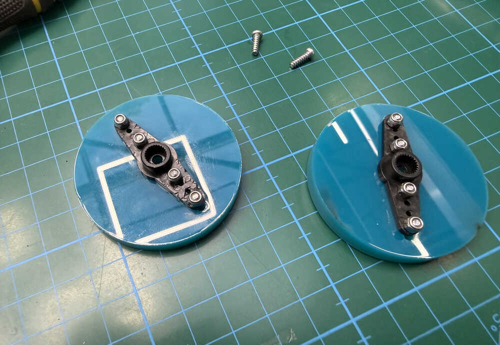
I screwed the wheels to the servos.
I used two crocodile cables for the servos' power.
I'll work on the cables before making the video.
Goal Reached / Couldn't Be Reached
I started by changing fetch('/start') at the start button to window.location.href='/start' so that I can change the page according to whether the robot found the exit or not.
I also deleted the end of solveone and changed it so that it calls a new function I'll be creating right now named "finish". This is so that when I add other maze-solving programs, I don't have to keep adding new finish page HTMLs.
I pasted the part I deleted from the end of solveone to the finish function; although, I changed the variables name to finishpage.
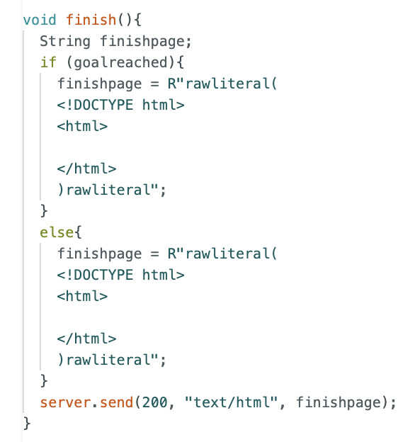
With the help of ChatGPT, I wrote this code, which is for when the robot solves the maze.
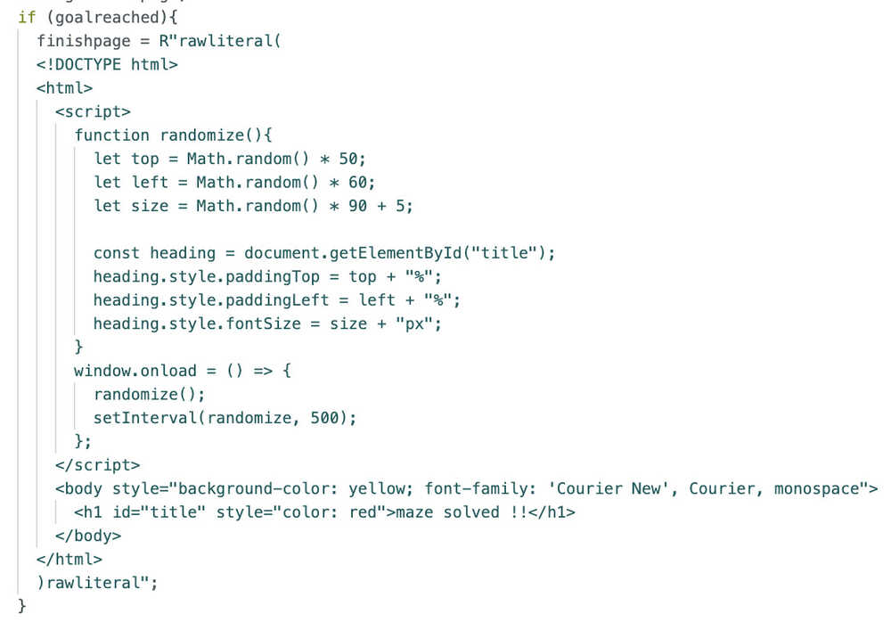
This is how it looks in practice.
I'm planning on making the screen change 3 times, then I'll go back to the control page.
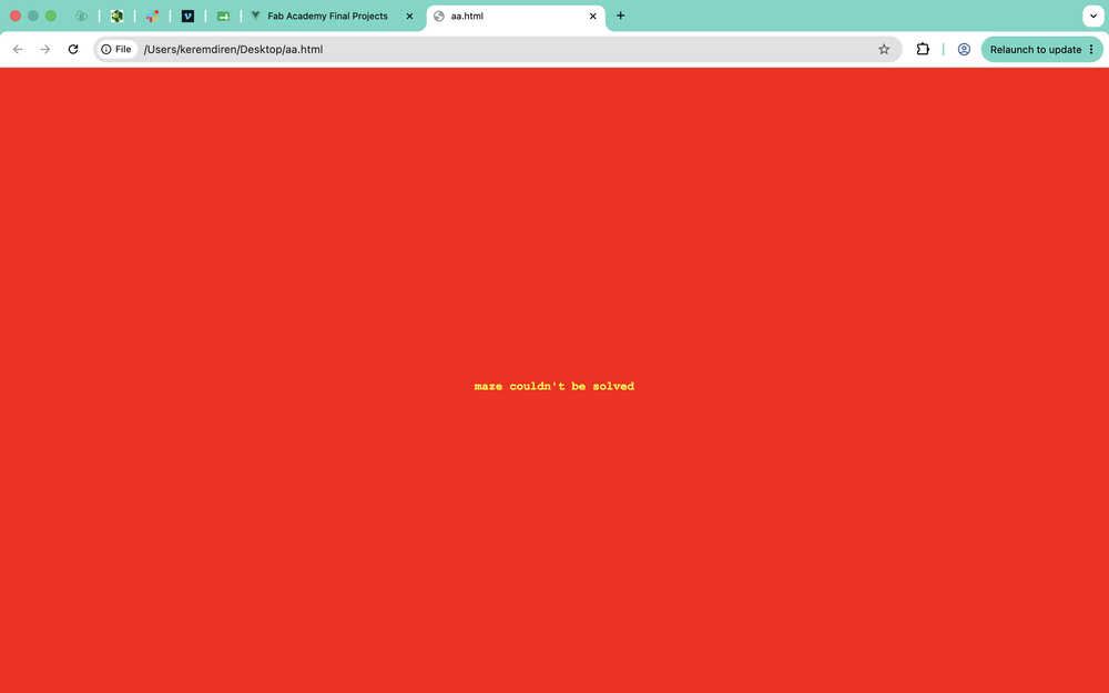
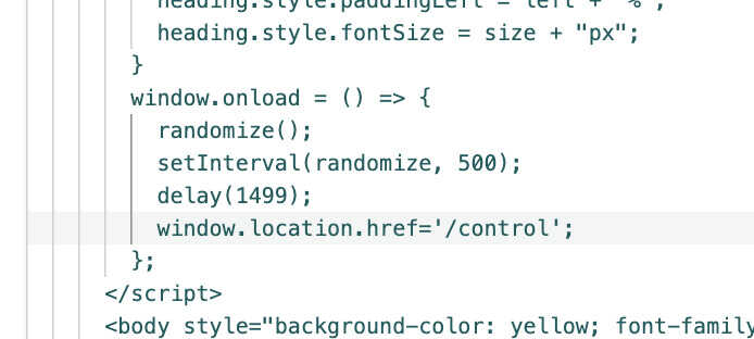
This is the code for when the maze couldn't be solved.
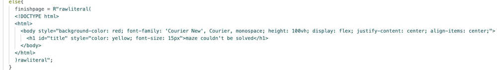
In practice:
I added this part so that the page goes back to the control page after 1.5 seconds.
After testing, it didn't even compile.
I thought of doing something like this.
It didn't work.
So, I changed it to this.
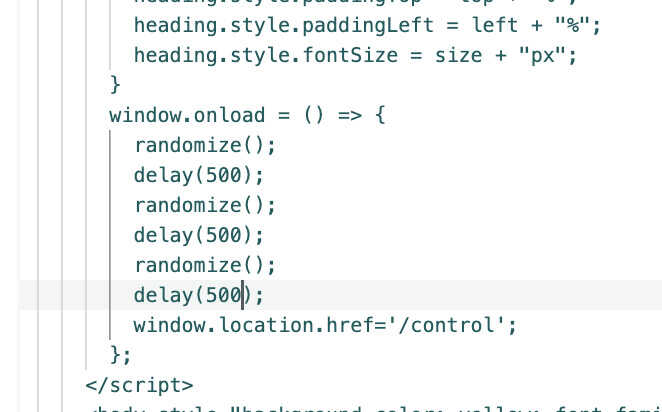
It didn't work.
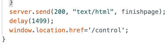
After asking ChatGPT, I added the thing it asked me. The part makes it so that, 1.5 seconds after the page opens, the control page is called again.
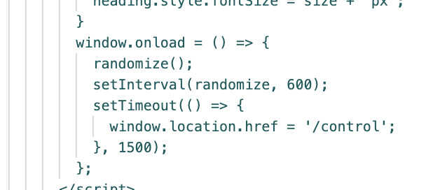
And the program now works; as in, it goes back to the control page 1.5 seconds later.
I added the same part to the not-finding part, too; although, I made its time 3 seconds instead of 1.5.
With this, this part is now finished.
Random Maze Generator
First, I added this button to the control page <button onclick="window.location.href='/generatemaze'" style="background-color: green; color: rgb(37, 188, 37); cursor: pointer; border: none; align-content: center; font-size: 60px; text-align: center; border-radius: 20px;">GENERATE RANDOM MAZE</button>. This basically opens a new page with the generatemaze URL.
I added server.on("/generatemaze", generate); to the setup. Now, the generate function (the function I'll write now) will be called upon this page opening.
I wrote this code:
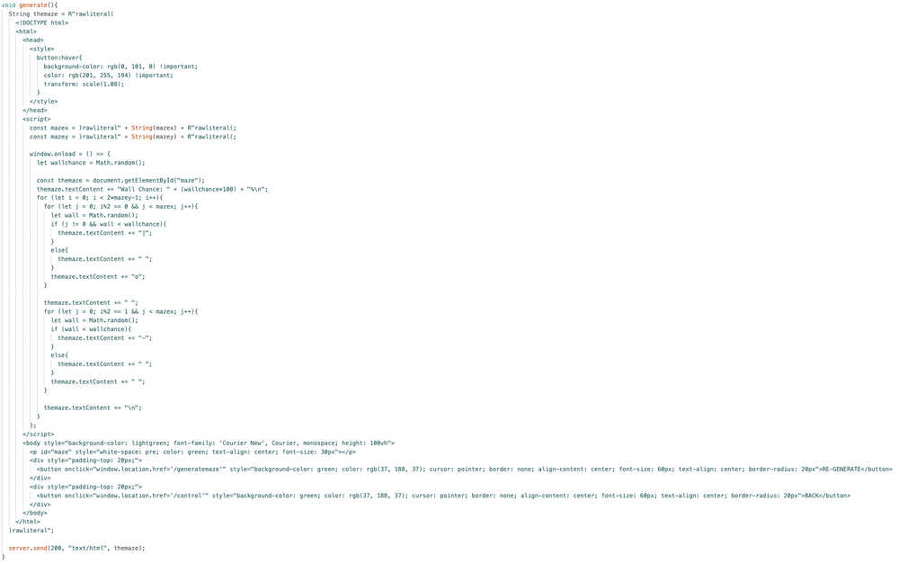
I did get from ChatGPT. I had problems with creating spaces, I didn't know how to use mazex and mazey inside of this HTML part, and I didn't know text-content existed.
In action:
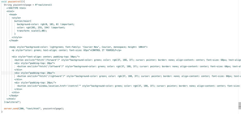
Control it Yourself
I started by adding a button for this page, which is <button onclick="window.location.href='/youcontrol'" style="background-color: green; color: rgb(37, 188, 37); cursor: pointer; border: none; align-content: center; font-size: 60px; text-align: center; border-radius: 20px;">CONTROL IT YOURSELF</button>.
This is the code I wrote:
While compiling, I got an error. It was because server.on("/leftward", turn(2)) was giving an error. Apparently, I can't enter parameters when calling functions from server.on. I mean, I kind of expected it since, even with functions that had no parameters, I only wrote the name and not the (). After Asking ChatGPT, I got the following code:
        server.on("/leftward", []() {
          turn(2);
        });
        server.on("/rightward", []() {
          turn(1);
        });
From what I understand, the server.on basically does whatever is below it when it is activated. It is kind of like a wrapper function in this situation.
With this, my code is finished for "Control it Yourself".
Other Maze Solve Programs
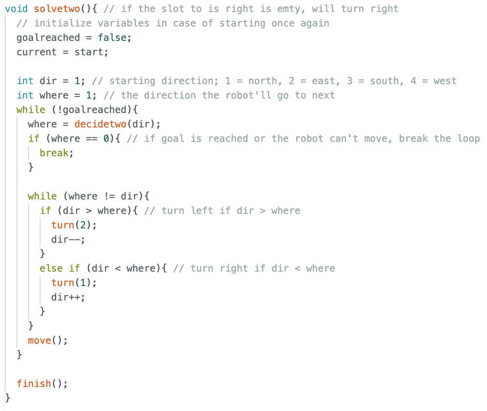
First, I'll add a maze solving program named "solvetwo". This program will basically turn right whenever it can go right.
Solvetwo function:
This one doesn't need a map, so I erased it.
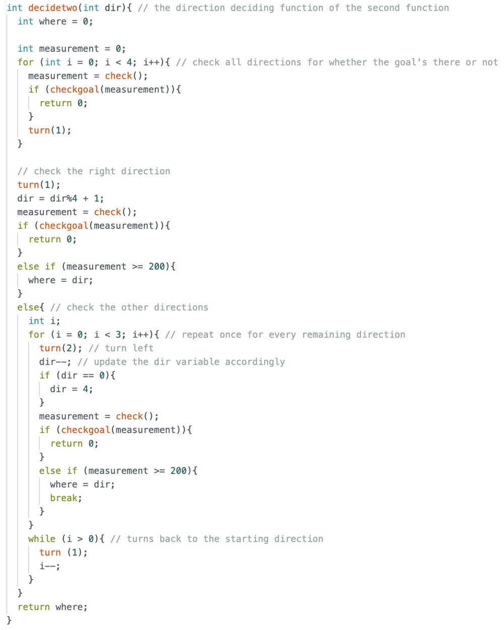
This is the decide function for solvetwo.
Now, I have to separate the start button from solveone and make a menu to select the maze-solve program.
I started by adding a variable named program and initialized it to 1.
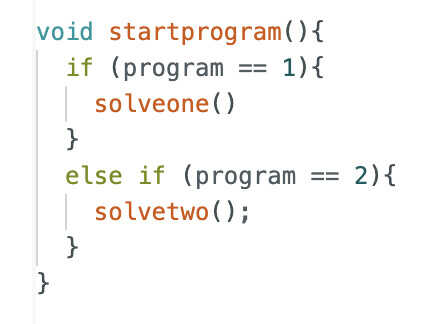
I added the startprogram function and linked the start button to it.
I added this button <button onclick="window.location.href='/select'" style="background-color: green; color: rgb(37, 188, 37); cursor: pointer; border: none; align-content: center; font-size: 60px; text-align: center; border-radius: 20px;">SELECT PROGRAM</button>, which is for selecting a maze-solving program. This button calls the selectprogram function.
This is the selectprogram function:
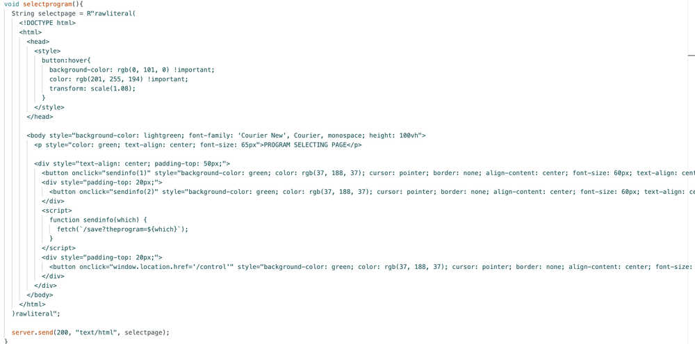
I updated the save function accordingly.
With this, my code is finally finished!
Files
Here is the full program code.
Carrier-Bot | Advertising | Update 8
Info About the Update
This update is about creating my vide and poster and working on system integration since the cables of my robot are a big problem right now. I also mentioned which license I chose in this update.
Table of Contents
- License
- Cables
- Video
- Poster
License
This work is licensed by CC BY-SA. You can find the license in my repository.
Cables
I started by shortening the cables of the batteries.
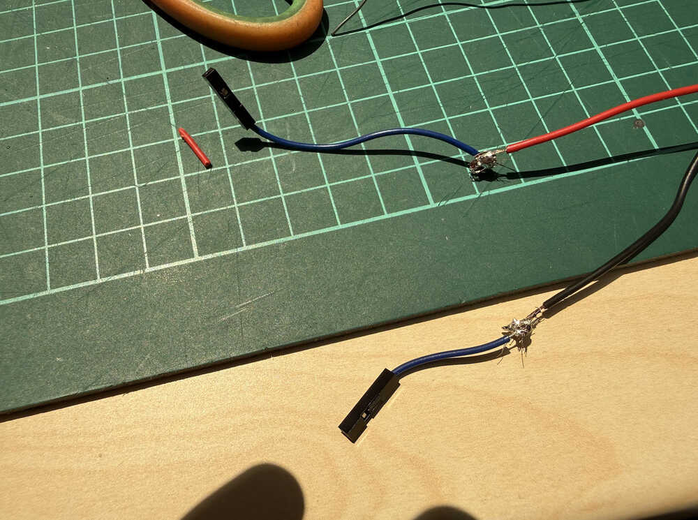
Then, I used this tape to prevent the two from touching each other and destroying the cables (and maybe my board).
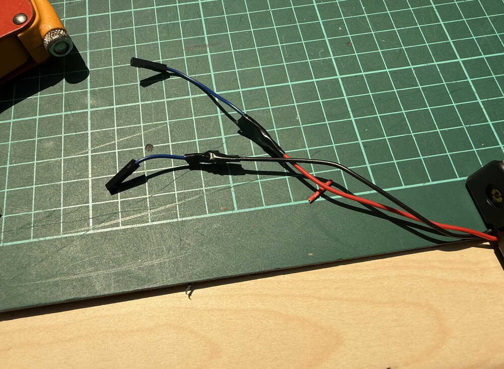
Next, I shortened the cables of one of the servos.
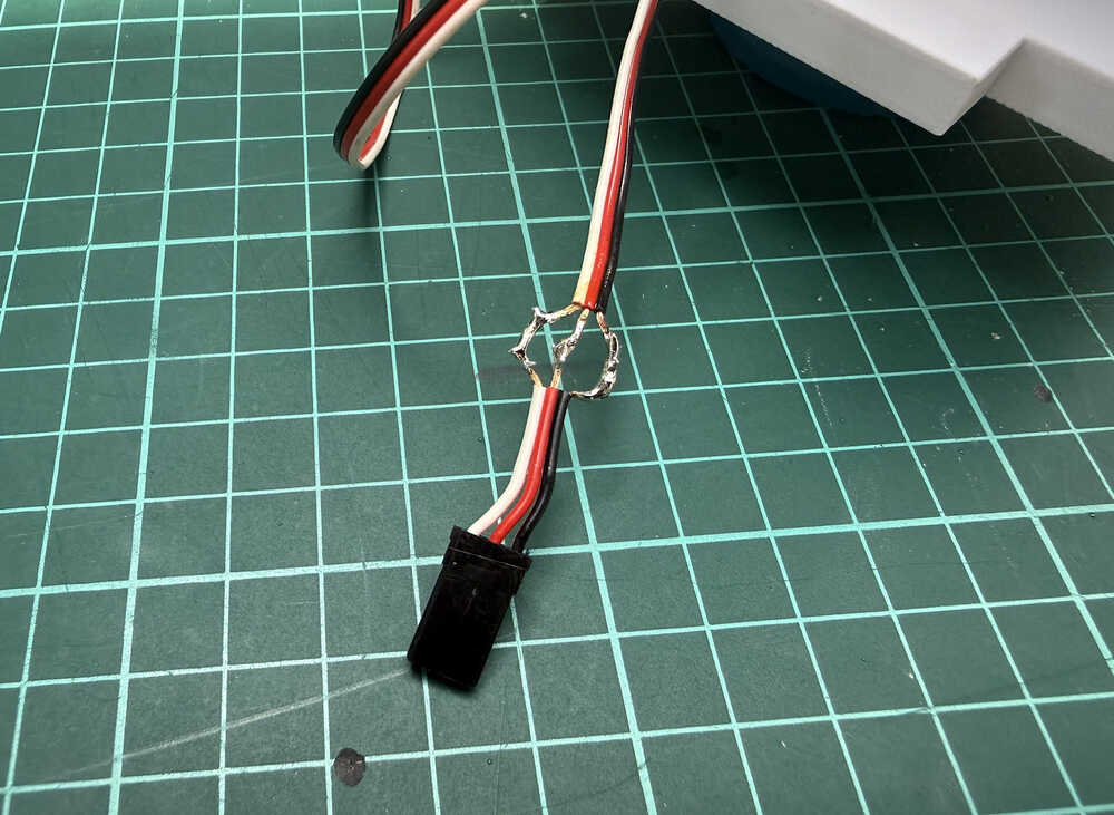
I taped the middle to prevent the sides from touching it.
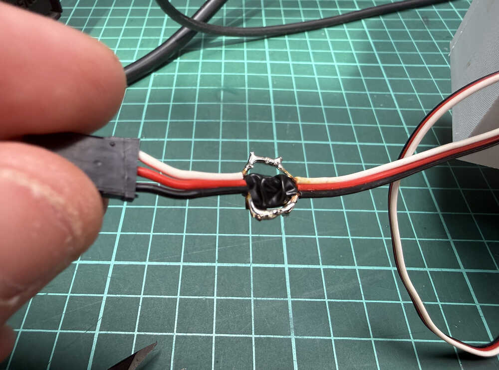
I taped the three cables together.
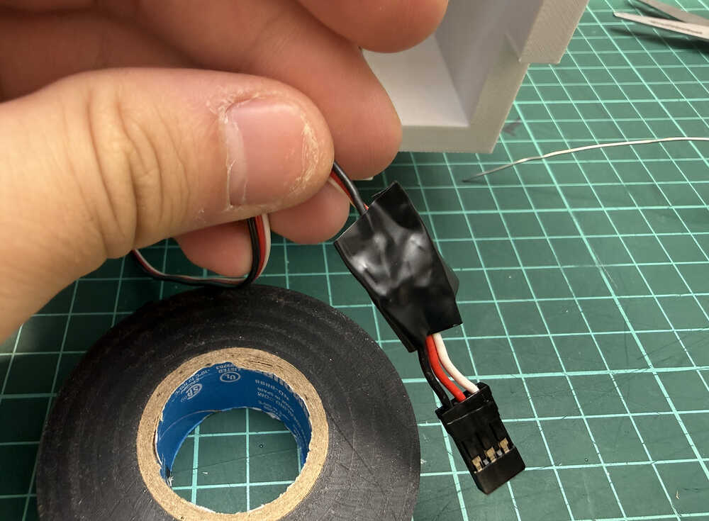
I repeated the same procedure for the other servo, too.
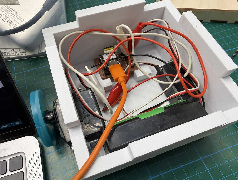
This is how the cables look like right now.
Now, the robot's cables are actually safe and proper. Also, I tested it, too, so I know that I didn't accidentally destroy my servos.
Video
After connecting to the powerbank, the powerbank lost its power a few seconds after connecting. I solved this problem by lighting the LED on the robot. I also wrote turned off the sleep modes. I also soldered a 200 ohm resistor between the 5V pin and the ground. I won't be adding these to my documentation any more than this since this was a problem I personally faced because of the powerbank I bought, and is not needed for reproduction of the product.
Also, my PCB stopped working at some point while creating this video (maybe there was a short or something, couldn't find it), so I had to make a new one.
This is the video!
Created in CapCut.
Poster
This is the poster!
Created in Canva.
Carrier-Bot | The End | Update 9
Info About the Update
This update is about finding one or more materials that can be used to make the robot detect the goal.
Table of Contents
- Goal Material
Goal Material
I started by asking ChatGPT I have a VL53L0X ToF distance sensor. I'm using the VL53L0X.h library to write my code. What type of material can make it so that a distance of about 50mm reads higher than 2000mm?.
I got this list of materials:
- Black velvet
- Black flocking paper
- Black felt
- Optical light traps
- Polished aluminum
- Mirror glass
- Chrome surfaces
Basically, the list is focused on materials that either absorb a lot of IR light or materials that reflect the light at a different direction.
I prefer black velvet since it is easy to find and I actually have some.
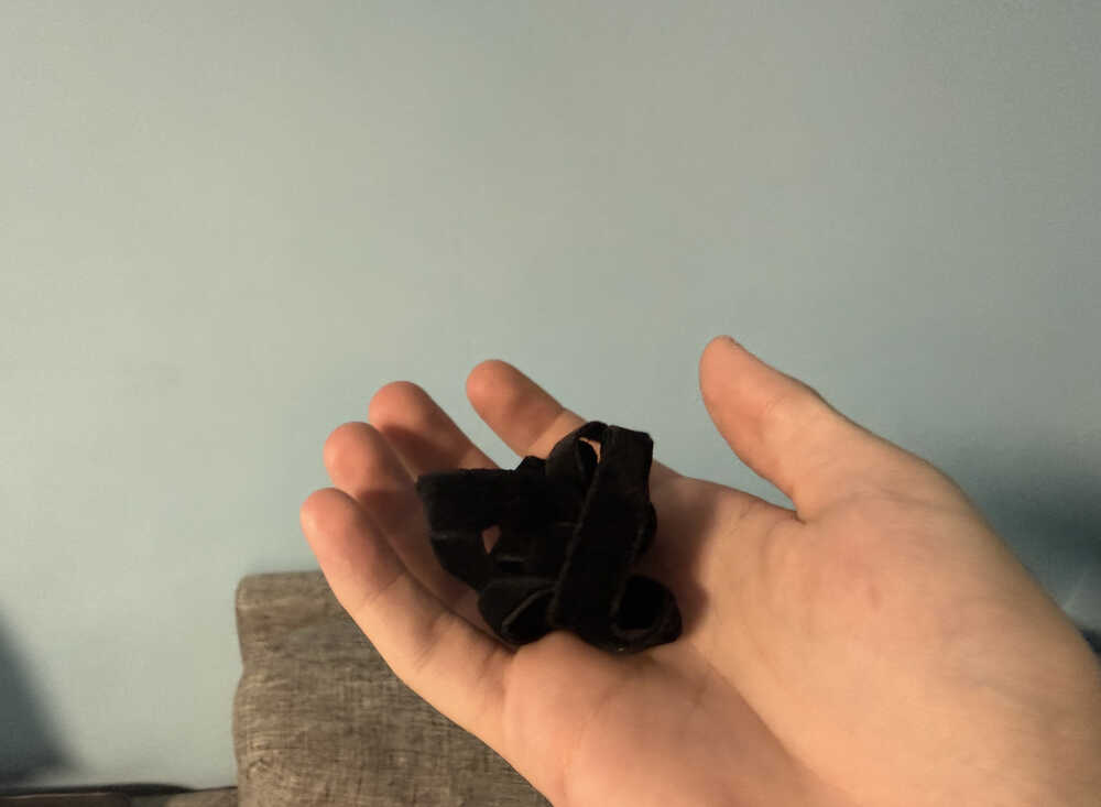
Also, with such a material, I wouldn't need to put the material in an angled way. If someone is looking to replicate this project, they should use one of the materials below (or something similar):
- Black velvet
- Black flocking paper
- Black felt
Final Words
Fab Academy has been a really good experience. Through the end, because I wasn't caught up, I had to work a lot to catch up; however, I was able to finish my work, so I'm quite happy. Also, generally, I had fun while creating the robot.
I liked most of the things except moulding and casting since, even though they're fun, they tale a lot of time, which is why they're kind of in the middle in terms of likeness by me. I also didn't really like designing the 3D part of the enclosure (although I usually like designing in 3D), it was kind of boring for me. Something I really didn't like was adding clearance. I mean, creating a 3D design with clearance meant that I had to re-print the whole thing if I wasn't satisfied with the current looseness. Also, clearance's relation to looseness gets affected by the thickness of the walls etc. and the size of the material you're using, so you either get lucky or experiment with different clearance values, which takes time for such an unimportant reason.
All in all, I'm really glad I joined Fab Academy. I learned a lot and gained a lot of new skills.