CNC
Group members
Toolpath generation
For this weeks group work our instructors Juha-Pekka Mäkelä and Auno Latvalehto had prepared a demo part to be machined on a Haas CM-1. The toolpath generation was done in Autodesk Fusion. The part had a flat face with rectangular pocket with filleted corners. It also had four holes that would be threaded for M4 bolt. Tooling loaded to our Haas, were added to the Fusion via the Tool Library.
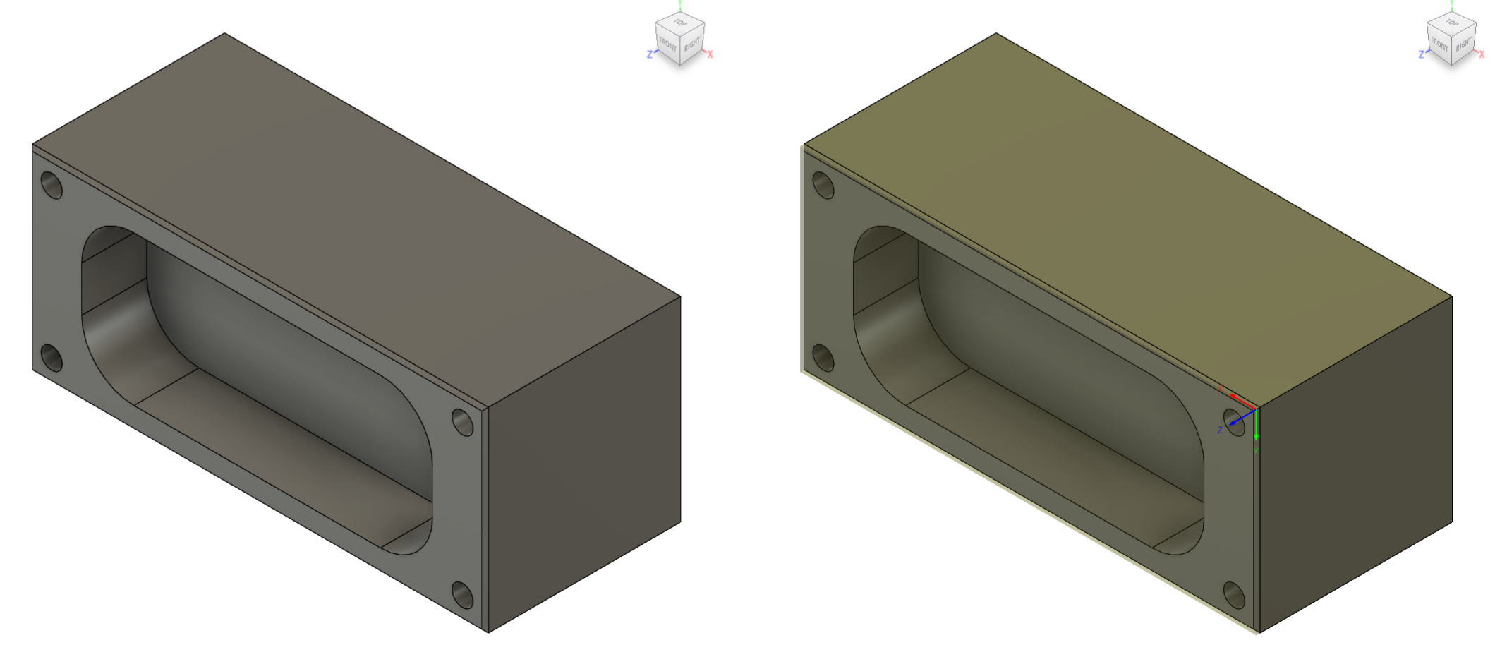 Demo part on left and demo part with stock and origin set on right
It was explained that it is important to model the stock as closely to the real life stock as possible. This done so the machine wont crash in to the real life stock. The origin is easiest to set to the top of the stock and in the left corner closest to the Haas CM-1 milling machine door. The stock was set to be 0.1 mm higher than the part.
First operation was facing the 0.1mm from the stock. A 7 mm flat end mill was used in this toolpath. To face the whole stock you don't select anything in for the geometry.
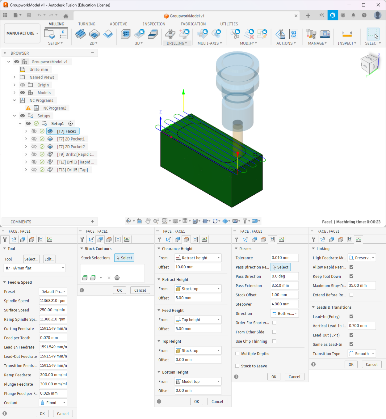 Facing toolpath and it's parameters. To face the whole stock don't select anything as geometry
For pocket roughing the bottom face of the pocket was selected as geometry. Multiple depths option was used to keep the cuts lighter and 0.5 mm of radial and axial stock was left for finishing pass.
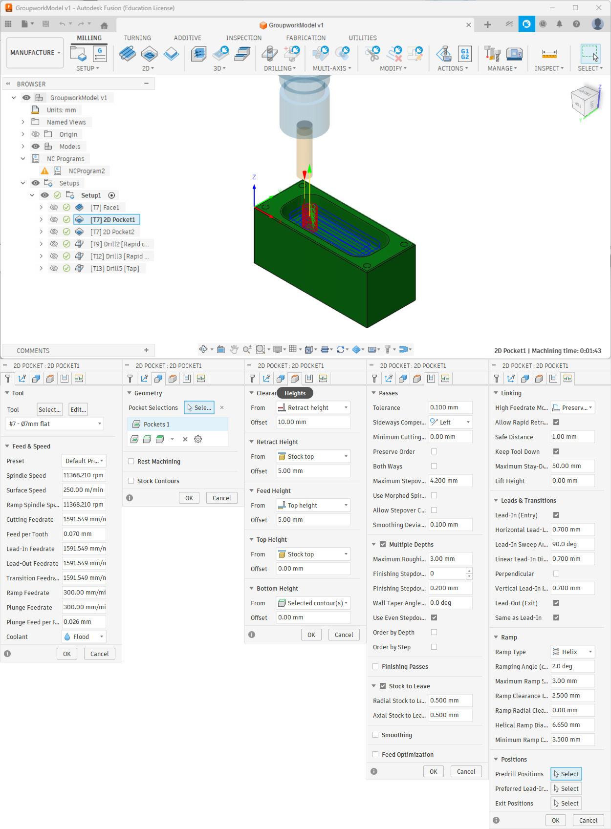 Pocket roughing toolpath and it's parameters. It was done in multiple depths. 0.5 mm of radial and axial stock was left for finishing
Finishing pass for the pocket was the same as roughing but Stock to Leave and Multiple Depths were turned off
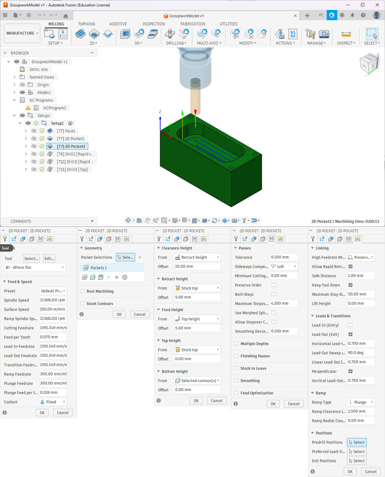 Pocket finishing toolpath and it's parameters*.
For spot drilling 8 mm 90° spot drill was selected as a tool. Holes were used as a geometry. Bottom height was set to -1.5 mm from the hole top.
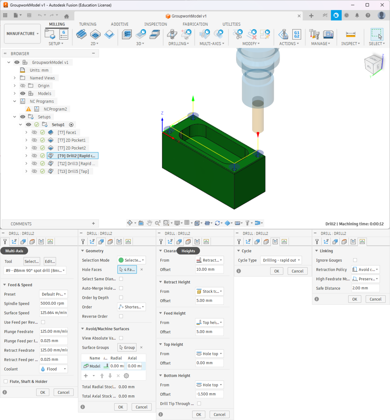 Spot drilling and it's parameters. Bottom height is set to -1.5 mm from the hole top
3.3 mm drill was used as a pilot hole for M4.
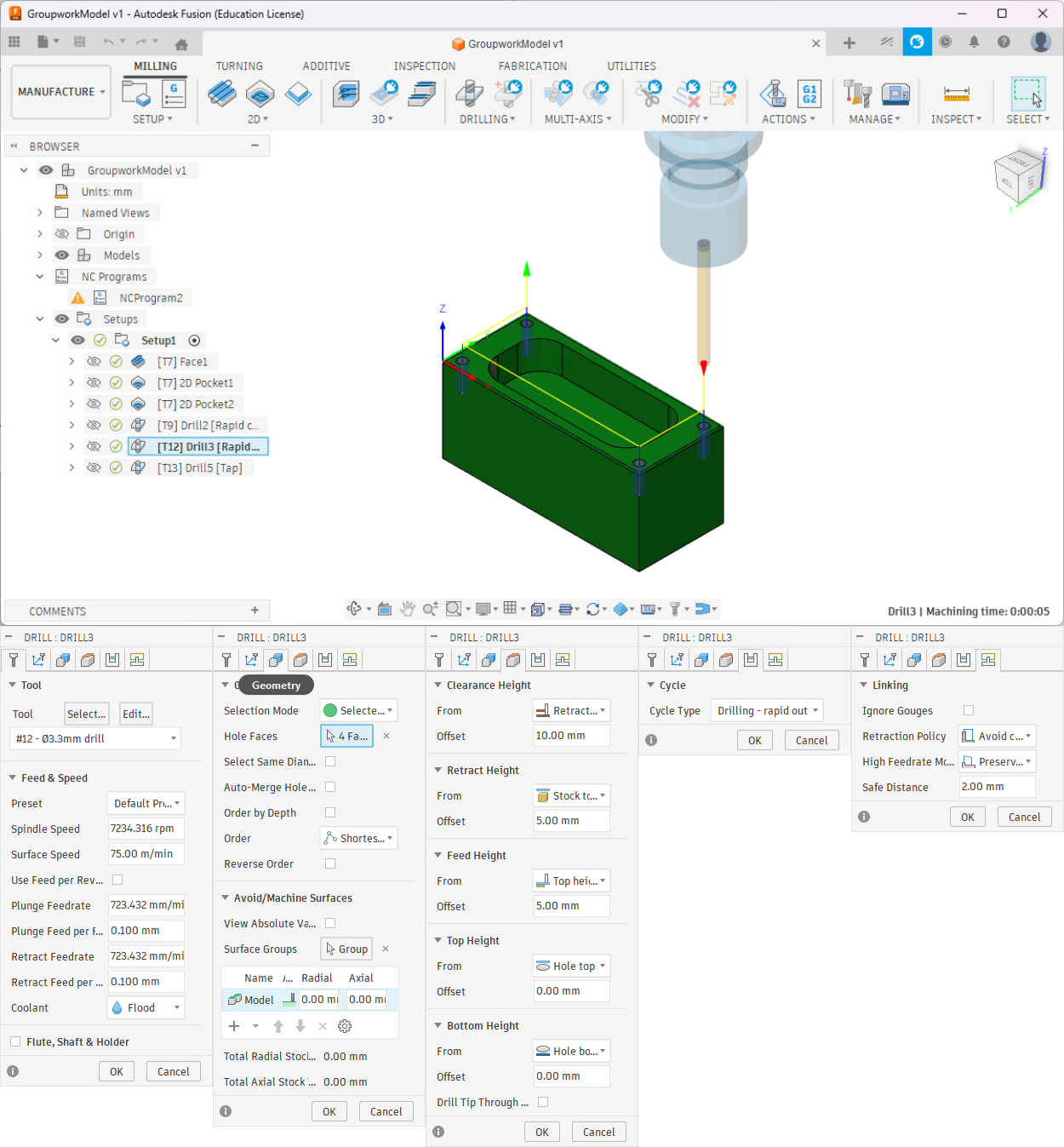 Drilling and it's parameters
For tapping M4 tap was used. The RPM was set to 300 RPM.
 Tapping and it's parameters
Then the toolpaths can be simulated and verified that there aren't any error or crashes.
Then the toolpaths are postprocessed and exported as NC code.
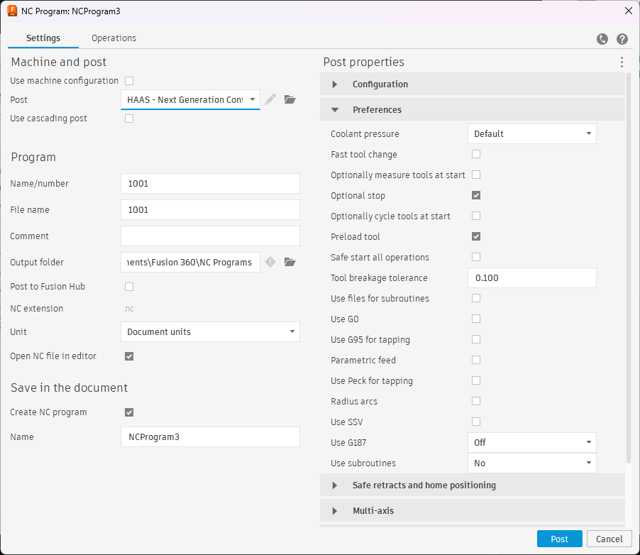 Post process
Machining
The milling machine that we used is a Haas CM-1. It has 30 000 RPM spindle and 20 tool tool changer. Quote from their website:
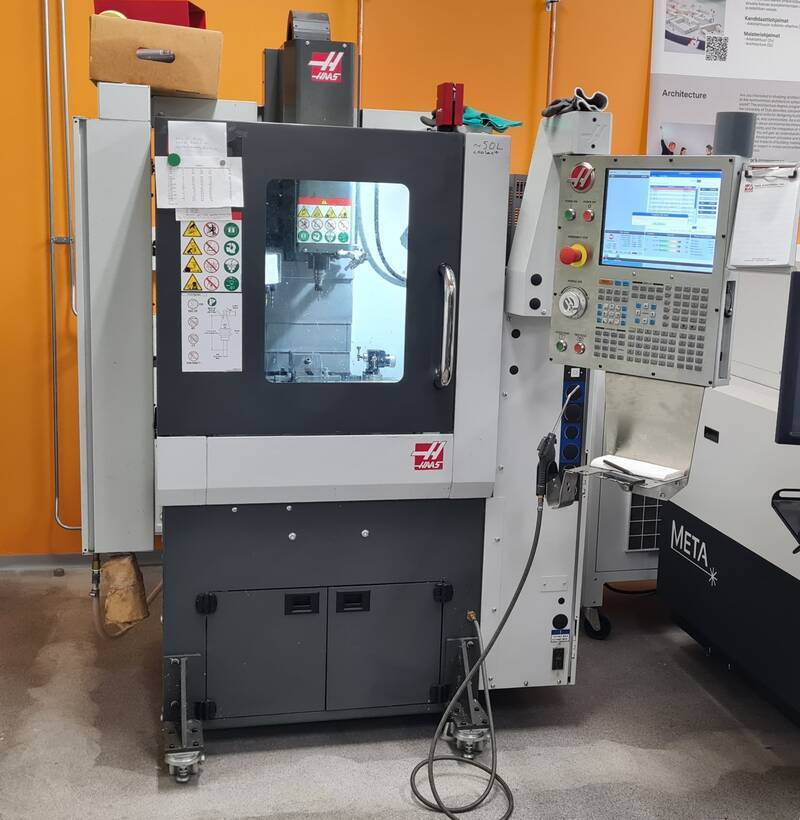 Haas CM-1
The spindle needs to run through a 20 minute warm up period if the machine has been unused or turned off for 2 hours. Auno and Juha-Pekka had done this before the lecture.
First step was to mount the stock to the vise on top of suitable parallers. When important thing to look when tightening is to see that the vise bolt is tightening in roughly 45° angle. If it isn't, then you need to change the position of where the clamping mechanism is located.
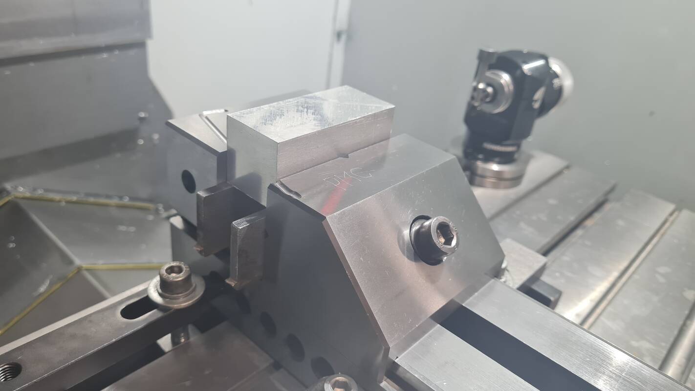 Stock on top of parallers and in a vise
To set the work offset a Renishaw probe was used. It isn't stored inside the tool carousel, so it stays clean. Still a position 20 is reserved for it in the carousel. To mount it you hold it against the spindle and press the tool release button on the control panel. You remove it the same way and you need to hold the probe firmly so it doesn't hit anything while being pushed out.
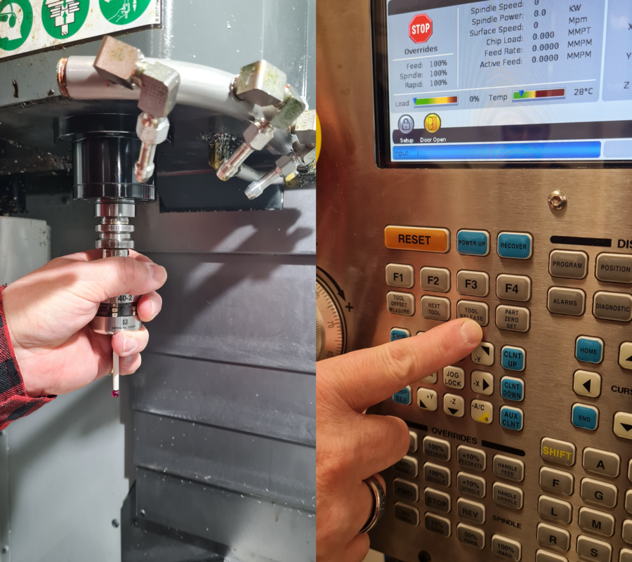 To attach the probe hold it against the spindle and press
 TOOL RELEASE
Origo was set for each axis separetly. For probing the probe needs to be moved close to the stock, about 10 mm from the direction you want to probe. First HANDLE JOG was pressed to enter the jogging mode, then the step size was set to .01. After that the axis and direction of it can be chosen. Then the HANDLE JOG wheel could be slowly turned to see if you are moving in the direction you wanted. It is good practice to start with a slow and short move to confirm that you are moving in the right direction.
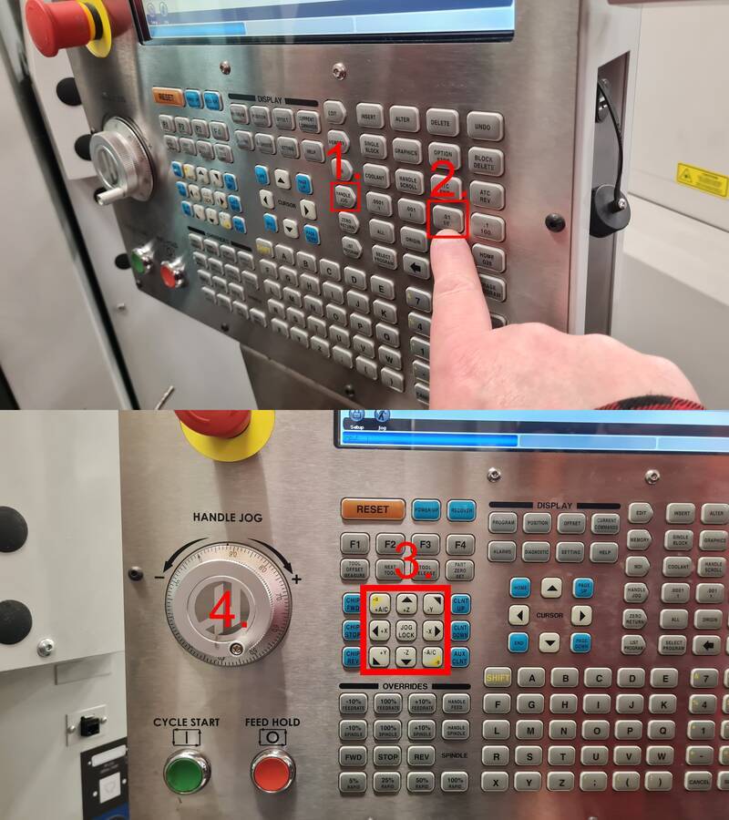 Jogging
First the probe tip was moved about 6 mm on top of the stock to probe for Z. Then in the offset menu G54 work offset was chosen. Then by pushing F3, you can get to probe action menu. From there a Single Surface was chosen.
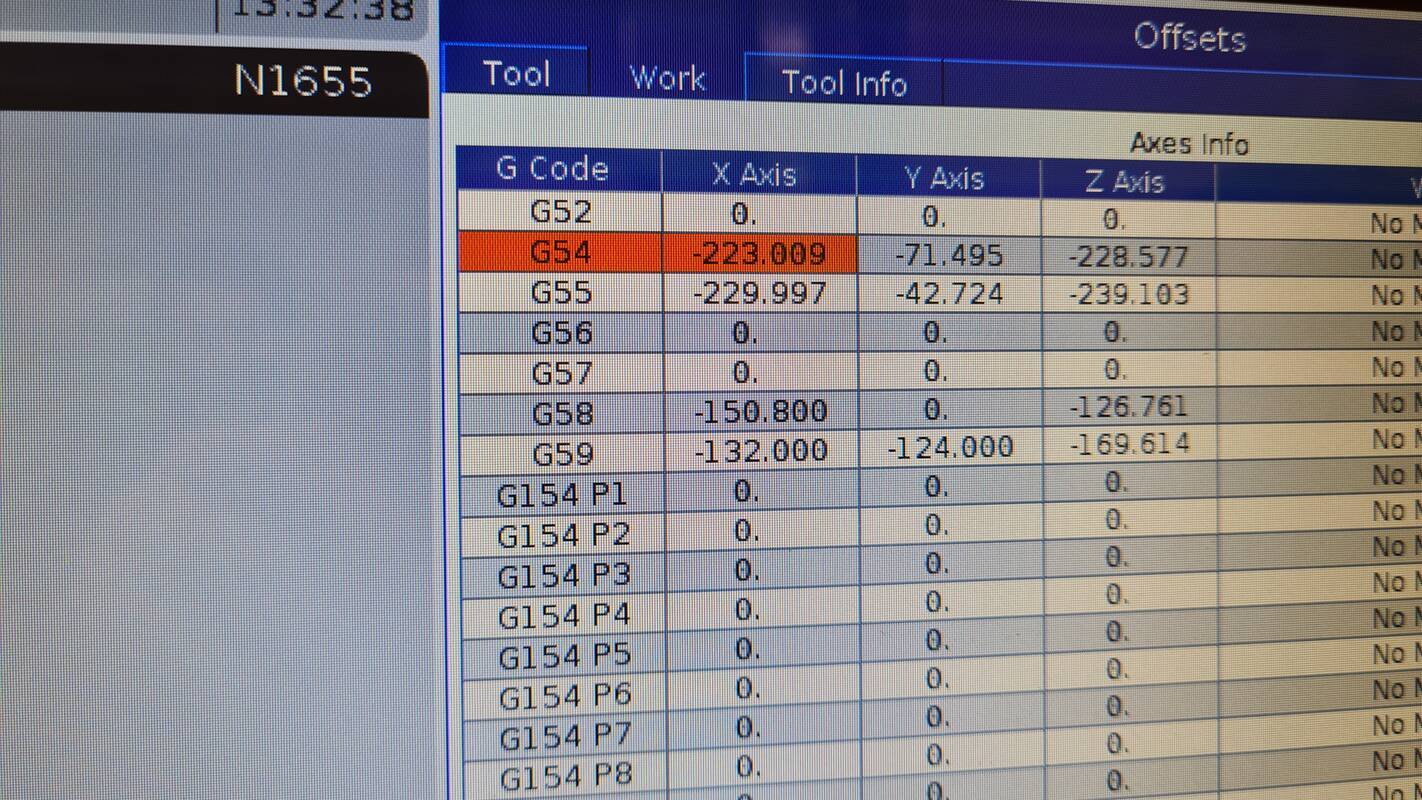 G54 work offset
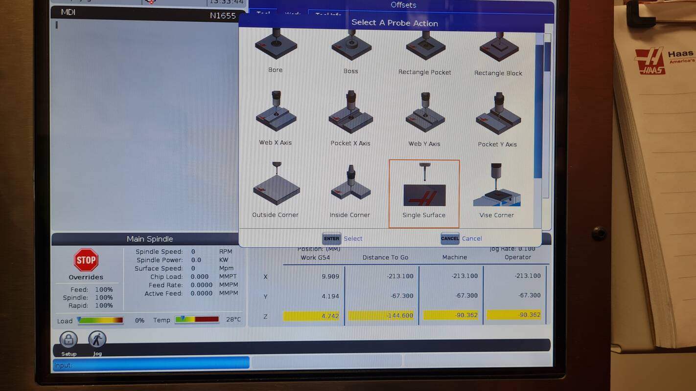 Single Surface probe action
To probe a single surface, Z axis was chosen by inputting Z in the SELECT_AXIS field. Then -6.0 was given as Z value.
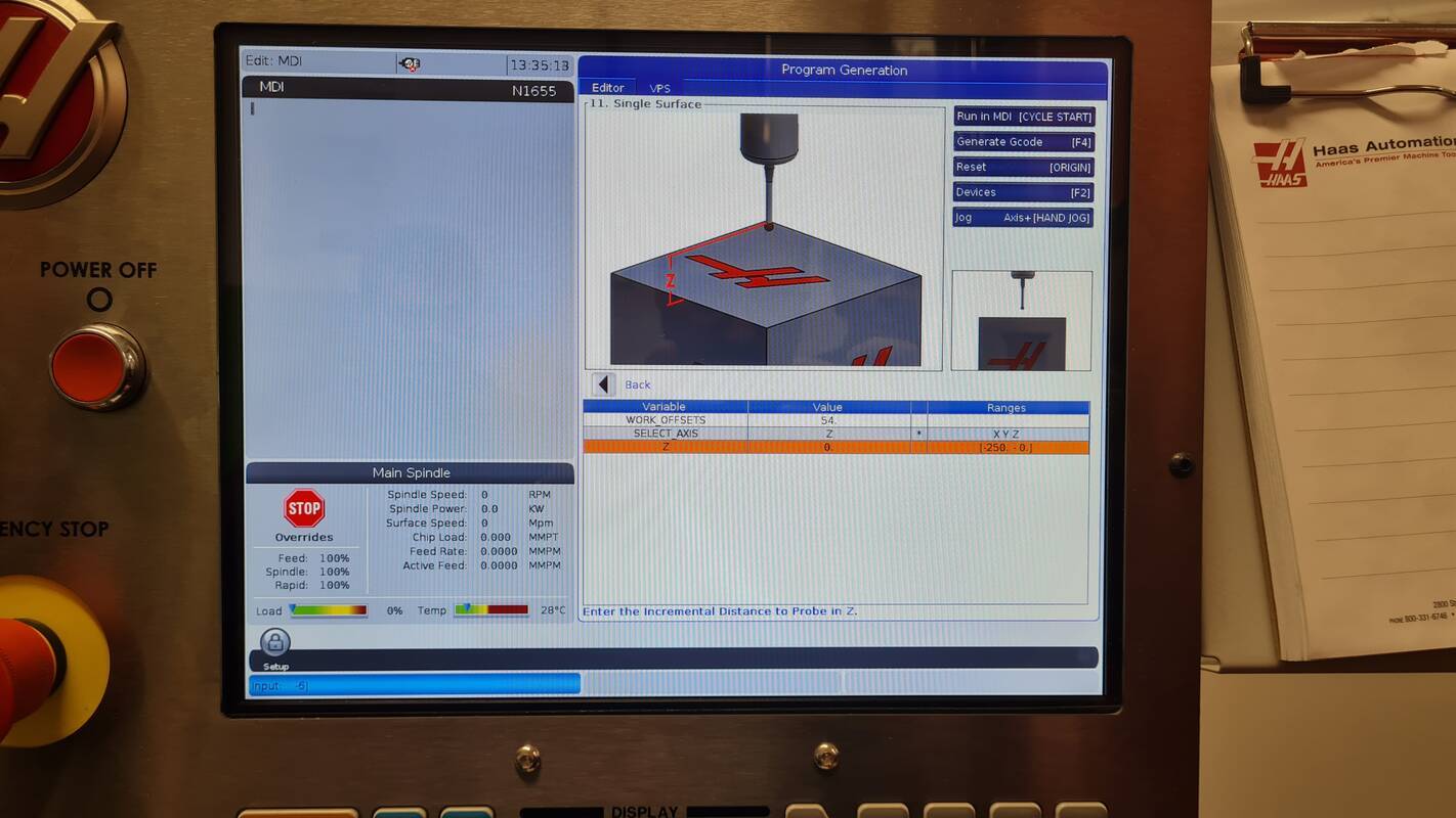 Z as axis and -6.0 as Z value for program generation
Then CYCLE START was pressed to run the probing program for Z. Same process was repeated for X and Y axises.
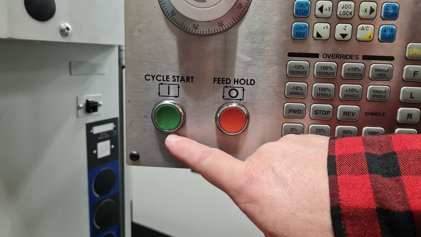 Cycle Start to run probing
After work offset was set to correct position by probing each axis, the NC program that was genarated with fusion could be loaded from the USB-stick. It was done by pressing LIST PROGRAM and going to USB tab. There the correct program called FabLabMAchines.nc was loaded by pressing SELECT PROGRAM.
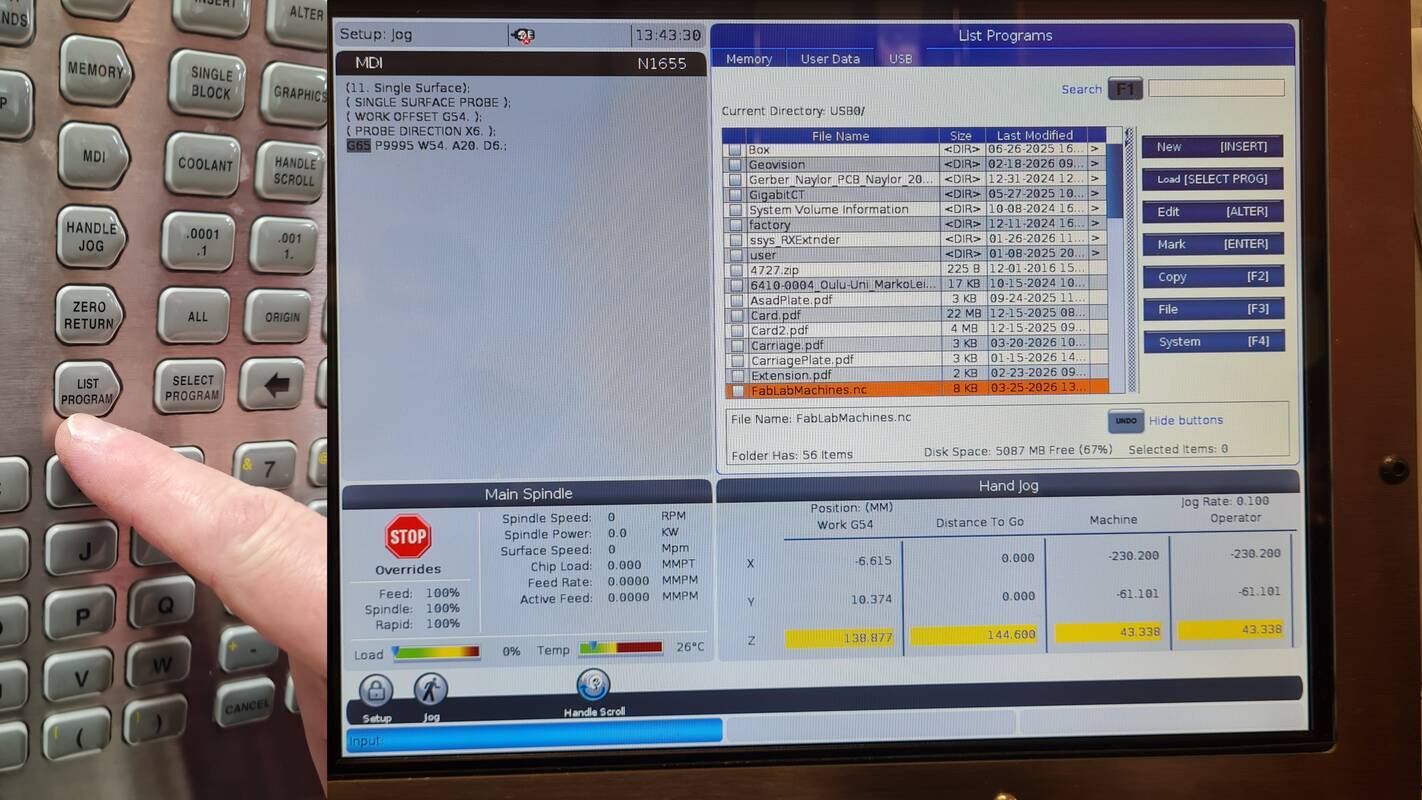 Selecting program to run
Before running the program, rapid movements were reduced to 25% so you have a bit more reaction time to hit FEED HOLD if it looks like the machine is going to crash.
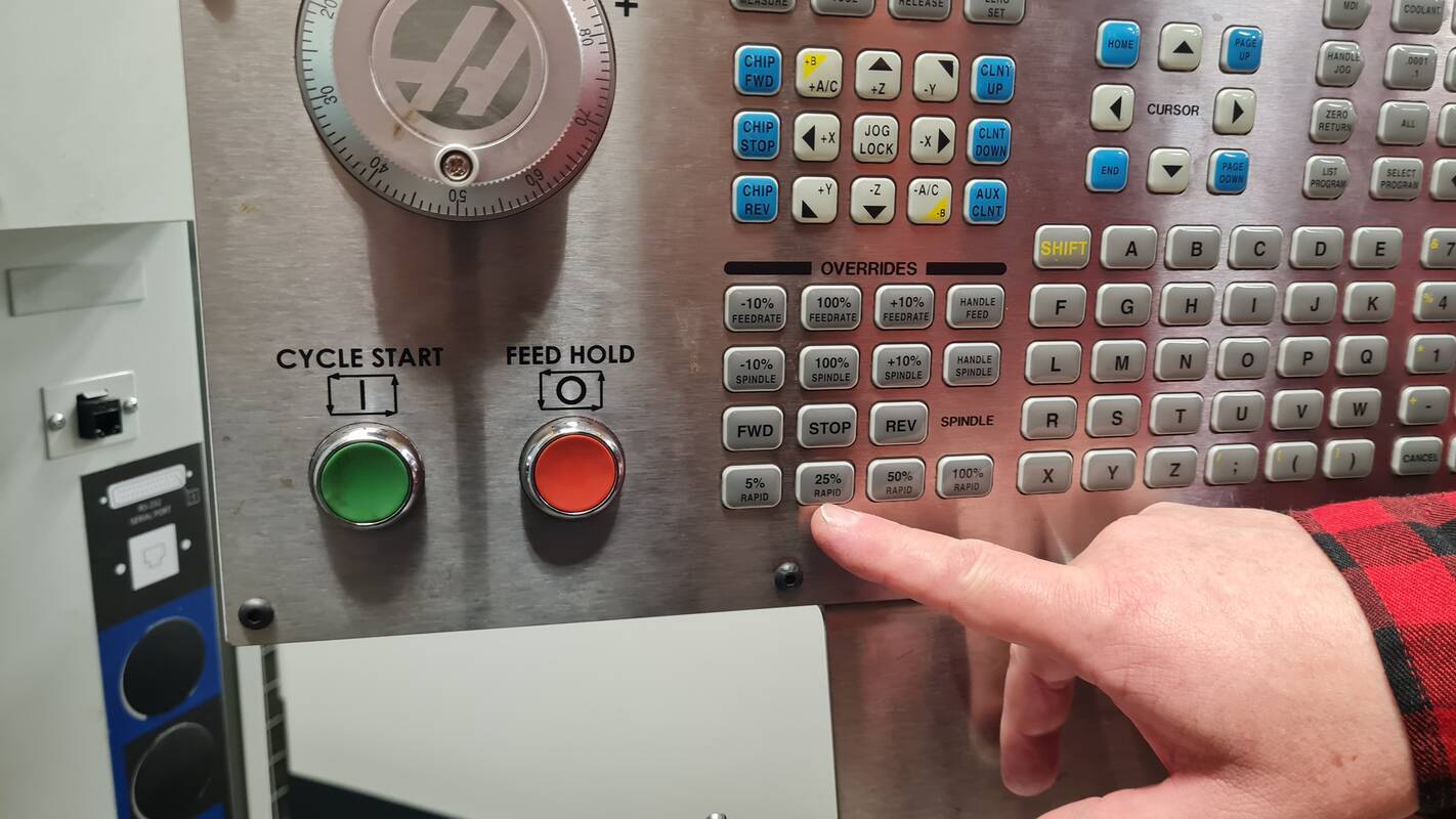 Reducing rapids to 25%
After the program was finished, the chips and coolant was blown off the part. Then the part was washed to get rid off rest of the coolant.
| ⚠️ Warning |
|---|
| Flying chips are sharp, coolant is allergenic and compressed air is loud. Wear proper personal protective equipment. Gloves, safety glasses and hearing protection! |
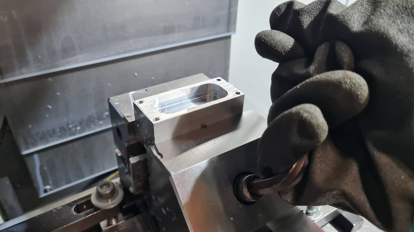 Taking the machined part out of vise after clean up
Then a tool 20, so empty spot for probe, was changed by going to MDI and typing M6T20 and ENTER. M6 is toolchange and T20 is tool in spot 20. Only do this after you have done the clean up so no chips fly into the spindle.
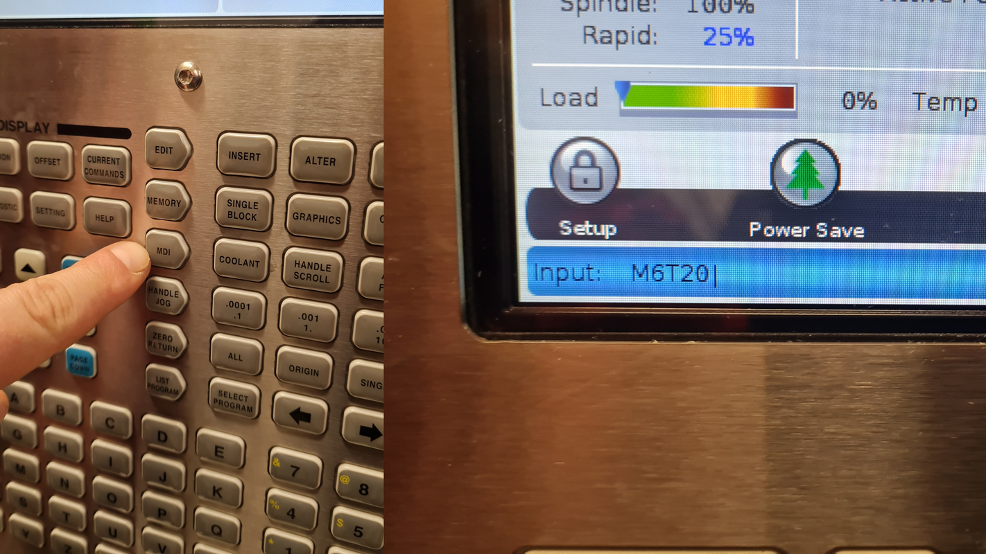 Changing tool to empty spot
Then it was time to finally admire the finished part.
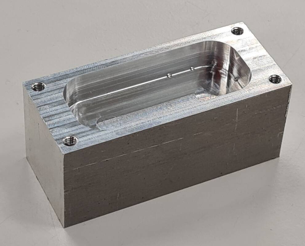 Hero shot.
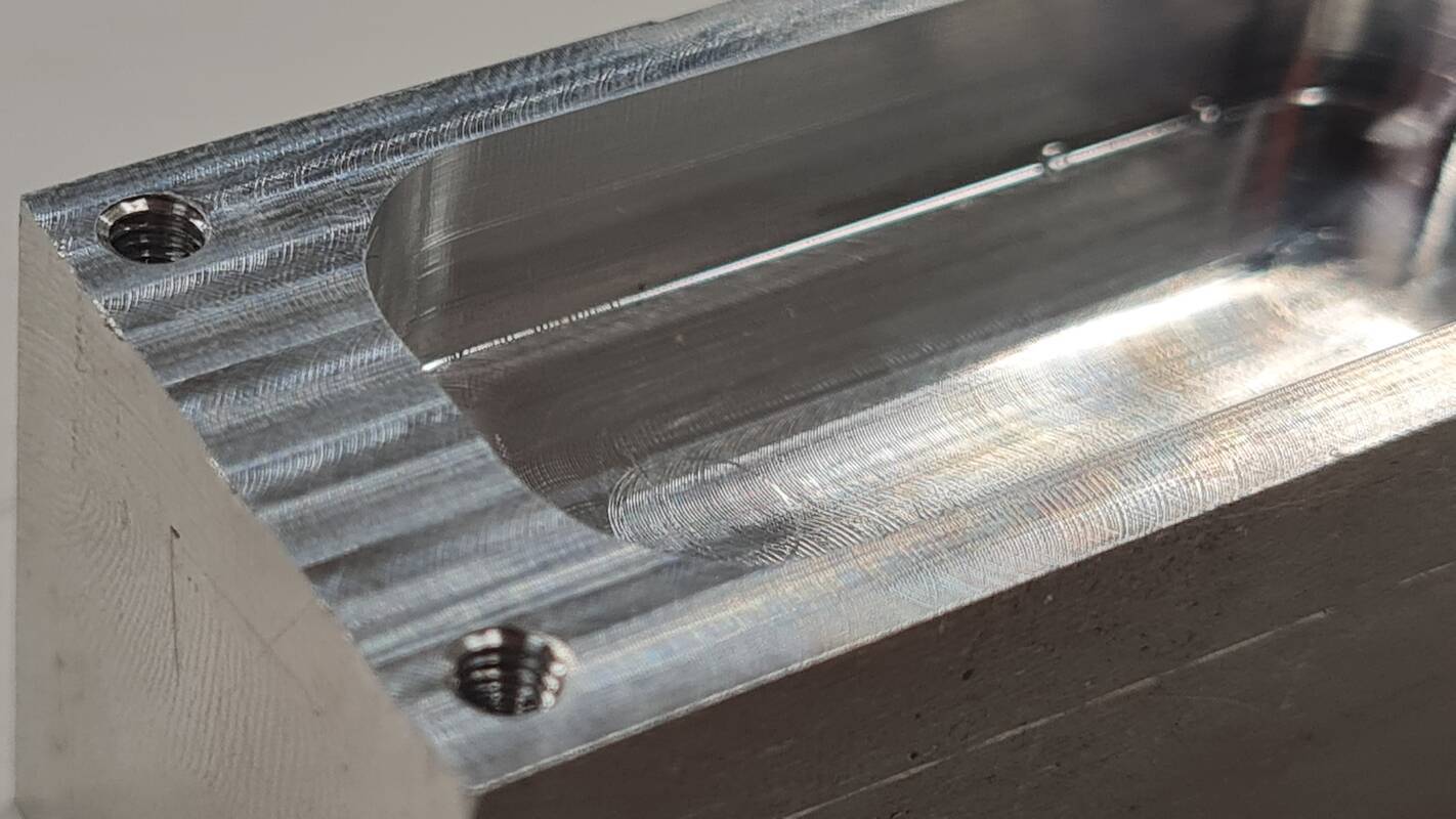 Close-up.
Dimension comparison
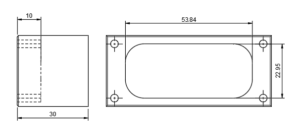 Drawing with measured dimensions.
| Axis | Modeled | Measured |
|---|---|---|
| Z | 10 | 10.03 |
| Y | 22.95 | 22.85 |
| X | 53.84 | 53.54 |
The largest dimension has 0.3 mm millimeter difference between modeled and measured values. That was in the X axis. Y axis had 0.1 mm difference. The closest value was in Z axis where the difference was only 0.03 mm. Possible explanations could be tool wear, measurement error or inaccuracy in the machine itself.