10. Molding and casting

In this week’s assignment, the requirement is to design and mill a mold and then cast it to create a 3D object.
Group Assignment:
- Review the safety data sheets for each of your molding and casting materials
- Make and compare test casts with each of them
Please visit our lab’s for the group assignment.
Individual Assignment:
- Design a 3D mold around the stock and tooling that you’ll be using, mill it (rough cut + (at least) three-axis finish cut), and use it to cast parts.
- Design appropriate objects within the limitations of 3 axis machining
- Demonstrate workflows used in mold design, construction and casting
Design:
The first step is to insert my base measurements to know the dimensions I’m working with
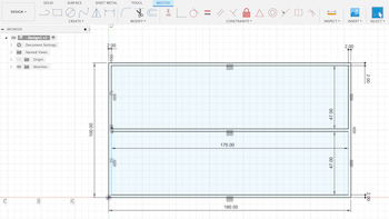
Inserted the joint dimensions and now I have the parameters I’m working in
I extruded the base to 15mm
Sketched my design on the top plane of the extruded surface
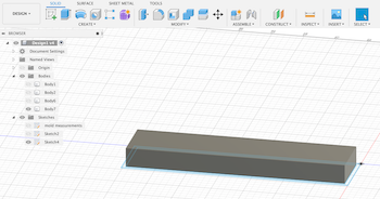
Revolved and extruded the shapes
then combined all shaped to become one
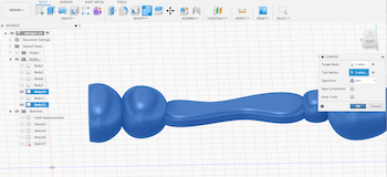
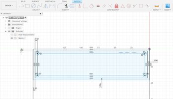
I added the molding material pour spout (pipe) and extruded the joints
Copied the body then extruded the second body joints to -18mm
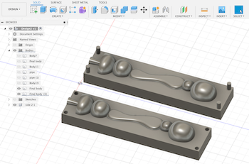
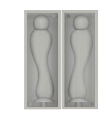
Final design:
CAM:
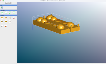
MeshCAM generates a toolpath (.gcode) from an STL or DXF file that we can use to cut our machinable wax.
To begin, I downloaded MeshCAM 6 and imported my STL file. I selected 3 axis cutting option
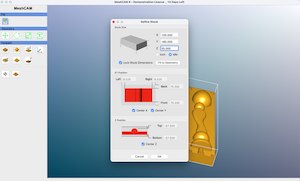
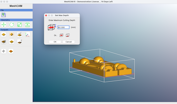
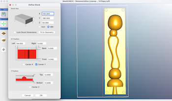
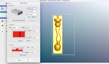
I defined my stock size and centered the X Y and Z positions
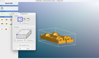
Set the program zero to the top of the stock and upper left side
Set the cut depth based on my design
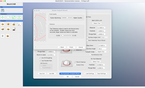
To make the toolpath, I used the automatic toolpath wizard and selected the 0.125 ball tool for both roughing and finishing
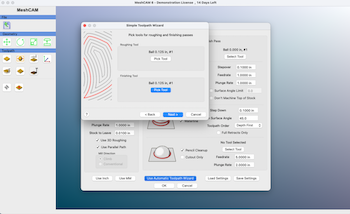
I kept the finish quality at 50% and and a smaller value for tolerance (for higher accuracy)
Clicked ok to generate the toolpath. There was an error and the toolpath wasn’t generated.
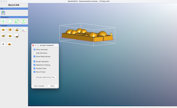
I tried looking up this issue online but didn’t find many resources. I repeated the same process in a newer version of MeshCAM but it also didn’t work. The best option was to try creating toolpaths for each part and see if that helped. I went back to fusion and exported STL files for each part and repeated the process in MeshCAM and it worked!
The only change was to the X position - this is so I can arrange the spacing of my geometry to the left and right of the stock
I created the toolpath, however, the cut time was too much for each piece. to fix that, I went back into fusion, reduced the scale and removed the top sphere. I then went back to Meshcam and repeated the steps above. I created the toolpath again and saved both Gcode files to import in Carbide 3D.
Milling:
To begin the milling process, I imported my Gcode to Carbide Motion, which is the control software used to operate the Nomad CNC machine.
The steps were:
-
I Opened the software and connected the machine cable to the computer. Then clicked on ‘Connect Cutter’ to connect to the machine.
-
After the “initialize” screen appeared, I clicked on the ‘Initialize Machine’ button to begin homing the machine.
-
I imported the Gcode file
-
I went the “jog” tab to move the toolhead by clicking the appropriate arrow button to position the zero. After setting the jog position, I clicked the Set Zero button to zero all the axes, then clicked done.
-
The final step was to go to the run tab and hit start to begin the cutting process
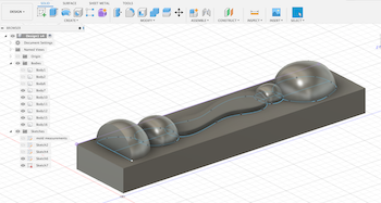
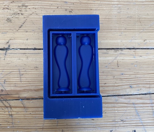
After the cutting was complete, below was the final result.
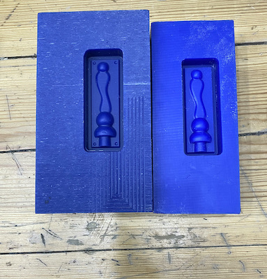
The mistake I made here was not adding a parameters for the 3D shape so the indents in the rigid cast don’t protrude in the flexible mold (making it hard to have a clean cast final outcome). The second issue was that when copying the first body in Fusion, I did not mirror the second body.
Revised Design:
Design:
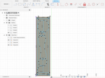
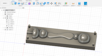
To fix the sizing issue, I increase the overall size slightly, removed the bottom and top sphere, and cut the bottom sphere just enough for a stand.
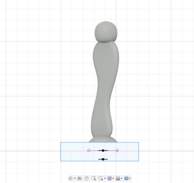
I also added parameters for my design so I don’t run into the same issue. The steps to do this is to create two rectangles around the design, extrude the frame to the desired size, extrude the back, combine the shapes and export as an STL. This also solves the mirroring issue I had previously.
Milling:
I repeated the same steps to get the Gcode from Meshcam and start the milling process using Carbide 3D. Final result:
Casting:
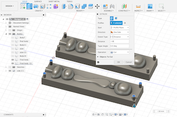
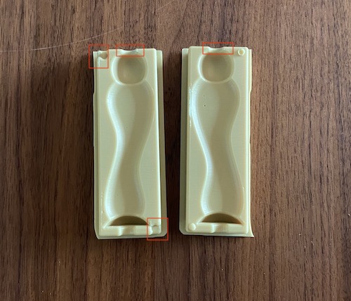
To make the flexible mold, I used Polytek liquid rubber. To prepare the liquid rubber, I mixed part A (Poly 74-Series Liquid Rubbers) and part B (Poly 74-45-Series Liquid Rubbers) as listed in both the instructions and safety + data sheet. When mixed together, they form a flexible and durable polyurethane rubber. I did have some technical issues with the rigid mold that in turn affected the flexible mold, however, it wasn’t necessary to redo the process again. As highlighted below, the negative extrusion did not take the same shape as the original design. I think the issue here was that the parameters around my design were too tight and the mill bit didn’t carve some edges as well. This also applies to the top of the sphere, where there wasn’t a pipe in my design, but looking at the rigid mold it seemed like it was part of the design. I added some tape to prevent leaking when I was casting and it worked just fine! I did get some air bubbles when I was mixing the material, to fix this issue I lightly tapped the container and mold until I saw the bubbles popping.
To make the cast, I used resin from Smooth-On. I mixed equal amounts of part a and b and poured it into the mold, however, I wasn’t able to demold because the resin got stuck to rubber mold. I looked it up online and found that it was recommended to use a spray that prevents this issue from happening. Another possible reason is that I used the rubber mold when it wasn’t fully dry (it was a bit tacky) when I poured the cast material.
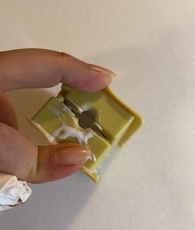
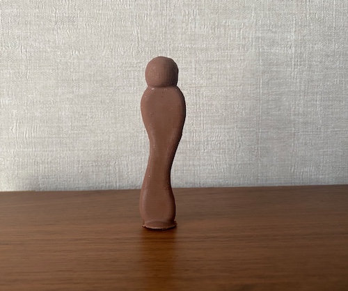
I repeated the rubber mold process again and used chocolate to make the cast.
Process Notes
The overall time it took me to finish this weeks assignment was almost 10 days. The process generally takes a long time for milling, and I did have some mistakes in the beginning where I had to redo my mold. My design was definitely a stress test for the molding and casting process, and while I was considering changing the design to finish faster, I decided to continue and gain a better understanding of the process for the future.
Regarding safety, this week was easier to manage than some other assignments. Important things to keep in mind is that when operating the machine always keep the lid closed, and make sure to be around especially in the beginning. If you hear odd or loud sounds that don’t sound right, then pause and check if there’s an issue with the bit and how secure it is. If the bit isn’t secure, it can break off and break the glass lid.