Assignment 11

Output Devices
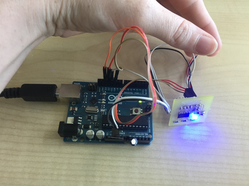


The last week we were asked to gain knowledge about output devices. Of course, an output device can be easy as a LED but gaining knowledge about other output devices is also importabt.

I decided to use the board and photoresistor from the input devices week in combination with an LED for an output device, that will turn on/off according to how much light the photoresistor captures.

Photoresistor and LED
  • After these two indispensable steps I started programming my board. New in this assignment was how to program my board in order that I can use my sensor to detect light. According to the detection I wanted to turn off and on my LED.
  • Code that is flashed on the board.

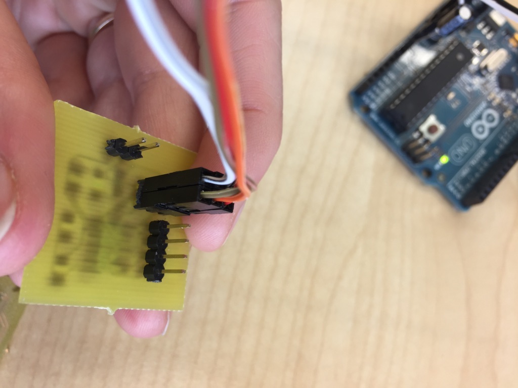
    ISP header of the 'light sensor' board.

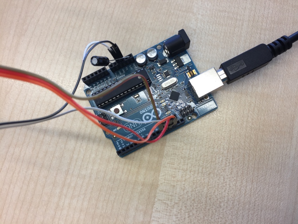
    Cables on the Arduino that is used as an ISP.

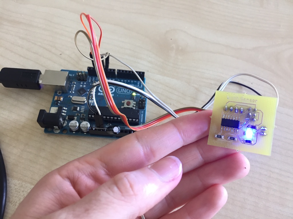
    LED blinks without photoresistor.

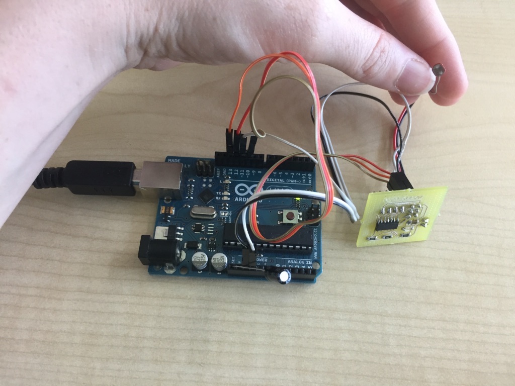
    Photoresistor used to light LED or not. If light is captured by the photoresistor the LED does not light up.

    If photoresistor is covered with e.g. the hand the LED lights up. I want to have this effect in my crib later, as the inside of the crib should be lighted in the evening when it is dark.


    To explain the connection between the photoresistor and the LED here you have the code that was flashed on the board: You can see that photoresistor values of 200-455 are mapped to LED brightness values of 0-255.

                
                    int sensorPin = 7; /*  select the input pin for LDR */
                    int sensorValue = 0; /*  variable to store the value coming from the sensor */
                    int LEDPin = 3; /*  select the pin for LED */
    
                    void setup(void)
                    {
                      pinMode(sensorPin, INPUT);
                      pinMode(LEDPin, OUTPUT);
    
                    }
    
                    void loop(void)
                    {
                    sensorValue = analogRead(sensorPin); //Read data from analog pin and store it to value variable
    
    
                      sensorValue = map(sensorValue,200,455,0,255); // Mapping values of photoresistor to light brightness of LED
                      analogWrite(LEDPin, sensorValue); //Set the brightness value of the LED
                      delay(1000);
                    }


    Waterpump as Output
    For my final project I also build a board that was planned to control the waterpump of my christmas crib for the watering place. You can find schematic and board file of this board in the communication assignment week as I also used this board for a serial-bluetooth connection. For the output assignment I programmed this waterpump board additionally as another output device. Of course, I also followed the described procedure above, which means e.g. burning the bootloader of the attiny45 on the board first before programming it. Underneath you find the code of the Arduino file. for the board.
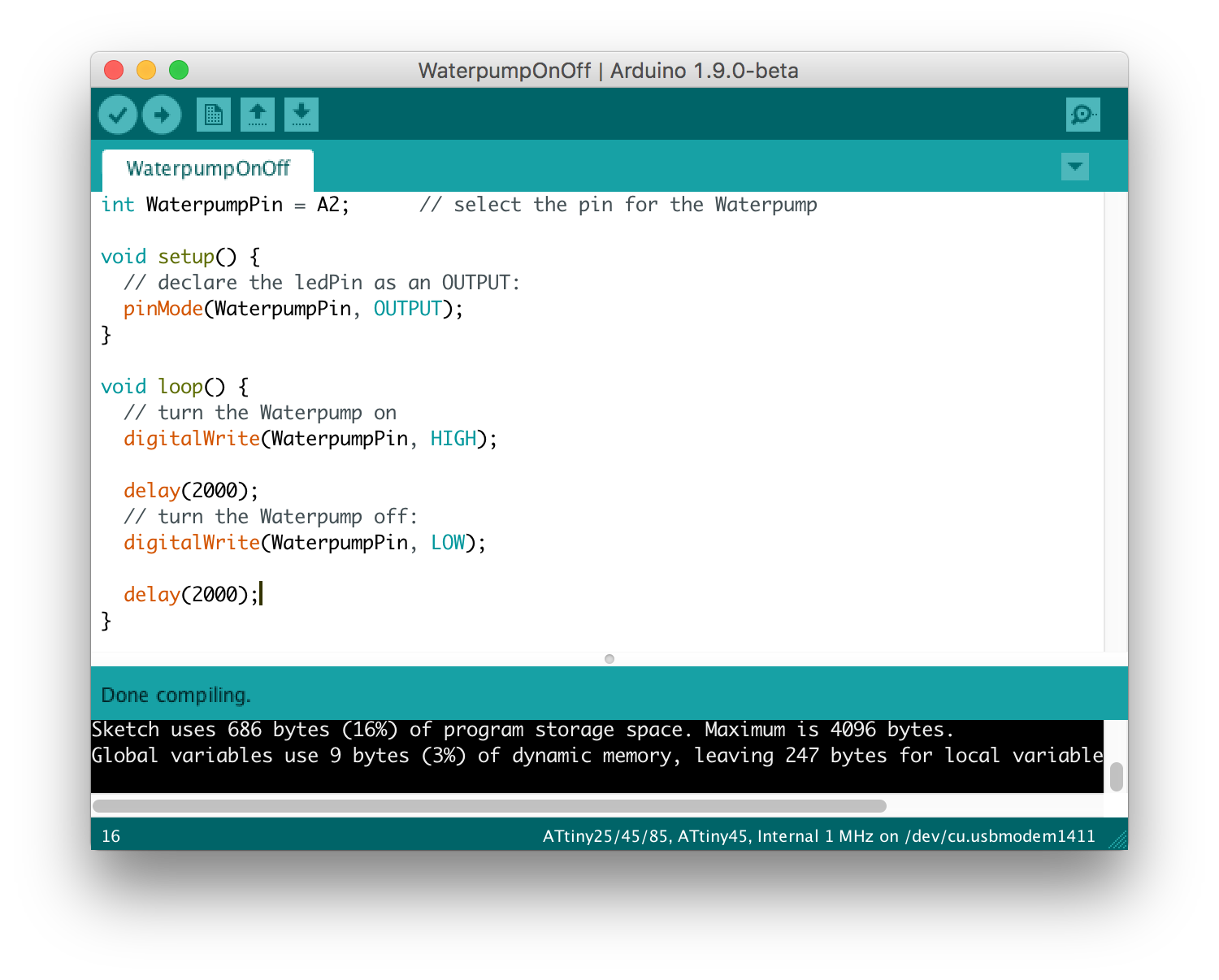
                
                    int WaterpumpPin = A2;      // select the pin for the Waterpump
    
                    void setup() {
                      // declare the ledPin as an OUTPUT:
                      pinMode(WaterpumpPin, OUTPUT);
                    }
    
                    void loop() {
                      // turn the Waterpump on
                      digitalWrite(WaterpumpPin, HIGH);
    
                      delay(2000);
                      // turn the Waterpump off:
                      digitalWrite(WaterpumpPin, LOW);
    
                      delay(2000);
                    }
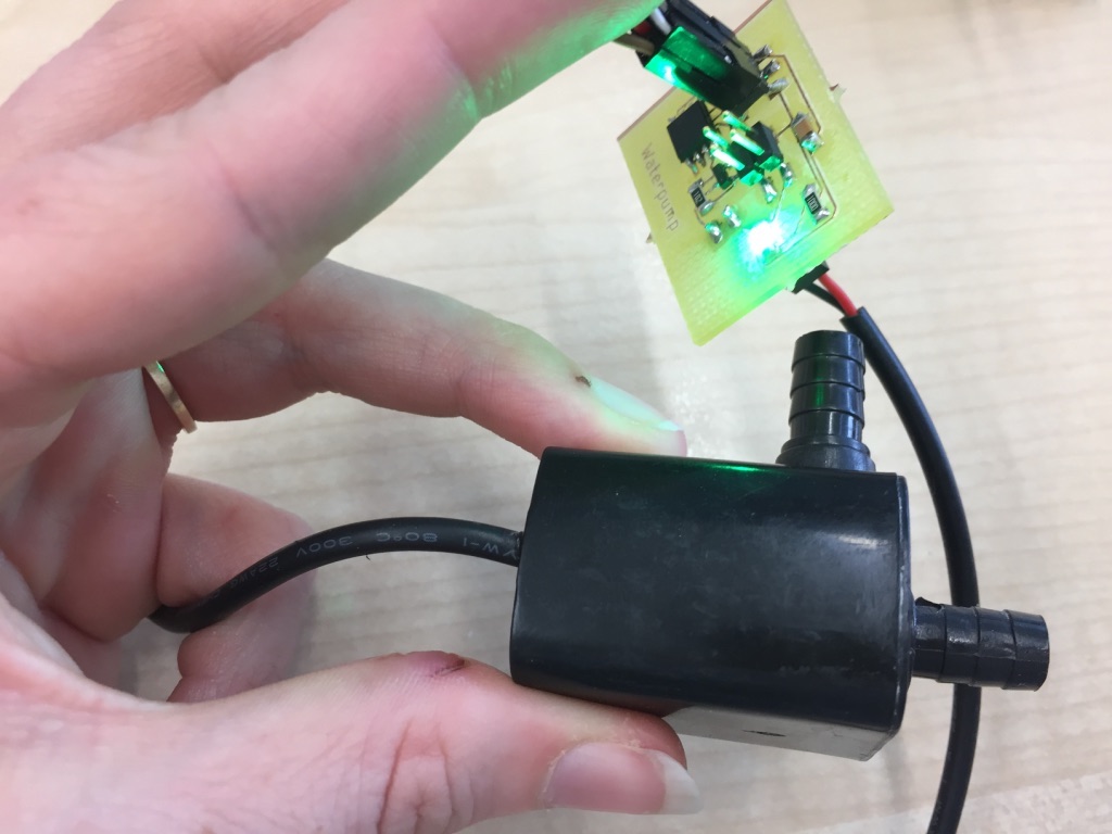


    Waterpump board connected to waterpump.

    Test scenario: Waterpump with green power LED on the right, 3D printed black watering place on the left and waterpump and hose in the middle. I powered the waterpump board using the VCC/GND pins of an Arduino Uno.


    Waterpump board running waterpump with hose that ends in the 3D printed watering place. The watering place has a hole in its basin to let the water out again. This can be seen as soon as water flows into the watering place. The design file of the watering place can be found on the final project page.


    How the Microcontroller Datasheets & Pinouts helped
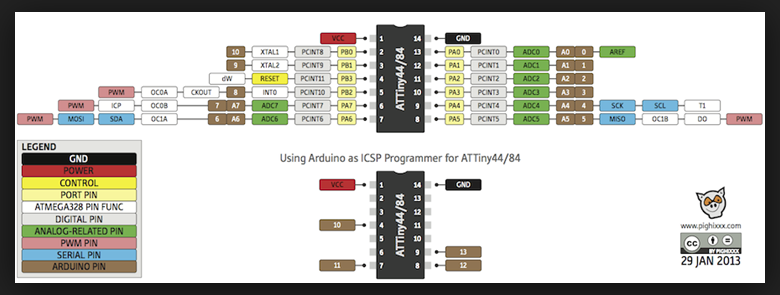
  • The datasheet of the Attiny 44 was helpful in terms of finding out which pin of the microcontroller are MOSI, MISO etc. This was of course very important during drawing the schematic of the board to design the ISP header (Atmel datasheet Attiny44/24).
  • The pinout provided for the Arduino Attiny communication was valuable during the programming with the Arduino IDE. I could find out what is the name of my input and output pin on my attiny 44 board on the Arduino. I know that these pinouts were presumably created by someone in the Arduino community and not official but they are still very helpful.
  • Attiny44 pinout and according Arduino pins.