Presentation
For my final project I decided to make a metronome.
You can check my motivation and project proposal in Principles and practices week.
I explained how it works in the slide I made for it.

Here you can see a little of the process and how also the device working.
Find my full documentation of the process of making this device in my Final project development page.
Final Project
approach
Starting point
I have practice Peruvian folk dance for at least 10 years now, as it is a very important part of my life I decided to make a project related to it.
Peruvian folk has many different expressions and creole zapateo is one of them, it is a musical and choreographic practice in different regions of my country and it is the result of Spanish, African and Indigenous mixture.
I don't love appearing on screen but in this video you can see a little of what I am talking about.
Dance has allowed me to meet a lot of different people with different capabilities and learning abilities.
For this reason, I decided to make a project related to rhythm as it is important to maintain a beat during the performance of a piece. Making some design process and considering my lack of electronic knowledge, but keeping enthusiastic I decided to develop a digital metronome.
Metronome
What is a metronome?
A metronome is a device that produces a sound at a regular interval of time, this sound helps musicians to play their instrument to a regular pulse and keep it throughout an entire song.

Normally the sound of a metronome is similar to a tic or a click, this applies for the analog and also for the digital ones. But for some people it might be a little annoying, or even hard to notice when playing their instrument.
I establishing some guidelines that you can check in my principles and practices page.
Design brief
For this project we needed to design, fabricate and program our own fabbed microcontroller PCB, including an input & output device
This project consists on two parts:
The inside electronics
Microcontroller PCB
Output PCB as the interface
Input device as the interface
Power supplyThe enclosure
A 3d printed, PLA enclosure or case.
Laser cut and engraved top piece for the output
Interface design
Light patron
I decided to design my device according to the possible needs of the user. As music has different rhythmic patrons and subdivisions I designed a central element which is the most important and 6 others around it. Each of them works separately.

Vibration
The vibration works along with the light, each time the center element lights up, the vibration also activates, either we are using the subdivision of the par or not.

ELECTRONIC DESIGN
microcontroller
After sketching my device and how the interface would work, I defined the output and input devices.
Input
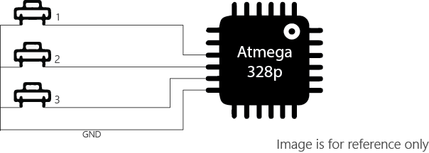
I am going to be using the buttons, as you can see in the diagram below, these three buttons will need three input pins and one connection for the GND.
Output
I am also defining seven different group of LEDs, that means seven input pins and one GND connection.

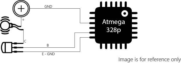
Lastly for the vibration motion, I am going to be using a coin vibration motor, it will need just one output pin but also a transitor and a power source.
Microcontroller pins
Summarizing, the quantity of the devices that need to be connected to the microcontroller is something to be considered. The atmega328p is High performance, low power AVR® 8-bit microcontroller with the necessary capacity to achieved the objectives of this project.
Component |
Supplier |
Qty |
Cost |
|---|---|---|---|
MCU - atmega328p |
Fab Lab Tecsup |
1 |
USD 1.38 |
20 MHz resonator |
Fab Lab Tecsup |
1 |
USD 0.30 |
Switch push button |
Fab Lab Tecsup |
3 |
USD 0.74 |
Battery lithium 3v coin 20mm |
Local supplier |
2 |
USD 1.50 |
Vibration motor |
Local supplier |
1 |
USD 1.2 |
Coin cell holder |
Local supplier |
2 |
USD 2.84 |
SMD LED - white |
Fab Lab Tecsup |
25 |
USD 8 |
1ohm Resistor |
Fab Lab Tecsup |
7 |
USD 0.20 |
10k Resistor |
Fab Lab Tecsup |
1 |
USD 0.01 |
0.1uF Capacitor |
Fab Lab Tecsup |
1 |
USD 0.05 |
Material |
Supplier |
Qty |
Cost |
PLA |
Fab Lab Tecsup |
10 gr |
USD 0.74 |
Acrylic 2 mm |
Fab Lab Tecsup |
50x50mm |
USD 1.43 |
Total cost |
USD 18.39 |
PCB DESIGN
Electronic structure
Knowing the components needed and the limited space to fit everything it is important to understand the structure I need to follow to make everything work together.
Here are the pieces I need to achieve.
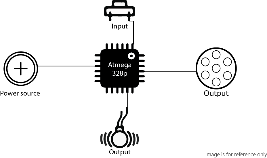
Having this, I decided to fabricate two PCB boards. One with the atmega328p (the brain) and another one for the light output.
LED board
Now for the LED circular array, I connected a 1 Ohm resistor for each group of 3 for the outer part, and 1 resistor for the seven LEDs on the inside part. Each part have a pad for the connection with the microcontroller and one ground pad for all the board.
If you want to try make an array like this you can check output devices week.
I created a 3D from the eagle files, I followed some tutorials on how to create a managed library and some others I found in the youtube channel of EAGLE AUTODESK.
Mother board
As I explained before the atmega328p needs a 10k Resistor connected to the reset pin and a 0.1uF Capacitor to Aref, those are pins 29 and 20 respectively.
The resonator, despite of the component and value we are using should be connected to PB6 and PB7.
An ISP header is too big for what I needed but I put one in here just for programming, it will be removed later.
And to finish I added some perforated pads to make the connections for the buttons, leds, and vibration motor.
This is how my board looks.
Finally for this piece, I also made a 3D version of it, this will be extremely useful for the 3D modeling of the enclosure.
Milling process
You can check the fabrication process on my Output devices page.
Programming
Arduino
I used a 20MHz resonator with the atmega328p, this was mostly a decision made for the need to save space.
There is a link we can include and install in arduino libraries the process is the same we made as in week 9.
https://mcudude.github.io/MiniCore/package_MCUdude_MiniCore_index.json
I am using few buttons, but for different functionalities so I am using the OneButton.h library.
You can download it from here.
I didn't load any bootloader, I just uploaded the code and ir worked just fine. You can copy the code from below.
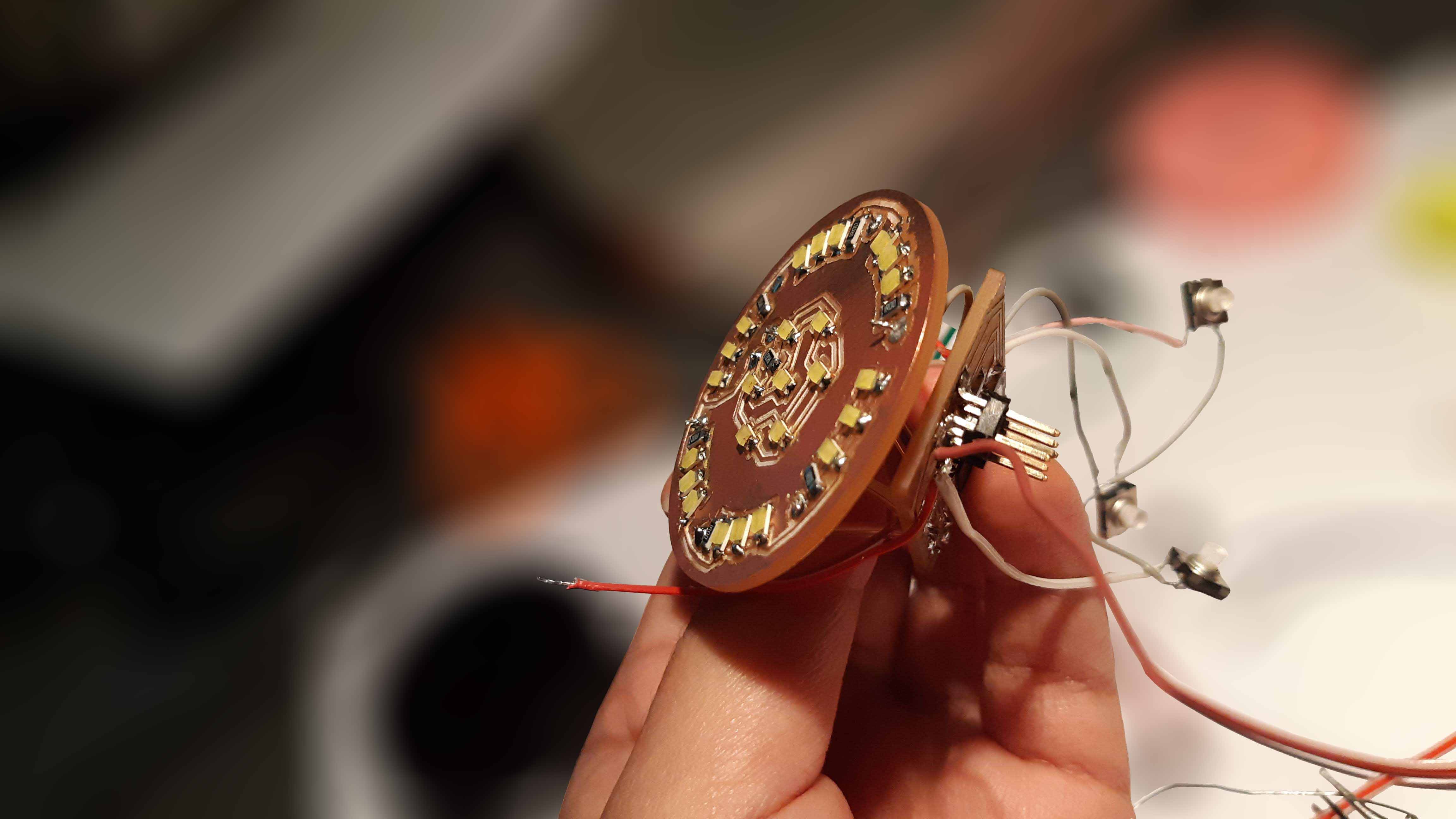
I realized I had made some mistakes connecting the pins, I was still able to make it work just switching some connections.
But as I wanted to have it right from the conception and also, having two separates boards, they occupy more space than what I would like, I decided I was going to make a new board.
NEW Mother board
Double sided pcb with eagle
To make this new double sided board I started modifying the schematic for the LED array board and added all the missing components.
While doing this I changed and fixed some connections following the modifications I had to do with the previous board.
Then I went to the board and arranged everything that was new, but to mill it on the other side. To do this you just need to right click on the component and select mirror, It will turn blue, this means it now belong to the bottom layer.
I also made the 3d for this board to be able to make it fit in the model design.
Milling process
For this part of the process I decided to use Flatcam once more. I have never made a double sided pcb before in my life, well that is not a surprise since the Fab Academy guided my first approach at all, to electronics.
This is why I looked for some more tutorials.
There are some out there, but this is the one that worked better for me.
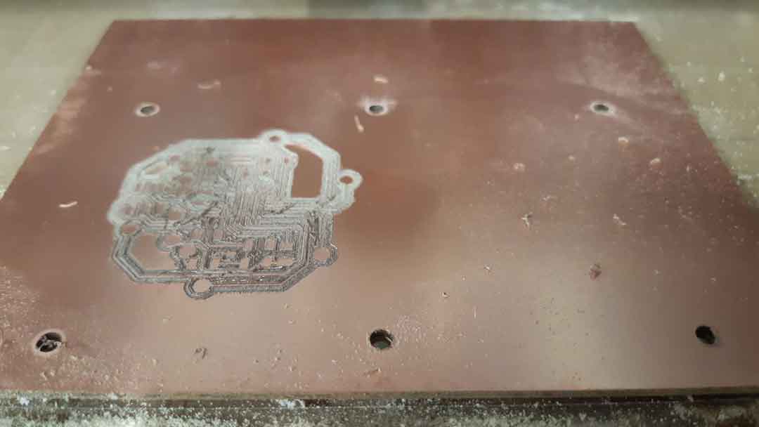
I started making the alignment drills, as you can see in both images below I did not use some pins as it was shown in the tutorial, instead I used some bolts just to make the alignment with the drills and secured the PCB with some double sided tape. Once it was completely secured I removed the bolts.
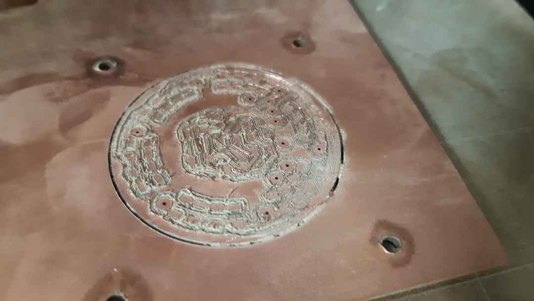
Here you can see the finish milled board.
I started soldering the microcontroller and all the other components that it needs to work. I wanted to try it and make sure it was a working board before soldering the LEDs.
As you can see in the image I had to fix it a little bit because one of the paths took of while I was soldering the 328p.
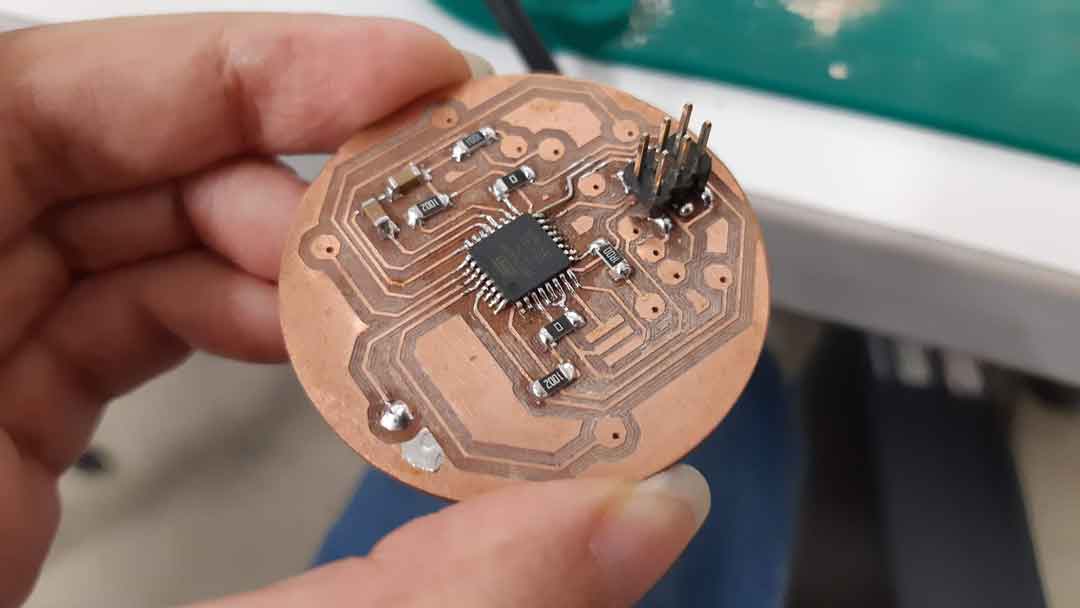
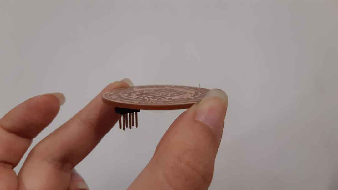
Just after checking it was working I started soldering the LEDs, but again I started with just a few and tested it.
Once I made sure of it I started soldering everything else and started testing again.
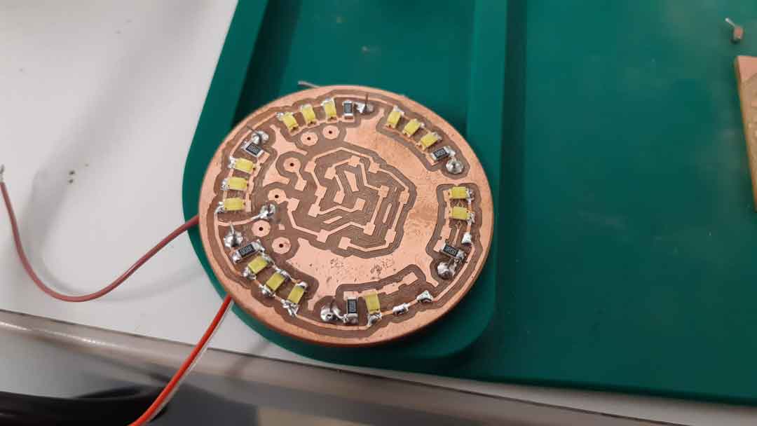
For this test I added the code I used for the Output week.
Programming new board
arduino
I used Arduino once more to program my board. It worked right away!
The only thing that didn't work from the star was the LEDs, so if you are making double sided pcb for the first time like me, make sure you connect the paths from one side to the other without forgetting any, in my case I didn't connect the ground. But after I did it was fixed.
I also burned the bootloader from arduino without any problems.
This is the button test after uploading the code.
And this is the motor test.
ENCLOSURE DESIGN AND MODELLING
Inventor 3D model
I don't have Fusion installed in my computer and also, I feel just a litle bit more comfortable with Autodesk Iventor, that is why I download the 3d board files from my Fusion 360 hub into .IPT files.
It is really easy, you just need to download the file, then select the file format, fusion will start processing the file, exporting it to finally send you an email with a download link.
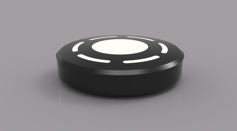
For the 3d model you can check all the steps made in the list on the left of the image. I build the top part form of extrusions and a chamfer to make it softer. The interesting part here is the circular array I made for the LEDs
For the bottom, I started again with an extrusion, but then I used the shell tool (which creates a shell with the wall thickness that is required). After that I used the emboss tool to make the spaces for the buttons.
When I had all the parts I made an assembly to check how everything would fit together
Having two boards inside the device I had no space left for the batteries or even the motor. You can check that 3d here.
With this new board, there is plenty space for the batteries and motor. That mission was accomplished!
FABRICATION
process
I used Cura as a slicer.
Layer height: 0.12mm
Shell thickness: 1.2mm
bottom/Top thickness: 0.8mm
Printing temperature: 210°C (this is what the default temperature for PLA but I usually change it to 205 or 200 directly to the machine)
Bed temperature: 60°C
Support type: Everywhere
I printed my model in PLA.