Fourteenth assignment
24 April 2019
Part I
Design, build and connect wired or wireless node(s)
Part II
Send a message between two projects
Week's assignment
This weeks individual assignment was to design, build and connect wired or wireless node(s) with network or bus addresses and the group assignment was to send a message between two projects.
I will be showing you the individual part below and the group assignment in the next page part II.
Board design
Serial bus
For this assignment I used Neil's serial bus example. I used the same components.
Here's what you will need for the bridge and 2 nodes:
Attiny 45 microcontroller (x3)
10k resistor (x3)
1uF capacitor (x3)
1k resistor (x3)
1 LED (x3)
ISP 2x3 pin header (x3)
Bus 2x2 pin header (x3)
FTDI 1x6 pin header (x1)
I redesigned the boards, this means I did the eagle files from scratch.
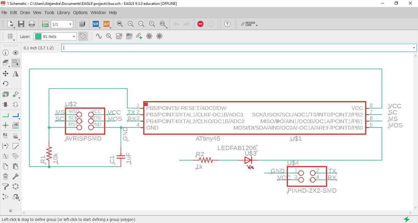
Node
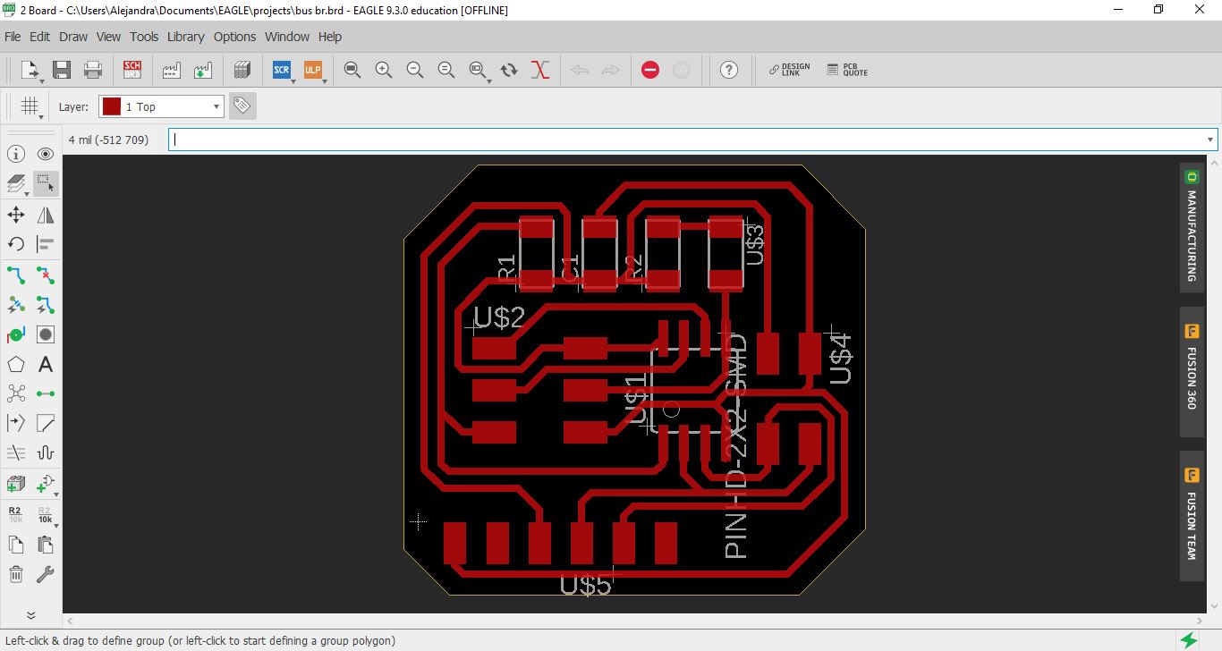
I decided to start with the node because the bridge was the same but without the ftdi pin header. I thought I could add that later. Here you can see the schematic for the node.
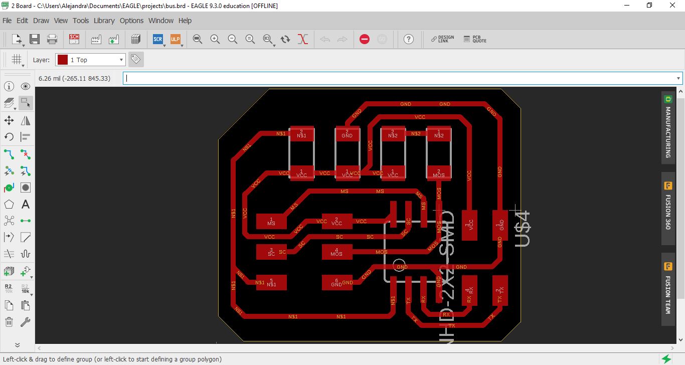
And here you can see the board.
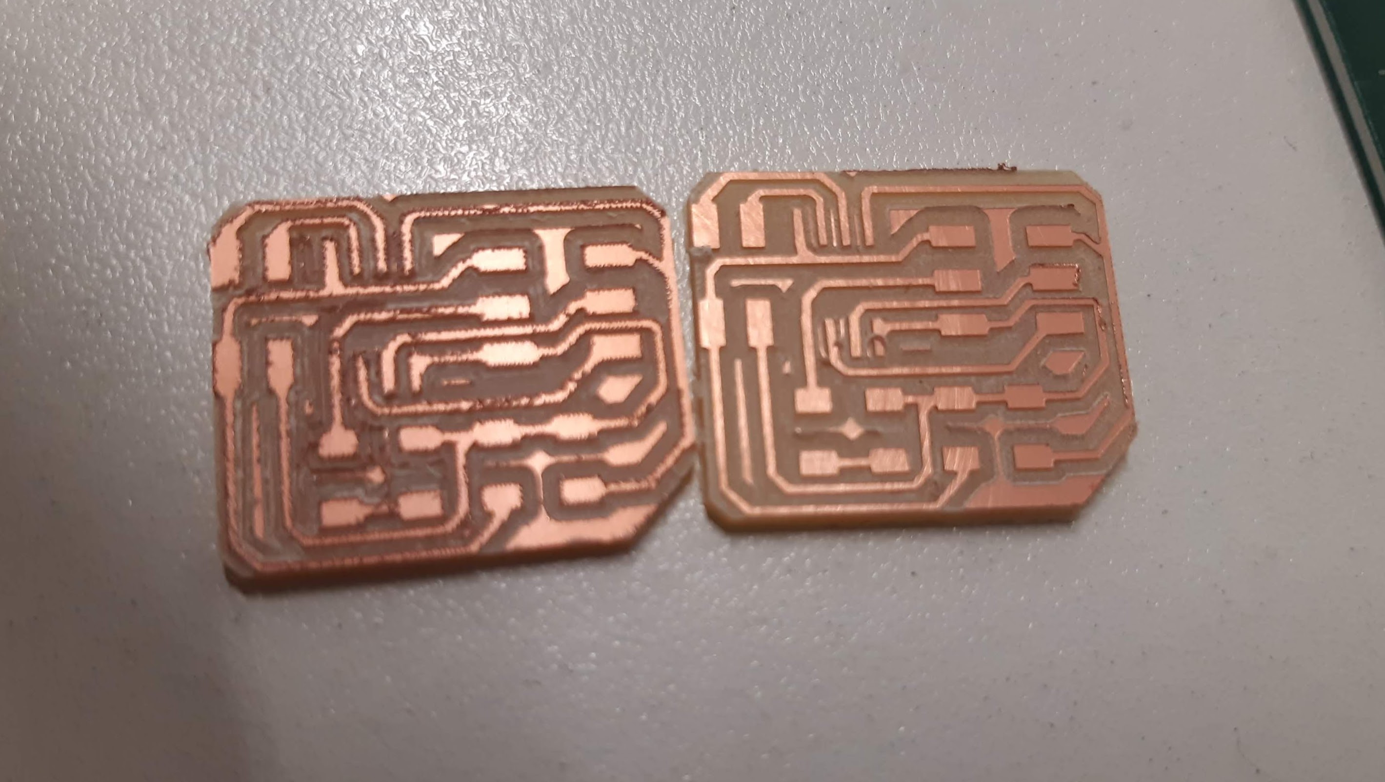
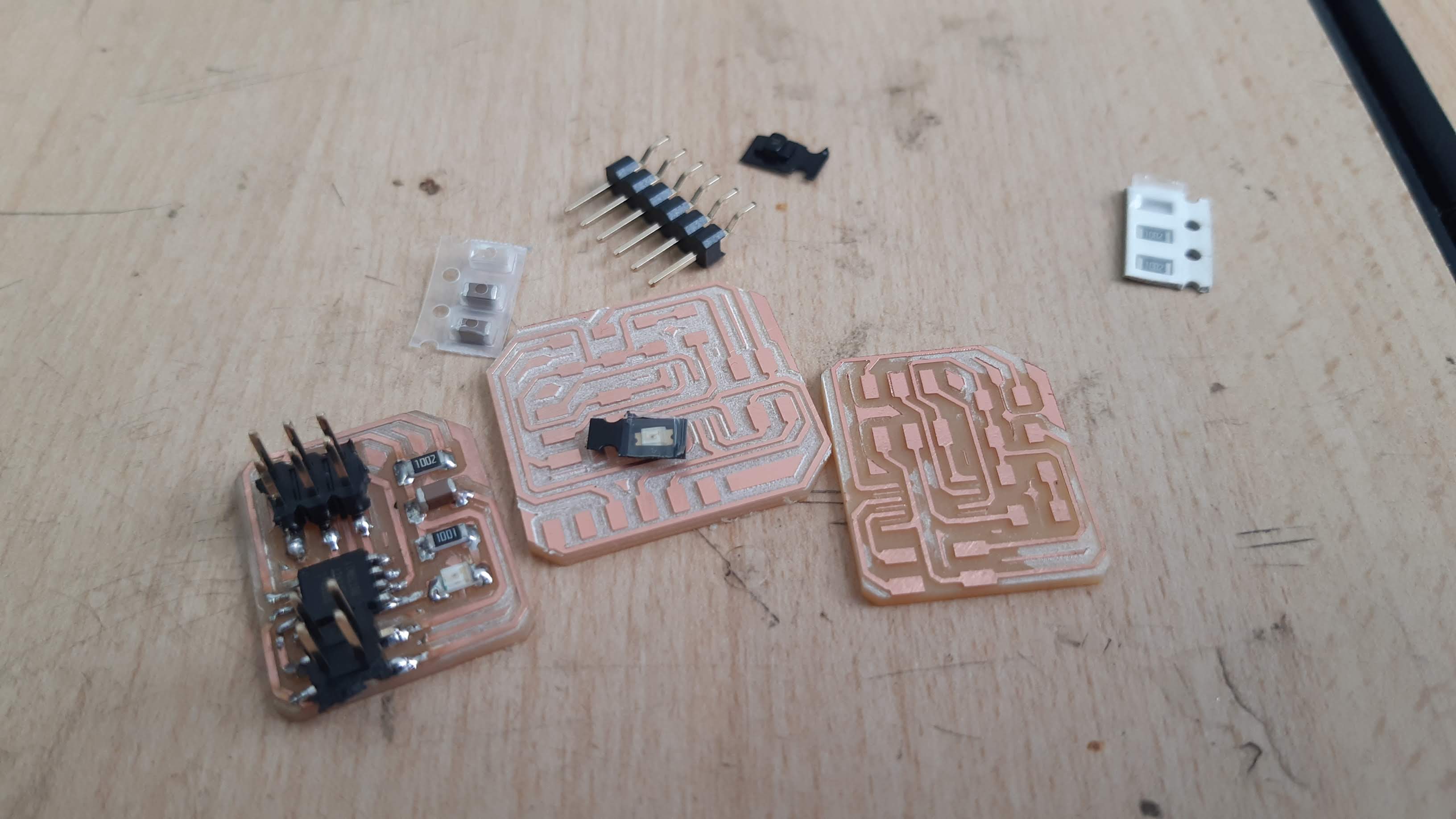
I proceeded to mill my design
I normally use a V shape endmill, as you can see in the next picture the left one has some burr in the surface, that happened because the endmill wasn't as sharp. I decided to changed it for a newer one.
This issue is completely fixable. A little bit of sanding works just fine.
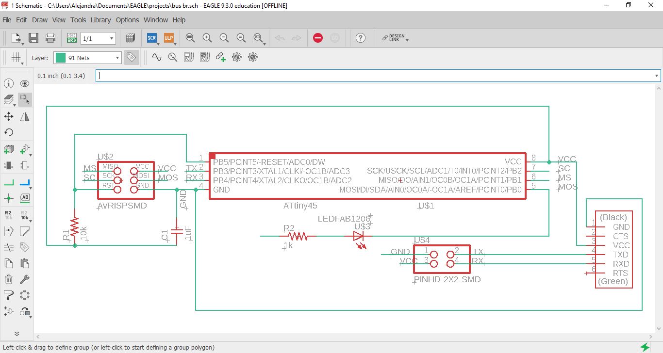
bridge
For the bridge I followed the same process and just added the FTDI pin header.
Controlling the routes width and running the DRC will help prevent issues when machining the board.
soldering components
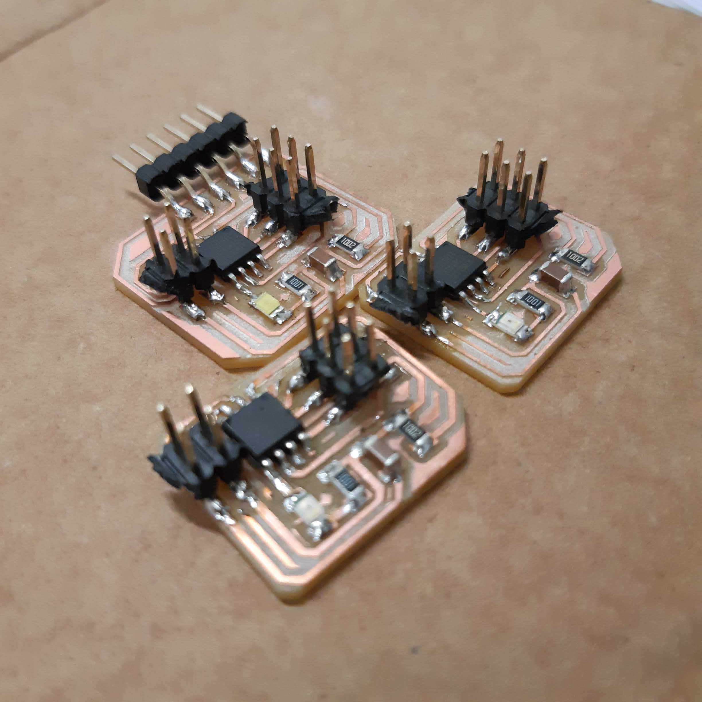
After the previous assignments and the experience gained this part turned out to be quite easy.
Here are the finished boards.
Board programming
Linux terminal
I normally use arduino for programming but this time I decided to go with the linux command line.
First thing we need to do is copy or download Neil's code, unless of course you want to do a different one.
Also the makefile.
the code
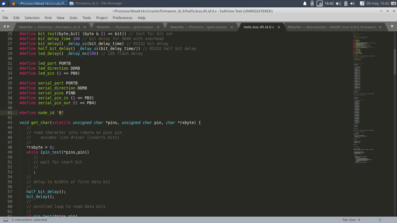
The code is the same for the bridge and the two nodes, the important thing is that we assign a different ID for each one. In line 41 there is #define node_id '0' that '0' should be replace with different values. I used 0, 1 and 2.
As you can see in the next image, I assigned a '0'.
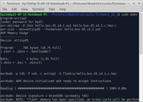
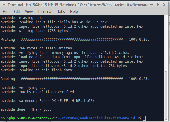
Once you have modified your code and have connected the board and the programmer, you can load the program by opening the terminal where the source code is located and run the command sudo program-avrisp2 (this command is the makefile). I am using the avrisp2 programmer but you should change that depending on what programmer you are using.
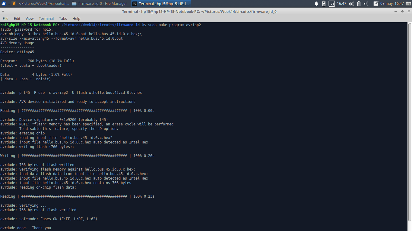
You should do this for each board. Connect it to the programmer, modify the node_id and load the program.
check operation
serial communication
To check the operation I connected the bridge board to the computer through the FTDI.
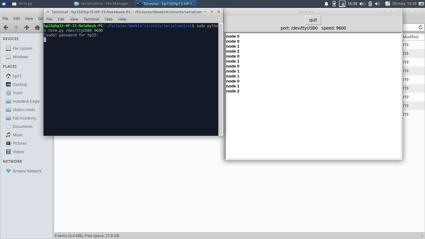
I opened the terminal where the Term.py. is located and execute it by running sudo python term.py /dev/ttyUSB0 9600.
With the serial monitor I started entering the 3 different values that were assigned to each board to see how it was working. For every interaction the three lights (one from each board) lit up at the same time. Then one of them lit up right away. This last blink depends on what number we enter in the monitor.
Here you can see how my boards work.
As you can see, just two of the LEDs were blinking but the bridge was working just fine transferring data. Because of this we can assume that the problem was just the LED, and it was. As i wanted to use different colors for each board, some of them had the GND marked differently and as the multimeter wasn't working properly I decided to give a shot but I ended up making a mistake when soldering. To fix it I just had to turned it around.
I connected it again and IT worked just perfectly.