Week 10: Networking and Communications
The main outcome of the week
Serial/UART communication
This week I’m going to work out the communication between the different microcontrollers. For the connection between boards/microcontrollers, I'll use physical wiring and UART protocol for communication. UART (Universal Asynchronous Receiver-Transmitter) uses two physical wires connected to Tx pin for transmitting messages and Rx pin to receiving messages. Also Baud rate, how many bits per second is sent (commonly 9600 bits/s), needs to be defined the same in both ends when establishing the connection as the protocol doesn't use clock as for example I2C but both ends need to know the rate of signals to understand each other.
For this assignment, I’m going to use the same boards that I used in input and output device assignments. The Time of Flight board (XIAO 0) sends data to two identical boards controlling servo motors: distance from 0 to 10cm controls XIAO 1 from 0 to 180 degrees and distance from 10 to 20cm controls XIAO 2 from 0 to 180 degrees. The hardware looks like this.

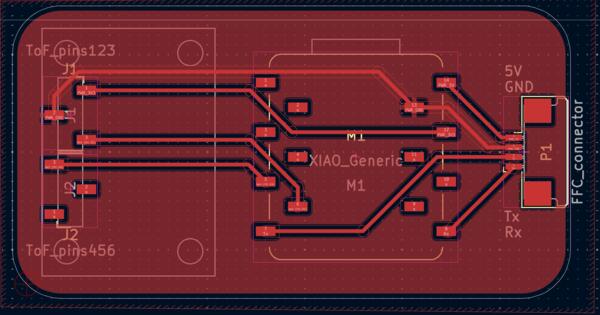
The PCB layout for the ToF-board, XIAO 0, (left in image above) looks like below as in Week 8: Input devices documentation. Tof sensor gets 3.3V from XIAO board and is connected to its I2C pins. On the right side, as written on the board, there's 5V, GND, Tx and Rx pins connected to the connector that goes to the servo-board XIAO 1.
The PCB layout for the XIAO 1 and XIAO 2 is shown below and it is documented in Week 9: Output devices. The 5V from the XIAO 0 is useless as the 5V for servo is taken from the XIAO 1 board and GND goes to fill zone. What was Tx in XIAO 0 goes to Rx in XIAO 1 and Rx to Tx and are also connected to the connector going to XIAO 2 (this way of connecting the pins turned out wrong). On the right side there's the level shifter that works between XIAO board and servo connector on top right. The connector below goes to XIAO 2 that is similar to this board (which doesn't have any further connections for the connector on the right).

As the hardware is already there, I begin with programming. The first thing is to set up a serial connection between the sensor board and the XIAO 1. To figure out how to do that I googled “circuitpython how to establish UART connection” and ended up in CircuitPython Essentials by Adafruit. From there I found out about busio library and looked for its documentation.
I began with the example code for reading the messages and pasted it to XIAO 1. I commented the servo code from previous task away for now. In addition, Claude (prompted by Kris) gave an example code for sending messages with write-function and that I pasted to the XIAO 0 (image below). For both, I added code for blinking the LED to make visible the USB connection when established.

Then I tested the program by powering up the ToF board with my phone charger and the servo board from the computer. The messages were sent but were somewhat unstable and cryptic.

Kris came to check how I was doing and mentioned about the baud rate and when checking on that I realized that I hadn’t defined timeout for XIAO 1. I checked the busio documentation and timeout is 1 by default. So I set that to 0.1 to match XIAO 0 but it didn’t solve the messaging (or only slightly perhaps?).
Next I started checking on the code as they were copy-pasted from different sources, and thought that the conversion from bytes to strings might cause the issue. I didn’t really understand the write-function and the message formatting ( uart.write(b”Hello/r/n”) ) to begin with (explained a bit later here). I added print(data) in the XIAO 1 code to view the message as it comes.

I understand this so that when the message comes as it is sent, as b"Hello\r\n", the receiving end is able to parse it correctly, but when the data is printed as longer line of symbols, the output message becomes cryptic. So the problem might not be in parsing data into string.
As I came back to this after the weekend and connected the XIAOs and got the connection established, the messaging suddenly work as supposed to so I don't know what was issue about.

Then I moved on to try to make the servo run based on the message. I couldn't get the code to understand the message with if statement 'if data_string == "Hello":'. With print(type(data_string)) I get info that it's a class that is a string. I try to understand the write-function and the message-formatting inside it. In busio-library it's explained as below.

I asked Gemini to explain me the write-function of busio library, because I didn't understand the formatting of the given code: what are "b", "/r" and "/n"? So basically b translates the string into a byte format and /r moves cursor back to left and /n begins a new line in the text (this one I actually knew).


So what is written inside the parenthesis is the message being sent, but it needs to be converted to byte-type, and there was nothing extra regarding the messaging protocol or such: they were only formatting the message.
Instead of figuring out the class/string type (which would've probably been solved by 'if data_string[0] == "Hello":'), I thought I could anyway update the XIAO 1 code to send 0 or 1 instead of "Hello". However, Gemini suggested to use string type as it's easier to debug apparently. Well, I went on with int-types anyway and asked how to send and receive it. To make number 1 into bytes I used uart.write(bytes([1])) and for data = uart.read(1) and number = data[0].


After a while of debugging (which was solved by having the above mentioned lines in place) I was able to make the servo run 180 degrees based on the message (1 or 0) and turning back every second.
XIAO 0 (ToF/sending) code:

XIAO 1 (servo/receiving) code:

Then I moved on to include ToF to message sending. I went back to the Adafruit's sample code and copy-pasted that (excluding all the unnecessary print commands as shown below).

Then I began integrating it to the previous code used with messaging. I wanted to make it so that 18cm distance is 0 degrees and the servo moves 10 degrees on every cm that my hand moves closer. Here I converted the distance to string when sending it and converted back to int when receiving.
XIAO 0:

XIAO 1:

Now the XIAO 0 sends the distance in centimeters, which converts in the XIAO 1 code to int with the same code. Multiplying that by 10 and setting it as angle makes the servo move based on the proximity of my hand.
There was a "ValueError: Angle out of range" when my hand was too far so I added some limits to the angle given to the servo: it needs to be larger than 0 and smaller than 180

The servo is quite jumpy because it receives the angle in tenths, so I went back to send floating numbers as strings. I added "/n" to it so that readline method can be used in opening the messages.
XIAO 0

First this code gave TypeError: string argument without an encoding, but when I added "utf-8" along with the write-function, as given in an example by Gemini, the error disappeared. Then I used, as in Gemini's example, float(data.decode().strip()) to convert the byte type to floating number.
XIAO 0

XIAO 1

Now it moves a bit smoother as the angle is given in one degree accuracy.
Being ready to connect the second servo board and send messages over three boards, I can't do it as easily, because I lost all my electronics due to a stupid mistake (left the box on top of my car when I drove away). Now I'm in a decision should I start this experiment from the start to be able to document the last couple of hours of work, or continue with the next thing, i.e, my final project which has also networking (bluetooth) element to it.
I decided to go through how the communication would have been implemented if I still had my components at hand, and then document later how I implement a bluetooth connection with my final project.
Basically adding third board to the communication chain, does not bring much complexity: I only need to add an address, eg. 1 and 2, to the sent message, add those address-ids and if-statement to both XIAO1 and XIAO2 so that they react only if the address corresponds to their address-id. This is demonstrated in the image from Neil's material.

As is seen in the XIAO1 and XIAO2 PCB layout, the serial bus goes to both the microcontroller and the next connector. This means both XIAOs are receiving the same message.
It turns out this is a wrong way to do this: the first microcontroller should forward the message to the next one, instead of only receiving it. The image above was somewhat misleading for me as it implies one bus that goes untouched and is branched to every "address". As I'd comprehend it, the vertical arrows are not actual buses and the states should be located on top of the thick bus-lines, implicating the forwarding. Below is the documentation of this learning process.
A few weeks later...
Now a few weeks later I'm back on this and made all the boards again in one day (of which most of the time went to desoldering an used XIAO board that I found at the lab). The next day I installed CircuitPython on all of the XIAOs and as I began adding the code, I realized how lacking my documentation had been here on that front. Anyway, it was good learning over repetition as I coded the programs again using the same resources and some screenshots I had provided before. I was able to make each board work individually quite soon.
I approached the communication by adding 1 and 2 in the beginning of the message depicting which XIAO the message should reach.

I began working with XIAO 0/ToF-board and XIAO 1/first servo board. For XIAO 1 code I added else statement to forward the message if the first symbol in the message is not 1.

When testing, the servo in XIAO 1 didn't run. With print-commands I debugged that the message never got over the first, if uart.in_waiting > 0: -statement. I rechecked how I had done it before and changed this:

to this:

Now it got over the first if-statement but didn't work. As I was debugging with print() and then checking the code, I realized that there was .strip()-method missing in the second if-statement.

Here's the print output that made me realize the bug as well as the necessary change made.

Also on the next line there was an error with the decode: [1:] was before strip() and below an instant recorrection.


The messages still didn't come through, and after a while I found out the mistake in XIAO 0: the if-statement needed intgers to make the comparison.

Now I had the servo running with the following codes:


I changed code.py filenames to main.py as it appeared that code.py didn't run automatically when connected to power but main.py did.

Except when I tried the code with XIAO 2 it didn't work, but then I found a typo: an extra 5 had sneaked in.

But XIAO 2 still didn't receive anything. I became to think that the problem is in the hardware. I asked Gemini what I don't get: I gave the context what I'm trying to do and gave a screenshot the PCB layout. It became clear that the UART messaging doesn't work like that. I prompted Gemini to explain this thoroughly. However it was confusing the pin names quite badly (XIAO and KiCad name the pins differently and in addition I had named Tx and Rx the opposite way in the PCB Layout image I provided), so I wasn't exactly sure if it did hallucinate something else as well. but (I believed) I got the main idea: the XIAO 1 needs to forward the message instead of it being routed directly to both XIAO 1 and XIAO 2. I ended up scratching the Tx and Rx routes to XIAO 2 and replace it with wire from XIAO 1's Tx to XIAO 2s Rx.

But the messaging still didn't work as supposed to.
I discussed a bit later with Kris about it and I understand that the Rx and Tx pins are for the network between the first two boards and the XIAO 1 should use another pin to forward the message. So I clip the wire and move it to the next pin.


I also needed to change the pin name in XIAO 1 uart definition.

The messages still didn't reach XIAO 2 (correctly) as the following print statements showed me.

Checking code on XIAO 1, there was a clear error in the else-statement: the XIAO would need to read the distance before the if-statement for this to work.


But then I realize that it doesn't need to know the exact distance as it can just send the same data-variable it read.

And now it worked.
Here are the programs explained for each board.
# Code for XIAO 0 / ToF board

import board   # Accessing the XIAO board's pins
import busio   # Module for controlling serial bus and I2C
import adafruit_vl53l4cd   # Time of Flight -library

uart = busio.UART(board.TX, board.RX, baudrate=9600, timeout=0.1)   # Initialize UART, pins, and baud rate,

i2c = board.I2C()   # Initialize I2C bus, SDA and SCL pins, and set as variable i2c
vl53 = adafruit_vl53l4cd.VL53L4CD(i2c)   # Initialize sensor and connect it to the I2C bus

vl53.start_ranging()    # Start measuring

while True:   # Establish loop that goes through the execution
    while not vl53.data_ready:   # If no data -> loop ends (and begins again), if data -> continue
        pass
    vl53.clear_interrupt()    # Clears data
    distance =  vl53.distance   # Define variable based on measured distance
    print(distance)
    if int(distance) < 10:   # Under 10cm distance is sent to XIAO 2
        uart.write(bytes("2" + str(distance) + "\n", "utf-8"))   # Sends a string to uart bus
    elif int(distance) < 20:    # Under 20cm distance is sent to XIAO 1
        uart.write(bytes("1" + str(distance) + "\n", "utf-8"))
# Code for XIAO 1 / Servo board

import time   # Used for delays
import board   # Accessing the XIAO board's pins
import pwmio   # Pulse Width Modulation
import servo   #
import busio   # Module for controlling serial bus

# Initialize UART, pins, and baud rate,
uart = busio.UART(board.D5, board.RX, baudrate=9600, timeout=0.1)

# Generate 50 Hz PWM signal on pin D10
pwm = pwmio.PWMOut(board.D10, duty_cycle=2 ** 15, frequency=50)

# Connect servo driver to PWM with pulse-width with pulse limits,
my_servo = servo.Servo(pwm, min_pulse=500, max_pulse=2400, actuation_range=180)

while True:   # Establish loop that goes through the execution
    data = uart.readline()   # Check if UART is sending data
    if data is not None:   # Check if data was received
        if data.decode().strip()[0] == "1":   # Decode and strip message and check if first letter is 1
            distance = float(data.decode().strip()[1:])   # Create float variable from the rest of the message
            angle = (distance - 10.0) * 18   # Define angle based on distance
            if angle < 180 and angle > 1:   # This to avoid errors in angle values
                my_servo.angle = angle   # servo-module calculates the angle for the servo
            time.sleep(0.05)   # 0.05s delay
        else:
            uart.write(data)   # Send the message forward
# Code for XIAO 2

import time
import board
import pwmio
import servo
import busio

# Initialize UART, pins, and baud rate,
uart = busio.UART(board.TX, board.RX, baudrate=9600, timeout=0.1)

# Generate 50 Hz PWM signal on pin D10
pwm = pwmio.PWMOut(board.D10, duty_cycle=2 ** 15, frequency=50)

# Connect servo driver to PWM with pulse-width with pulse limits,
my_servo = servo.Servo(pwm, min_pulse=500, max_pulse=2400, actuation_range=180)

while True:   # Execution loop
    data = uart.readline()   # Check if UART sending data
    if data is not None:   #
        if data.decode().strip()[0] == "2":   # Decode and strip message and check if first letter is 2
            distance =  float(data.decode()[1:].strip())   # Create float variable from the rest of the message
            angle = distance * 18   # Define angle based on distance
            if angle < 180 and angle > 1:   # This to avoid errors in angle values
                my_servo.angle = angle   # servo-module calculates the angle for the servo
            time.sleep(0.05)   # 0.05s delay