Mechanical Design & Mashine Design
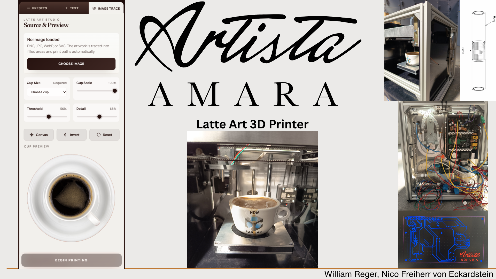
Latte Art Machine Project Documentation - “Artista Amara”
As part of FabAcademy Machine Building Week we developed Artista Amara, a machine intended to automate parts of the latte art process through a combination of motion control, milk foaming, sensor feedback, relay-based actuation, and a browser-based user interface. Over the course of roughly two weeks, we invested around 330 hours into the project.
Although we each had areas in which we naturally took the lead, this was very much a shared build. Nico often had a stronger supervisory role during hands-on workshop and assembly tasks, while William took more responsibility for digital planning, electronics integration, firmware work, and the software side of the system. Still, we were both active in both domains throughout the project. The machine is therefore the result of continuous collaboration rather than cleanly separated roles.
Concept
Task group: Define the machine
Compared machine ideas
The project began with an open ideation phase. We explored several possible machine concepts, including a latte art printer and a Zen marble sand printer. This comparison helped us evaluate which idea would create a realistic, but still challenging, machine-building project. The latte art printer stood out because it combined several different technical areas in one system: mechanical motion, liquid handling, heating, milk foaming, user interaction, sensor feedback, and software control. In addition, the concept felt very innovative to us and immediately caught both of our interest. The idea of creating perfect latte art with a machine, without needing any special barista skills, was one of the main motivations for choosing this project. It gave us a clear goal and pushed us to take on a complex machine-building challenge. Because of this motivation, we were willing to invest a lot of our free time into developing the machine. We already started the ideation process in Week 1, so that we had enough preparation time before the actual machine-building week. This early start helped us compare different concepts, discuss possible technical challenges, and decide which direction would be the most interesting and feasible for us.
Nico: 50%
William: 50%
Sketched machine function
After narrowing down the concept, we defined the rough machine functions and overall layout.
The goal was to build a system capable of preparing and dispensing milk into coffee to create cappuccinos and draw latte art on the coffee surface in a controlled and repeatable manner.
From the outset, it was clear that this could not be approached as a purely mechanical project.
Motion systems, milk foam generation, electronics, and software all needed to be developed in parallel, as every decision affected the rest of the system.
To ensure the system would work and no critical aspects were overlooked, we created sketches and plans early on. Although we started with these initial sketches, we revisited and refined them multiple times throughout the project. Tests and assembly revealed several issues, which required us to update our plans and drawings to develop a more detailed and realistic understanding of how the machine would ultimately be built.
Nico: 50%
William: 50%
Project Management
Task group: Manage the build
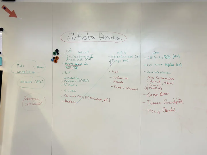
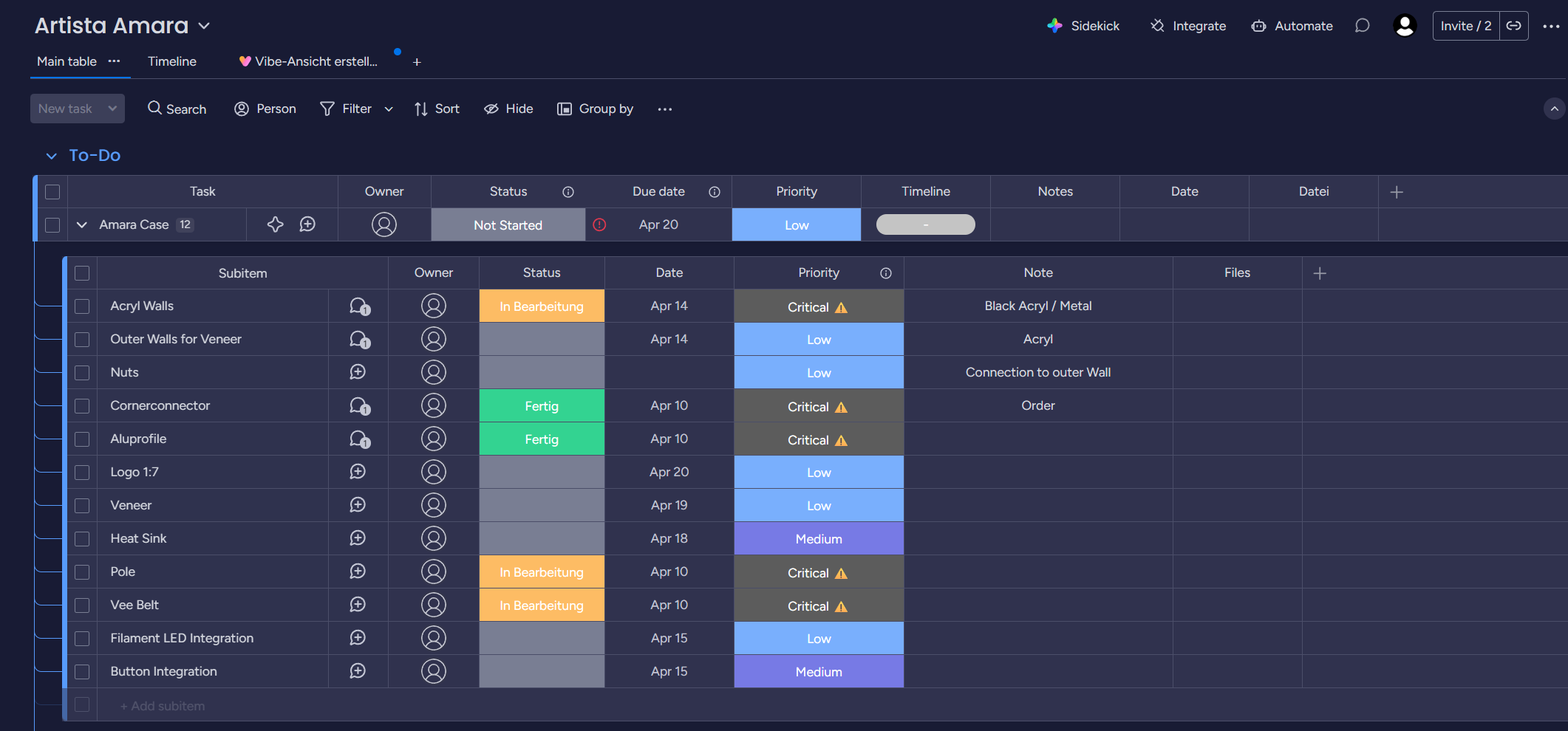
Structured task groups
We organized the machine build into task groups and assignments, which allowed each area of the project to be planned and discussed more effectively. This structure included concept development, parts salvage, planning, plumbing, testing, frame construction, motion systems, case fabrication, print head development, logic circuit design, electronics, and overall integration. It helped us identify which parts of the machine were stable and which areas still required attention. To manage the project more efficiently, we used Monday to document tasks and maintain a timeline for the entire development process. This provided a shared space to track what had been completed, what still needed to be built, and how the different work packages related to one another. It also kept the machine work visible as an ongoing project rather than a loose collection of workshop tasks. While this structure supported better time management, the workload remained challenging. Some tasks did not go as planned, which inevitably contributed to delays, but the overall organization helped us stay on top of the project’s complexity.
Nico: 30%
William: 70%
Maintained build backlog
We maintained a build backlog throughout the project to keep track of unfinished work and newly discovered problems. The backlog changed repeatedly because machine failures, misleading documentation, fabrication issues, unavailable or non-working machines, and constraints discovered during assembly kept shifting the plan. In many cases, we first had to maintain or troubleshoot machines before we could even use them. Some machines did not work at all, which created major difficulties and delayed several steps of the project. Even with project management, the schedule slipped several times because new information often only appeared once parts were installed, tested, or failed under real conditions.
Nico: 70%
William: 30%
Salvage
Task group: Collect and strip donor hardware
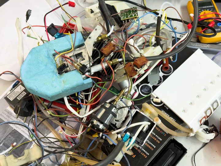
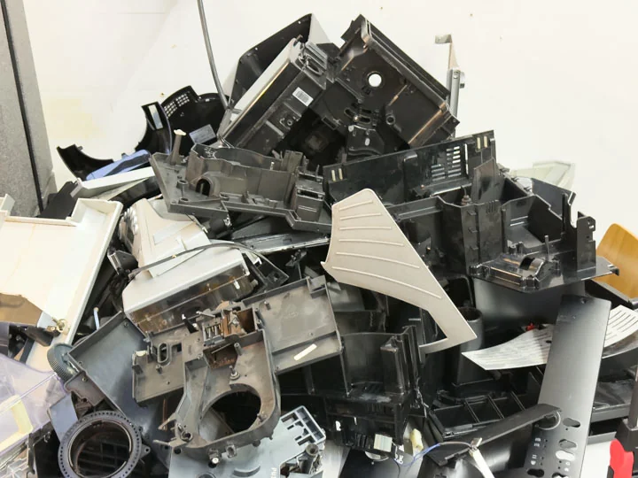
Collected coffee machines
We collected used coffee machines through eBay Kleinanzeigen and treated them as donor hardware for fluid and heating components. These machines provided parts that were directly relevant for pumping, heating, and foaming. Working with used coffee machine parts also helped us understand what could realistically be reused and what would need custom adapters or new fittings.
Nico: 50%
William: 50%
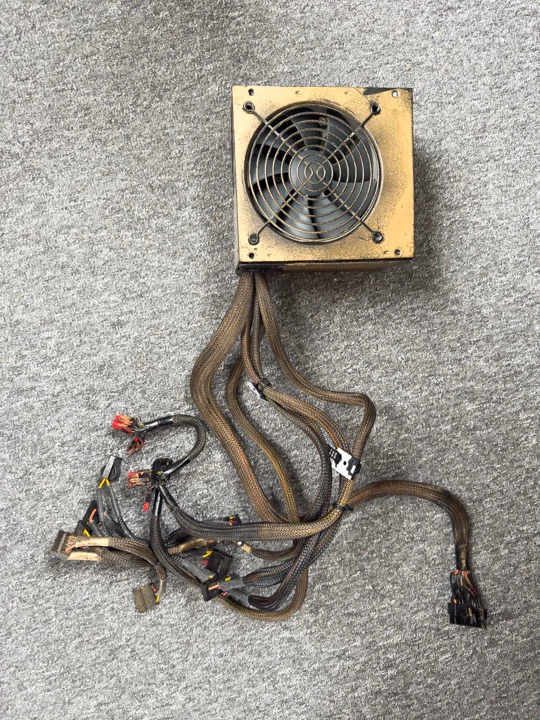
Collected ATX PSU, ANET V1-5, Ultimaker Mini, Prusa MK3
We also sourced the PSU, stepper driver board, and axis components from used parts. A 600 W ATX power supply was salvaged from an old computer and repurposed as the machine’s main power infrastructure. This PSU provided all required voltages—3.3 V, 5 V, and 12 V—through a single unit, eliminating the need for multiple power supplies. The old Ultimaker Mini served as a primary donor system for the machine. Structural and motion-related components were reused wherever possible, and the side panels were later adapted to fit the new body. The Ultimaker parts were not simply transplanted; they were cut, modified, sanded, and integrated into a new geometry specifically designed for the latte art printer concept. During the process, we realized that the Ultimaker’s stepper motors had to be replaced, as they were designed for 24 V operation, while our system could only supply 12 V. We therefore sourced spare parts from upgraded Prusa MK3 printers in our lab. The ANET V1‑5 board was collected as a potential low-level controller for the motion system and relay-driven outputs during the drawing process. Over the course of the project, we explored how to repurpose it beyond its original 3D printer context. This became a key technical challenge, as the board needed to be understood, modified, flashed, and integrated with the Raspberry Pi architecture.
Nico: 50%
William: 50%
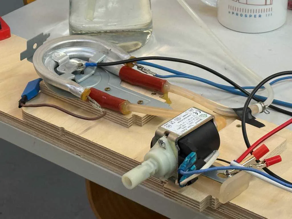
Extracted pump & heating element
We extracted a pump from the donor hardware so it could be reused in the milk and fluid-handling path. The pump was one of the most important components because the machine depended on controlled movement of liquid or foamable medium. After extraction, the pump was tested and later considered as part of the relay-driven machine subsystems.
We extracted a heating element from the donor coffee machine hardware. This component was important for the milk preparation and foaming side of the machine. It was tested separately before being integrated into the broader system, because heating elements and mains-level components had to be treated carefully and planned into the electrical structure.
Nico: 50%
William: 50%
Planning
Task group: Plan mechanics and sourcing
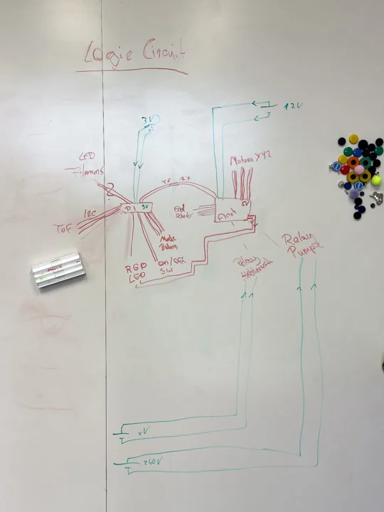
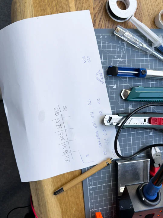
Worked out schematic
In parallel with dismantling donor machines, we worked out the basic electrical structure of Artista Amara. We mapped the relationships between the Raspberry Pi, the ANET board, the relays, the sensor system, the higher-voltage components, and small electronic parts as buttons or LED filament. This planning step was necessary to turn the concept into a buildable machine architecture instead of only a collection of parts.
Nico: 50%
William: 50%
Planned frother
The frothing setup was planned as part of the machine’s process chain, not as a separate accessory. It had to connect to the pump, heating-related components, air input, valve behavior, and nozzle path. The foaming experiments later showed that this part of the machine depended strongly on the relationship between air input and milk flow, so the frother position and integration were treated as part of the full system logic. The frothing setup was one of the most difficult parts of the whole machine. Our original idea was to use components that were already available and upgrade them only with a few small additional purchases to create milk foam. In hindsight, it would probably have been smarter to invest around 150 € in a finished frothing unit, because building our own setup took a lot of time. We had to build the hardware, test it, modify it, rebuild it, and test it again many times. We tried many different systems and setups before we reached our final concept. This made the frothing part very time-consuming, but it also helped us understand how sensitive the process is and how strongly the foam quality depends on the correct interaction between milk flow, air input, pressure, and the mechanical integration into the machine.
Nico: 70%
William: 30%
Researched stable foam for visual media
We also investigated how photographers and video producers create especially stable foam for recordings. This was relevant because our system did not just require any foam, but a reproducible and visually suitable foam structure. Through this research, we better understood that foam stability, bubble size, and homogeneity strongly depend on how air and liquid are introduced and controlled. This also led us to look more closely at different liquid and foam alternatives. For example, we considered barista oat milk, because it is often optimized for better foam behavior and can contain added oil or fat components to improve texture and stability. We also discussed shaving foam as an emergency visual substitute, but only as a backup option for testing or presentation purposes, not as a real food-safe solution. Another idea was to mix cream into the milk to increase the fat content and potentially improve the foam stability. We also considered pre-foaming the milk slightly before guiding it through our own system. This could have helped the machine by starting with a liquid that already had some air incorporated, instead of requiring the complete foaming process to happen only inside our setup.
Nico: 80%
William: 20%
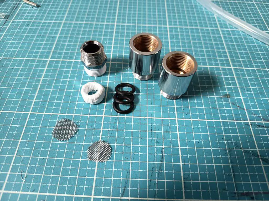
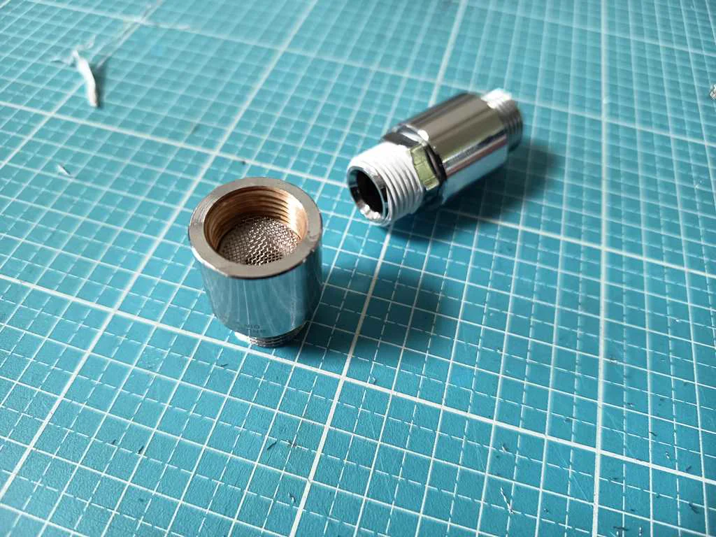
Evaluated mesh and screen structures
We explored suitable mesh and screen sizes for milk foaming. This was included directly in the frothing part of the machine, because the screen structure was one of the main elements that influenced bubble formation, air distribution, and the resulting foam texture. For this purpose, we designed an adapter that allowed us to place several screens behind each other. This made it possible to test different combinations and observe how multiple screen layers affected the foam. The adapter was significantly thicker than the rest of our hose system. While our hoses had an inner diameter of around 6 mm and some adapters went up to about 11 mm, the screen adapter was slightly larger than 3/4”. This size difference was important because it changed the flow behavior inside the frothing section. The wider adapter created more space for the screens and for the milk-air mixture to pass through them, but it also had to be integrated carefully into the smaller hose system. These considerations helped us interpret the later experiments with screens, kitchen sieves, and other improvised foaming elements more systematically.
Nico: 90%
William: 10%
Considered the influence of pump, heat, and screens
We also examined how the pump, heating element, and screens together affect foam quality. Instead of looking at these parts separately, we treated the foaming process as a system in which flow behavior, temperature, resistance, and fluid dynamics interact directly. This was important because the milk-air mixture does not simply move through the system in a linear way. The pump creates pressure and flow, the heating element changes the temperature and viscosity of the liquid, and the screens create resistance, turbulence, and finer distribution of air bubbles. All of these effects influence each other. For example, too much resistance can reduce the flow rate or create unstable pressure conditions, while too little resistance may not break the air into small enough bubbles. Because of this, we had to consider the fluid dynamics of the whole setup. The hose diameter, adapter transitions, screen position, air input, and pump behavior all affected how the milk and air moved through the system. This helped us understand why small changes in the hardware could have a large effect on the final foam quality. By treating the foaming setup as one connected process instead of separate components, we built a stronger conceptual basis for later practical foaming tests with real hardware.
Nico: 60%
William: 40%
Evaluated pump selection and behavior
We examined different aspects of pump selection and the behavior of already available pumps. The main question was whether an extracted or reused pump would be suitable for the planned fluid system and how well it could be integrated into the machine. The pump did not only need to move liquid, but had to work in combination with air input, valve control, and foam generation.
Nico: 90%
William: 10%
Considered behavior at lower voltage
An important question was whether our pump would simply run slower at reduced voltage or if its behavior would change in a more fundamental way. This was critical because it directly influenced possible control strategies and the technical suitability of the pump for our system. Evaluating this allowed us to determine whether voltage reduction could serve as a practical method of regulation.
We also assessed whether, and to what extent, the selected pump could actually be throttled or regulated. This was central to the project, as foam quality depends heavily on a controlled relationship between liquid flow and air input. Our investigation revealed that the pump could not be adjusted in this way, so we needed to control foam quality through other parameters, such as the amount and consistency of air supply.
The same issue applied to the valves salvaged from other machines, which were designed for 24 V operation—an operating voltage unavailable in our machine. Through testing, we confirmed that the valves functioned reliably under our system conditions, at least for the purposes of our experiments.
Nico: 50%
William: 50%
Considered tube pinching as a valve principle
We investigated whether pinching a tube could serve as a simple valve principle for the machine. This idea was especially interesting because it would avoid direct contact between the valve mechanism and the fluid. At the same time, it offered a potentially low-cost and quickly implementable solution using relatively simple mechanical means. Based on these considerations, we also developed the idea of building our own pinch valve. The focus was both on mechanical feasibility and on the fluidic consequences of such a solution. The goal was to find a simple, integrable, and sufficiently reliable method for controlling milk or air lines within the machine. We also explored whether existing components could be repurposed for this kind of flow control. This fit well with the overall project approach of reusing as many available or recycled parts as possible. These investigations helped us assess possible solutions not only in theory but also under real workshop and lab conditions. Unfortunately, due to time limitations and missing equipment in the lab, we were not able to fully complete this part of the project. Small servos were too weak to reliably pinch the tube, while integrating a larger motor would have been too time-consuming and mechanically more complex. We also tested an available actuator, which was originally intended as an electric latch for a small door or a similar mechanism, but this part was also not strong enough for our use case. We also considered using a peristaltic pump, but this was not suitable because of the fluid dynamic behavior of the foam. Since a peristaltic pump works by repeatedly squeezing the tube, it would most likely damage the foam structure and cause foam loss. For this reason, it was not a good solution for our valve function, even though the general principle of tube pinching was still interesting for separating the mechanism from the fluid.
Nico: 100%
William: 0%
Researched solenoid valves and pinch valves
We also researched suitable solenoid valves for water and compared normally open and normally closed concepts. In parallel, we looked into suitable pinch valves for the intended tube size of 6 mm inner diameter and 8 mm outer diameter. This research was important for making a more informed decision between purchased parts, improvised solutions, and self-built mechanisms.
Nico: 70%
William: 30%
Considered fluid dynamic effects
Besides the component search itself, fluid mechanics also played an important role. We considered how different valve principles might affect flow rate, switching behavior, dead volume, and overall system resistance. These reflections were necessary because the valve choice directly influences the performance of the full foaming and dispensing system.
Nico: 80%
William: 20%
Prepared AliExpress order
We prepared an initial AliExpress order for general integration parts such as buttons, tubing, and components needed to connect the reused hardware to the new machine. This sourcing step helped close the gap between what could be salvaged and what had to be bought. The ordered parts supported the mechanical, plumbing, and interface layers of the build. However a few of the parts were not needed at all as we saw later on. It was mainly for the initial testing and prototyping. Tubes for example were not food safe - some connectors were not made from stainless steel etc. But it was the perfect - however not fully sustainable way - to get a better view of the complete machine working as one. And the leftover parts will definitely be used in future projects anyway.
Nico: 30%
William: 70%
Prepared Reichelt order
After some initial tests as well as the Aliexpress order helped us to get a clear picture of what exactly we had to archive. So we prepared a more specific Reichelt order for core electronics and system integration components. Important ordered elements included relays, a logic level converter, the Raspberry Pi Zero 2W, JST connectors, wiring, a tank, hoses, and hose clamps. These parts were necessary to create stable interfaces between the motion controller, the Raspberry Pi, and the higher-voltage or fluid-based hardware.
Nico: 10%
William: 90%
Researched veneer and finish
We researched veneer and finishing options because the machine was intended to be a coherent prototype, not just a technical frame. The old Ultimaker side panels were cut down and sanded to reveal their aluminum finish, while the outer acrylic panels were planned to be covered with veneer. Decorative elements, such as the logo and LED filament accents, were also designed to give Artista Amara a recognizable visual identity. However, due to time constraints, this step could not be implemented during the two-week machine building period.
Nico: 50%
William: 50%
Precise planning of the machine after testing
We further developed the precise concept of the latte art 3D printer based on the functional behavior we had tested before. We tried to combine the individual subsystems in a way that turned isolated ideas into a coherent technical architecture. The goal was not only to define how the machine should work, but also how it could realistically be built. A major part of the planning process was to integrate available or recycled components from the lab inventory into the system wherever possible. For that reason, we evaluated which parts could be reused and what technical limitations had to be considered. At the same time, we tested available components and researched new ones to close the remaining gaps in the setup.
Nico: 90%
William: 10%
Drew a system diagram
We created a system diagram and component connection sketch to better understand the functional relationships within the machine. This helped us structure the mechanical, electrical, and fluidic interfaces more clearly. At the same time, it served as a shared reference for later discussions and planning decisions.

Nico: 50%
William: 50%
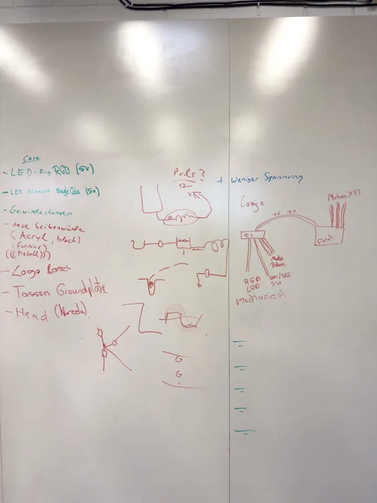
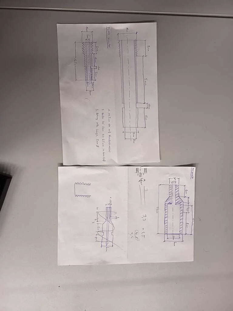
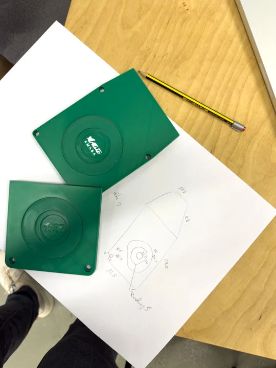
Planned and revised adapter parts
After the main components and especially the overall concept became clearer, the next step was to improve the provisional adapter solutions. For this, we had to decide which parts could simply be ordered, where a temporary solution would be sufficient, and which adapter pieces we had to manufacture ourselves. We initially planned and drew the necessary adapter parts before discussing their feasibility with the metalworker who could machine them on a lathe. This exchange was important because some ideas looked simple in the sketch, but were not necessarily practical or efficient to manufacture. Only after this discussion did it become clear which versions would actually be manufacturable. Based on this feedback, we revised our original plans and adapted the designs accordingly. This helped us move from improvised connections toward more reliable adapter solutions that better matched the mechanical and fluidic requirements of the machine.
Nico: 100%
William: 0%
Prepared last-minute component orders
We held numerous evening and late-night discussions to align on the current development status and identify which additional parts needed to be ordered within the next day—or even within a few hours—to address ongoing issues. This process helped us connect conceptual planning directly to immediate practical implementation steps. It also ensured that missing components could be sourced in time, allowing development to continue smoothly and issues to be resolved early.
Nico: 50%
William: 50%
Plumbing
Task group: Connect tubes and fluid components
Selected tube adapters
The water and milk path required suitable adapters between donor-machine parts, hoses, the pump, and the custom machine structure. We selected tube adapters and fittings so the reused components could become part of one connected fluid system. This was necessary because the donor parts were not originally designed for the geometry or hose layout of Artista Amara.
Nico: 70%
William: 30%
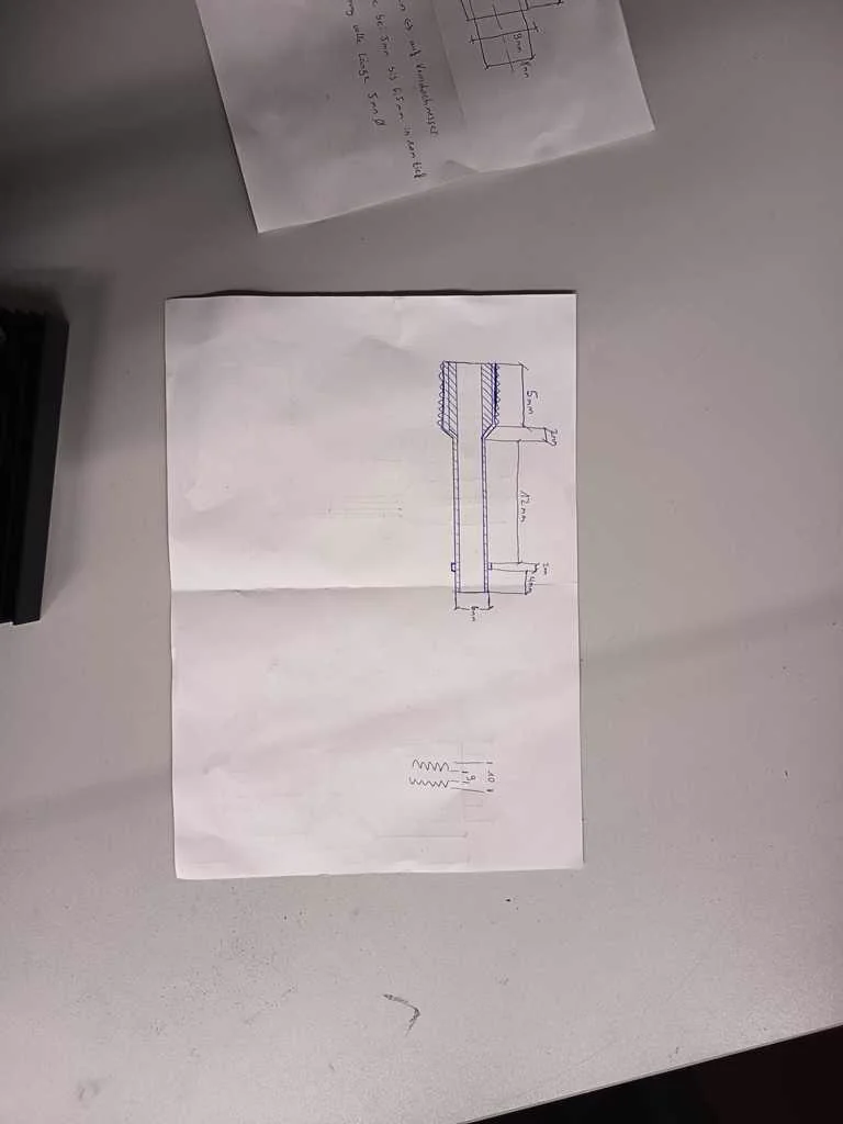
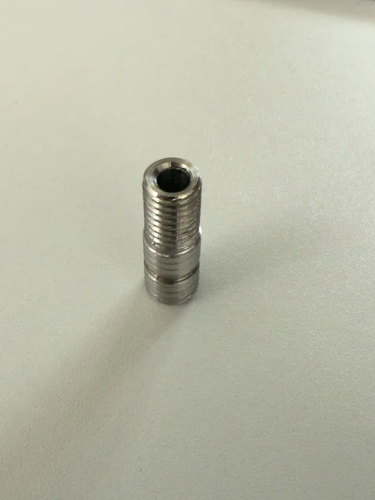
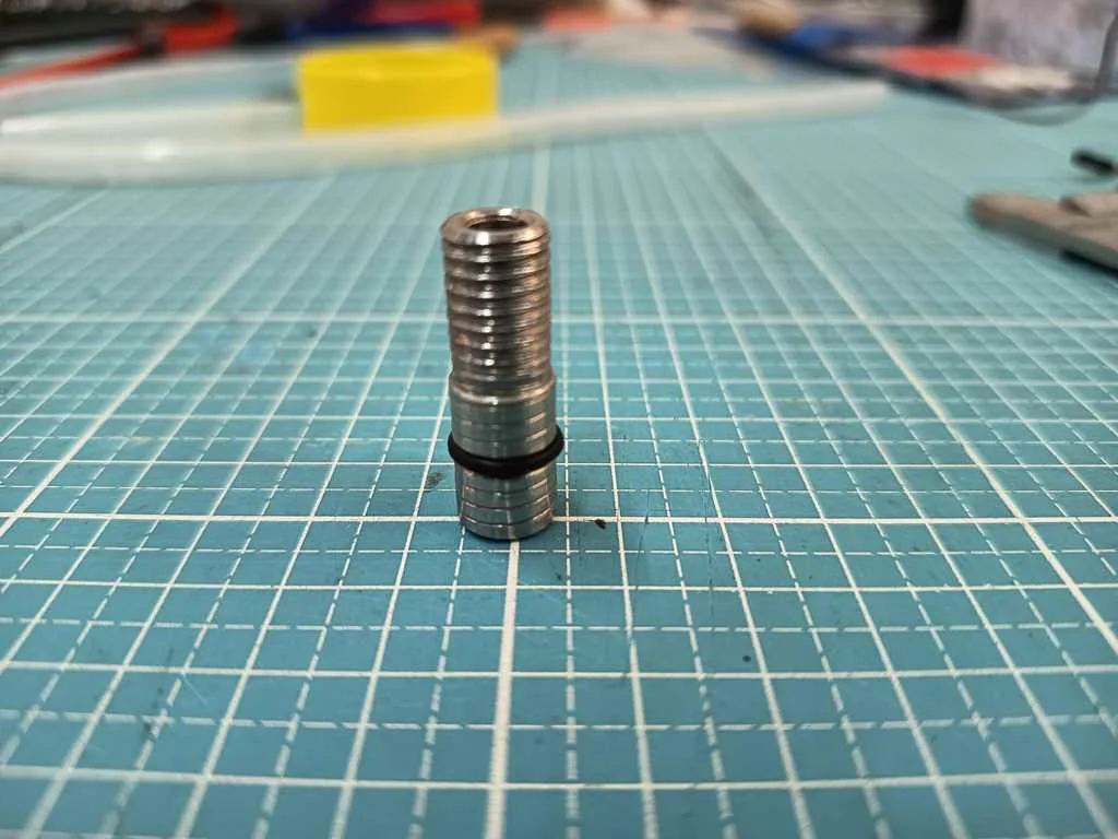
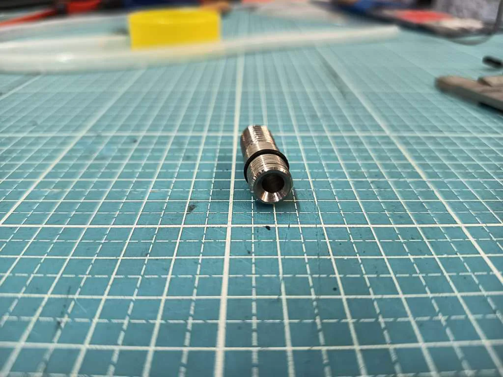
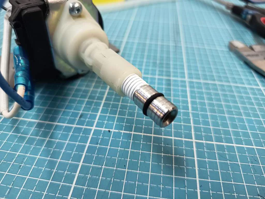
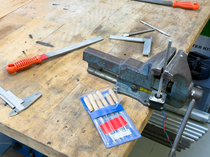
Turned hose adapters
Some connection parts had to be machined ourselves. In particular, we produced a stainless steel connection element to mechanically integrate the pump into the machine. This turned hose adapter made it possible to bridge the mismatch between reused coffee machine hardware and the custom tubing and mounting setup. We created new drawings for an adapter connected to the 3 mm air valve. These designs were intended to prepare the mechanical interfaces required for the planned fluid and air path. In this way, central connections of the later machine were translated into actual constructible parts.
Nico: 100%
William: 0%
Cut threads
Thread cutting was part of the custom adapter work needed for the fluid system. The machined connectors had to join securely to the surrounding fittings and hardware, so threaded sections were prepared where standard parts did not fit. This made the plumbing path more deliberate and reduced the dependence on temporary or improvised connections.
Nico: 100%
William: 0%
Connected devices with tubing
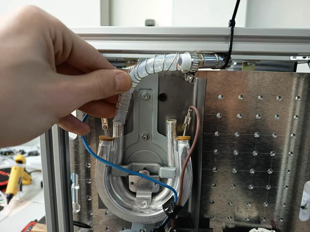
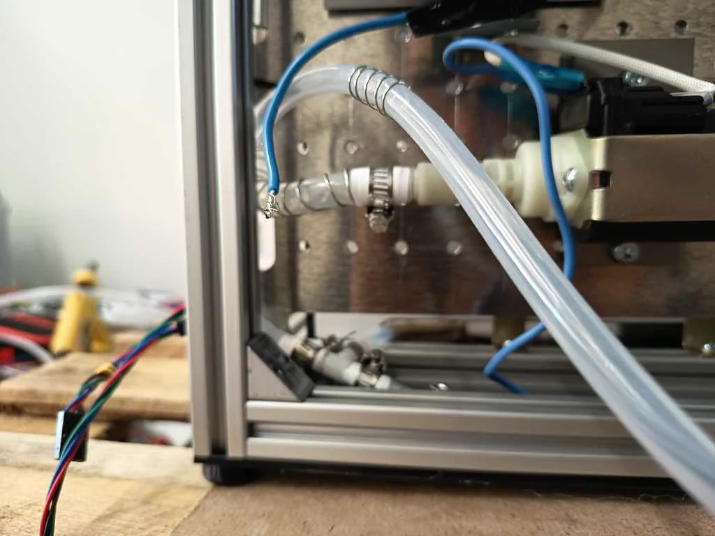
After selecting and machining the necessary adapters, we connected the fluid-related devices with tubing. The system had to link the tank, pump, heating or foaming elements, and nozzle path in a way that could later be controlled by the machine logic. Hoses and clamps were part of this step because the fluid path had to be stable enough for repeated tests. The water and milk connections had to be sealed after the tubing path was assembled. This was important because leaks would affect both the behavior of the machine and the safety of the surrounding electronics. This step turned the plumbing from a rough test setup into a more reliable subsystem that could be integrated with the pump and the foaming experiments. In addition to sealing the connections, we also reinforced the tubes with wire. This helped prevent the tubes from bending or kinking too much in tight radii, which could have reduced or blocked the flow inside the system. By sealing the connections and reinforcing the tubing, the fluid system became more stable and more suitable for further testing with water, milk, air input, and foam generation.
Nico: 100%
William: 0%
Built a cleaning station
We built some cleaning stations. This was necessary to complement the system not only functionally, but also in terms of maintenance, flushing, and hygiene. For a machine working with milk and foamed media, such a cleaning structure is an essential part of the overall concept.
Nico: 100%
William: 0%
Tests
Task group: Test machine behavior
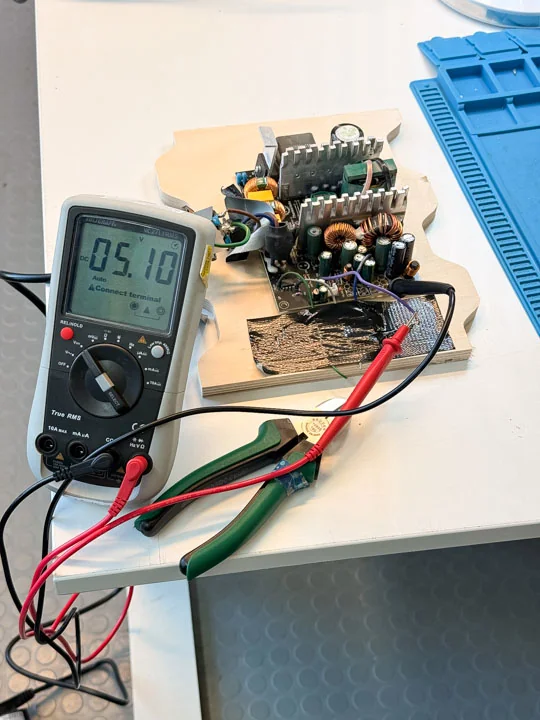
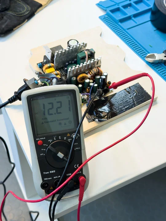
Tested PSU output
Before the machine could be assembled into a functional system, we checked the power supply levels. This helped verify that the available voltage rails were suitable for the planned electronics and actuators. Testing the PSU early reduced the risk of building later system layers on unstable or incorrectly understood power conditions.
Nico: 50%
William: 50%
Tested pump
We tested the extracted pump to determine whether it could be reused for the machine’s milk foaming function. This pump test was part of validating the donor hardware before integrating it into the system. It also helped us understand how the pump would behave when combined with milk, air input, tubing, and relay-based control. The testing was generally positive, as the pump was easy to control. However, the vibrations introduced some new issues, and the pump’s throughput was difficult to manage given the relatively low output required for our system.
Nico: 50%
William: 50%
Tested heating element
The heating element was tested separately as one of the key reused coffee machine components. This test helped confirm its electrical behavior and whether it could be considered for the milk preparation and foaming system. Because this part relates to higher-power operation, testing and later wiring had to be planned carefully. In addition to the basic electrical test, we also had to analyze the heat development of the heating element. For this, we used an IR thermometer to observe how quickly the component heated up and how the temperature changed during operation. This was important because the heating behavior directly influenced the later process timing. Based on these observations, we had to think about suitable on/off timing, process duration, and flow behavior. The milk or water should pass through the heating section in a way that allowed useful heating, without overheating the system or creating unsafe conditions. Therefore, the heating element was not treated as an isolated part, but as a component that had to be matched to the pump, flow rate, switching behavior, and overall process sequence.
Nico: 50%
William: 50%
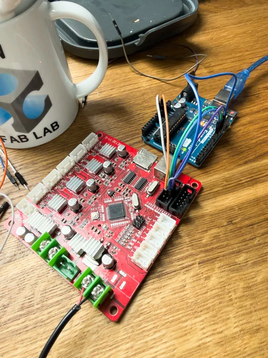
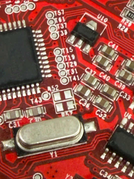
Reverse engineered ANET
We reverse engineered the ANET board to understand how it could be repurposed as a low-level controller. Several online guides were misleading, so the board had to be traced directly with a multimeter step by step. We measured all Output Voltage Levels on the Pins and traced connections from the ATMega back to the Testpads and Outgoing Pin Connections.
Nico: 30%
William: 70%
Ran blink test on ANET
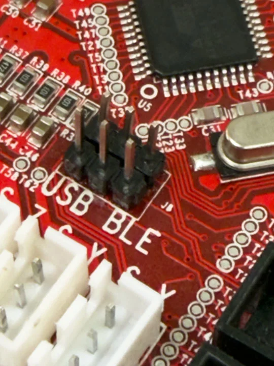
The blink test was part of the early ANET validation process. It helped confirm that the board could still be programmed and used in a non-standard setup. This kind of simple test was important before investing more time into firmware changes, serial communication, and relay-driven machine behavior. Since if we wouldve been unlucky the complete board might not been working at all. And as early test have shown there was indeed a problem with the board itself. During the ANET debugging process, we found that the onboard USB path could not be used as expected for our architecture. The CH340, the onboard USB serial converter chip seemed to be broken. But TX and RX Signals still ran threw the SoC which was an issue sind the forwarded onboard UART Pins on J3 were not working. To solve this, two resistors had to be removed and J8 had to be bridged so the serial communication path could be reconfigured for the Raspberry Pi-based setup. More details regarding that see here: Desoldered R52 and R53
Nico: 0%
William: 100%
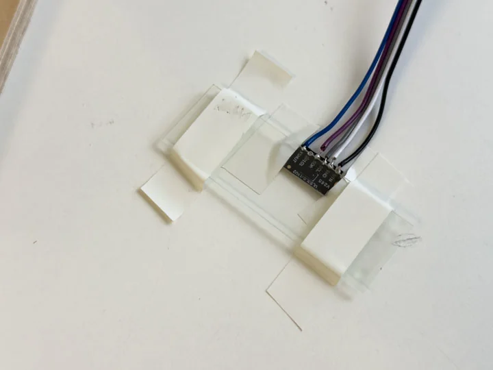
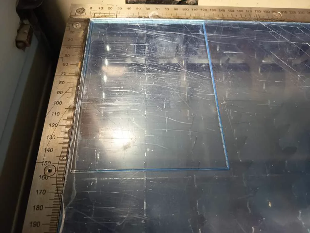
Measured through glass
We tested the measurement behavior of the ToF sensor through different glass, acrylic, and other transparent materials as part of the print head development. The sensor needed to reliably measure the milk or coffee surface while being protected from steam or occasional splashes, and it had to be integrated into the head assembly. This was directly related to the later integration of a glass cover for the ToF head. It turned out that chemical laboratory glass was the best choice, as its properties had almost no influence on the sensor measurements.
Nico: 50%
William: 50%
Measured coffee surface distance
was intended to use a ToF sensor before each print so it could adapt to different cups and fill levels. The measured value would be processed by the Raspberry Pi and translated into a motion offset before printing. As long as the liquid surface in the cup was calm, a reliable measurement was possible. This means that the sensor concept worked best when the coffee was not moving, vibrating, or disturbed by recent filling. For the machine logic, this was an important observation because the height measurement should ideally happen before the printing process starts and before any movement or fluid interaction creates waves on the surface. This test showed that a ToF-based height calibration could be a useful approach for adapting the nozzle distance to different cup and fill-level situations
Nico: 50%
William: 50%
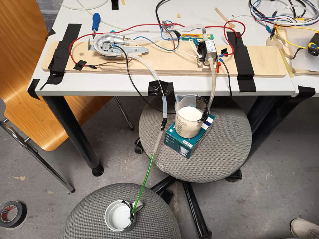
Infinite foaming up milk tests
We repeatedly carried out milk foaming tests using barista oat milk. These tests explored combinations of the pump, different screens such as bong screens and kitchen sieves, the heating element, nozzle variants, and different degrees of air input. Most results were negative or only partly successful, but the tests showed that usable foamed milk is possible if the relationship between open air valve and milk flow is controlled properly.
Nico: 80%
William: 20%
Tested nozzle with milk
The nozzle was tested with milk as part of the practical foaming and dispensing experiments. Several nozzle variants were considered because the machine did not only need to move over a cup; it also had to dispense a usable medium, while not destroying the foam. These tests connected the mechanical head design to the process question of how milk texture and flow behave in practice.
Nico: 80%
William: 20%
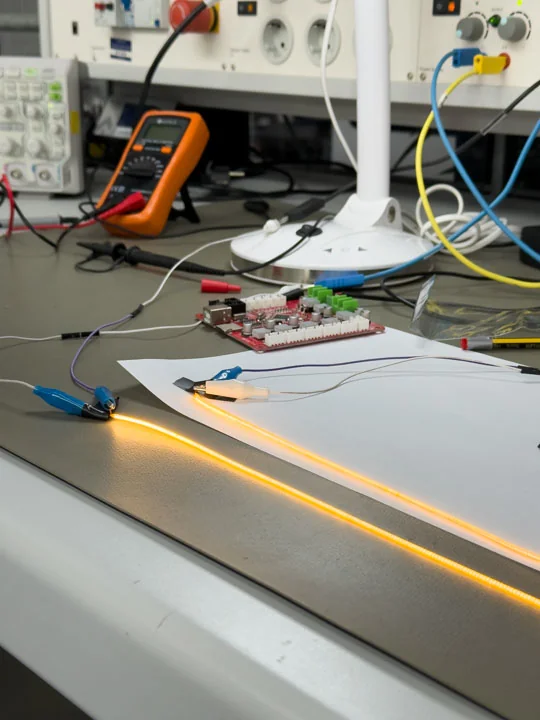
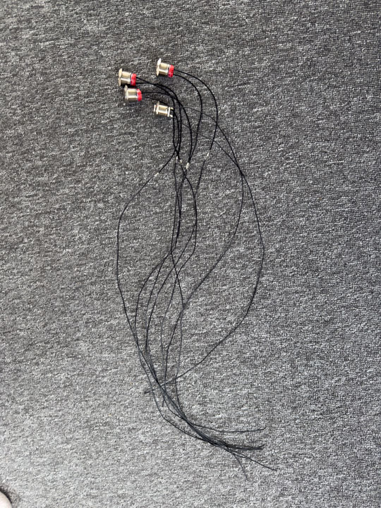
Tested Filament-LED voltage and current
We tested the voltage and current draw of the LED filaments as part of validating the electrical behavior of additional machine components. Lighting was included in the system to provide visual accents and head-area illumination. Measuring these values helped determine how the LEDs could be safely powered and controlled within the available voltage infrastructure. It was found that the 300 mm LED filaments drew approximately 80 mA at 3.3 V. Consequently, it was clear that they would need to be controlled via a relay rather than being connected directly to the Raspberry Pi pins.
Nico: 50%
William: 50%
Tested ESP32-S3 controller
Before settling on the Raspberry Pi-based approach, we explored a lighter microcontroller-hosted web structure. Initially we expected an ESP32 S3 to be somewhat able to host the webservice and interpret the users images into a functional GCODE. This route was eventually abandoned because it proved too slow and unstable for the overall complexity of the project. At this stage we were didnt even know that we would add that much additional logic in the end. But having the internal hardware validatet that early helped justify the switch to the Raspberry Pi Zero 2 W as the higher-level system controller and web host and making sure the other hardware solutions could be perfectly implemented an run on and besides the Pi.
Nico: 0%
William: 100%
Frame
Task group: Build the frame
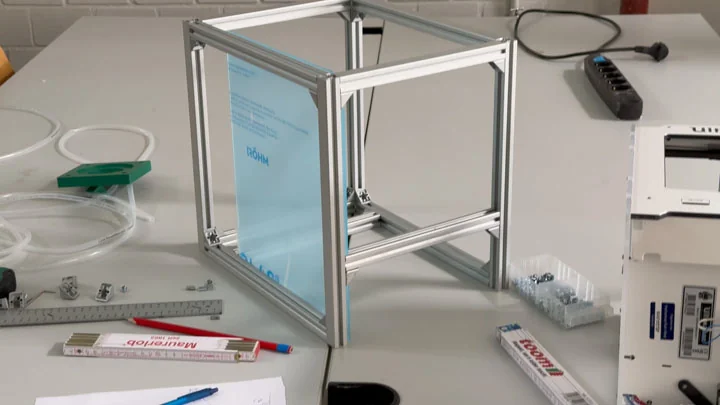
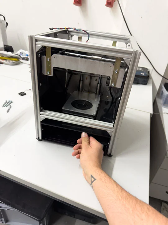
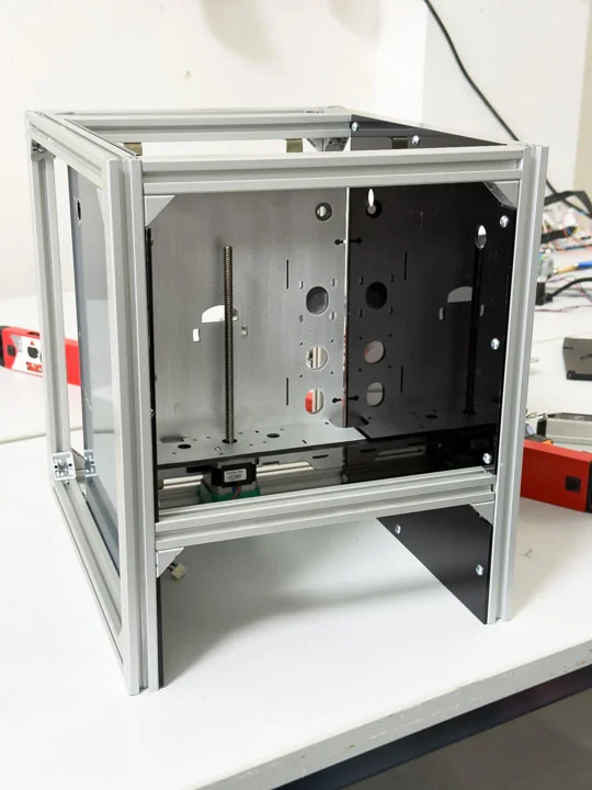
Cut frame poles
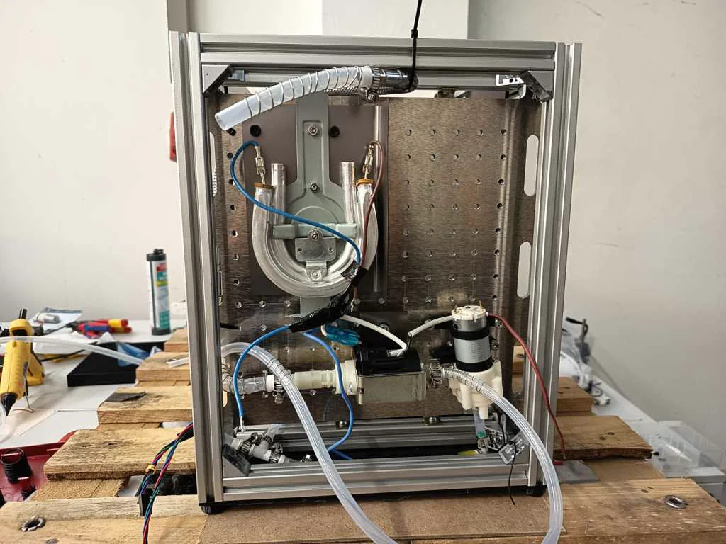
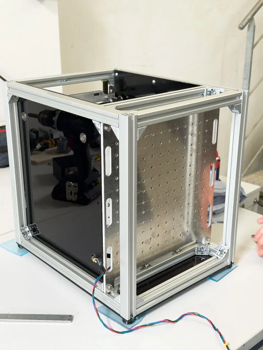
The frame was constructed from rods cut to various lengths. These frame poles defined the core structure of the machine while leaving sufficient space for tank handling, cable routing, electronics, and the external casing. The frame was treated as an evolving structure, as additional internal rods needed to be added as more components were integrated. The overall dimensions of the frame were approximately 33 × 35 × 28 cm.
Nico: 50%
William: 50%
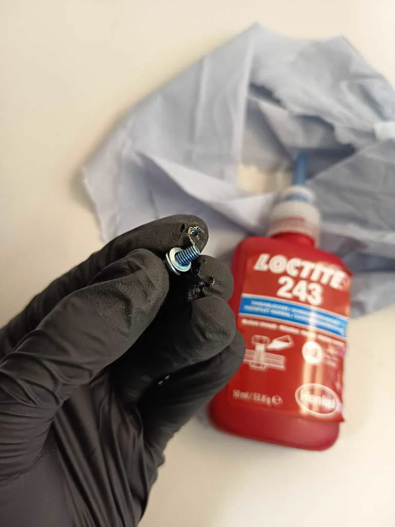
Inserted M4 nuts, screws and angle connectors
We assembled the frame using M4-based fastening hardware. The nuts and screws made it possible to build a structure that was rigid enough for motion control while still remaining adjustable during development. This was important because the machine geometry changed as more hardware was mounted and tested.
Nico: 50%
William: 50%
Rebuilt acrylic walls
We redesigned and rebuilt plexiglass inner walls for rod mounts and motor positions. These acrylic walls helped define the internal layout and gave the motion system a more stable structure. They also supported the transition from donor-machine geometry into a custom machine body.
Nico: 60%
William: 40%
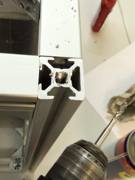
Added threads and feet
On the Systems base we added Threads to the metal frame. We designed feet within Houdini and printed them using TPU. They were added to improve the frame’s stability, positioning, and assembly quality. The machine needed to stand reliably while carrying the motion platform, cup bed, electronics, and case parts. The pump also introduces a lot of vibration which had to be accounted for. These smaller structural details helped turn the frame from a temporary assembly into a more usable machine base. The TPU Rubber Feet are surprisingly effective as the machine can not be moved by hand without lifting it up.
Nico: 20%
William: 80%
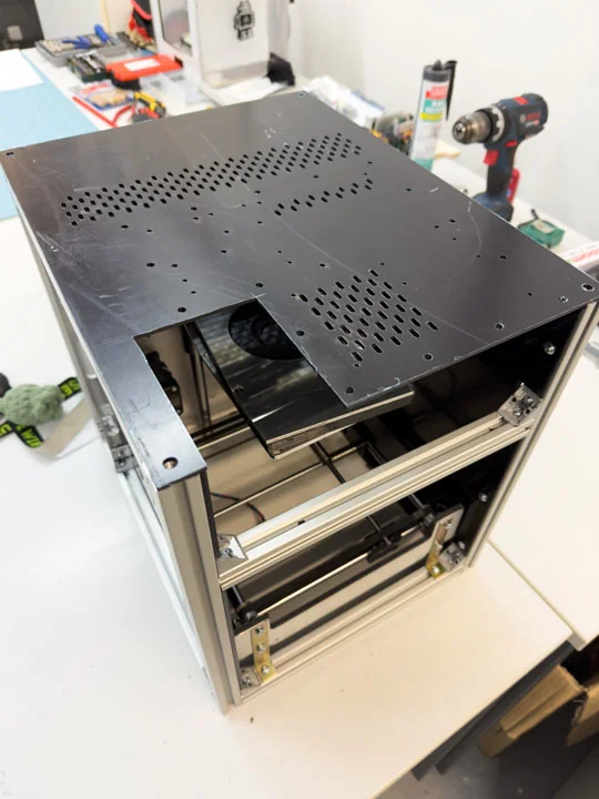
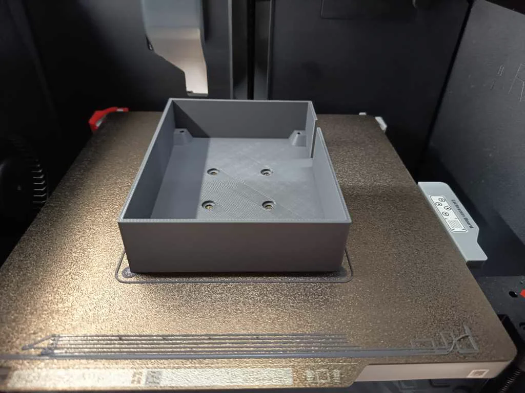
Added bottom printing room plate
The bottom printing room plate was added to define and support the area where the cup and print motion would operate. This is more of an optical modification as a pure technical one. The plate contributes still to the internal machine geometry and helped separate the functional print area from logic components of the machine as these are placed right below this plate. The plate functions as the sealing of the logic components as well as the Z Motor Stepper and overall cabling.
Nico: 0%
William: 100%
Added base plate
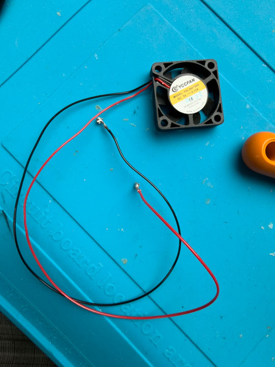
The base plate was added as part of completing the core frame structure. It supported the machine body and helped create a stable foundation for the axis hardware and surrounding components. It helped pulling the frame together and made sure the frame couldnt get loose anymore. This was one of the structural steps needed before the mechanics and electronics could be integrated more confidently.
When designing the baseplate for the system it was planned to hold all the logic components that run on 3.3, 5 or 12 Volts except for these that have an 240 Volts input (which is just true for pump and heaters relay). Every other logic component was planned and integrated onto the baseplate and could be mounted with M3 Screws. It had a spot for a small fan as well as a lot of venting points to make sure the system would overheat in a purely closed casing.
Nico: 0%
William: 100%
Motion
Task group: Build motion parts
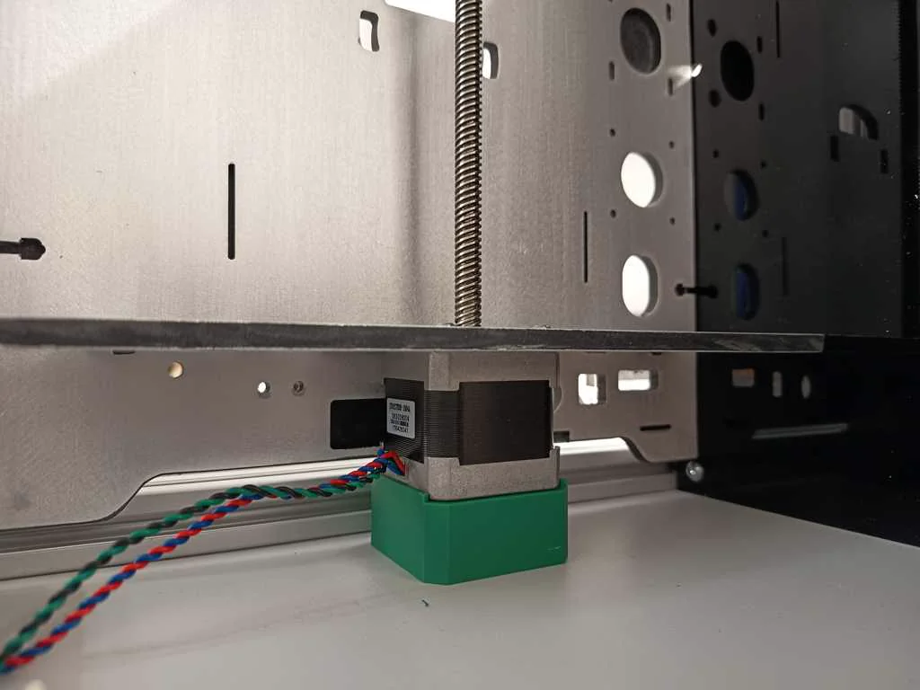
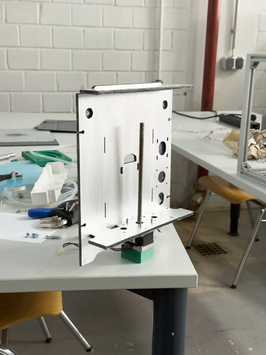
Raised Z [MK3] steppers
To make sure the Z-Axis motor would have a proper hold we printed a support stand making sure the motor would just be held by a few screws against the gravity. Since the bed would have to hold a filled Cafe Crema ~800g depending on mug and filling the support couldnt hurt. It was one of several changes required because the donor-machine layout did not directly match the latte art printer geometry. We also had to redo this step as we noticed some time during the process that our plan to use Ultimakers Stepper would be working at all.
Nico: 0%
William: 100%
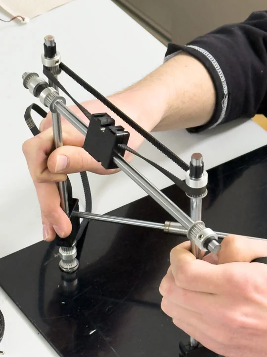
Used Prusa MK3 steppers
Changed JST to Molex; Shortened Z threaded rod; Shortened Y motor shaft; During testing we encountered an issue: The planned Ultimaker Stepper wouldnt be usable for our project as the run on 24 Volts. Our ANET Board on the other hand could only drive 12 Volt Steppers. We thought about replacing the onboard mosfets or replacing the full ANT Board. But after some thinking we came up with the idea to use old spare parts of the Prusa MK3 Printers. Their Steppers would also run on 12 Volts and would remove the problem entirely. As a sideeffect of switching the steppers the motor wiring had to be adapted so the selected motors could connect cleanly to the rest of the machine electronics. This meant changing the MK3s Molex connectors to JST Connectors since the ANET Board JST Connectors. Also the Z-Axis threaded rod had to be shortened and sanded before it could fit into the new machine geometry. The MK3s Z proportions are well over those found in an Ultimaker 2 Go which meant without this physical modification, the Z axis would not have fit or moved correctly in the available space.
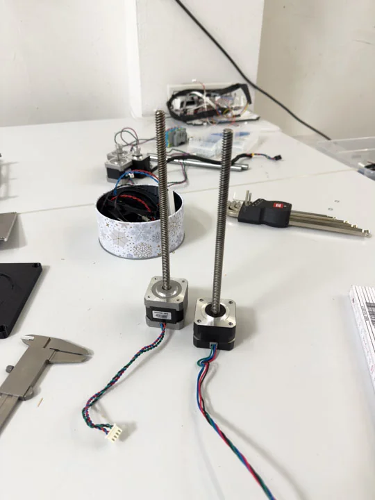
The Y motor shaft had to be shortened by several millimeters to prevent collision with the side wall. This small mechanical change was important because the machine body became tighter as panels, rods, and the motion system came together. The adjustment allowed the Y axis to fit within the final machine envelope.
Nico: 33.33%
William: 66.66%
Case
Task group: Build the case
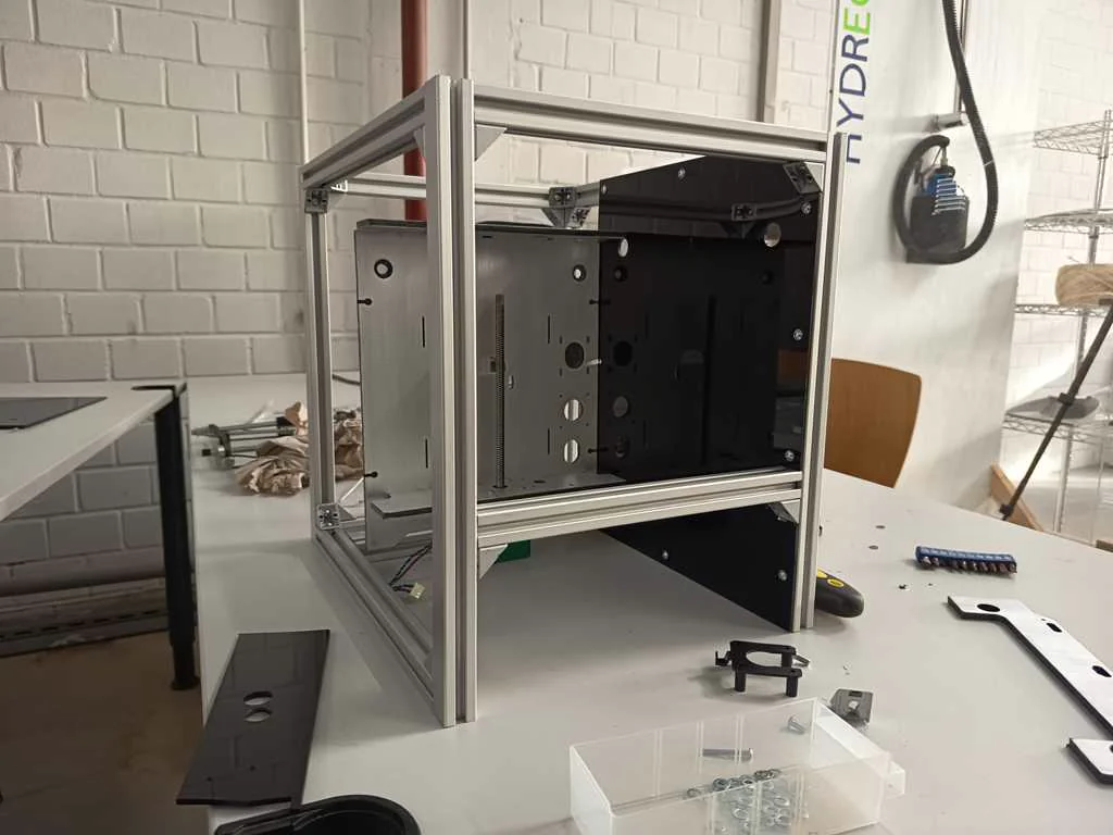
Cut Ultimaker panels
The old Ultimaker side panels were cut down so only the useful sections remained. This allowed us to preserve valuable donor-machine parts while adapting them to the new machine body. The panels became part of the visual and structural development of Artista Amara rather than remaining unchanged leftovers.
Nico: 100%
William: 0%
Exposed aluminum finish
To make our system look cleaner and more fitting we removed the white primer on the reused Ultimaker panels. To archive this we sanded away the primer to reveal the aluminum finish underneath. This was both a practical and aesthetic decision. It helped the machine move away from looking like a temporary assembly of salvaged parts and toward a more coherent identity.
Nico: 0%
William: 100%
Mounted side walls
As the machine body became more complete, the side walls were mounted and the front and rear sections were measured and installed using self bended brackets. This helped turn the internal frame into a more complete enclosure. The side wall mounting also connected the mechanical structure with the later casing and finish work.
Nico: 50%
William: 50%
Added holes and threads to rear plate
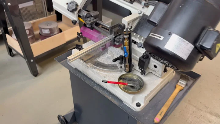
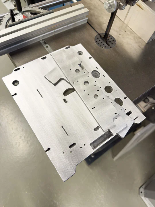
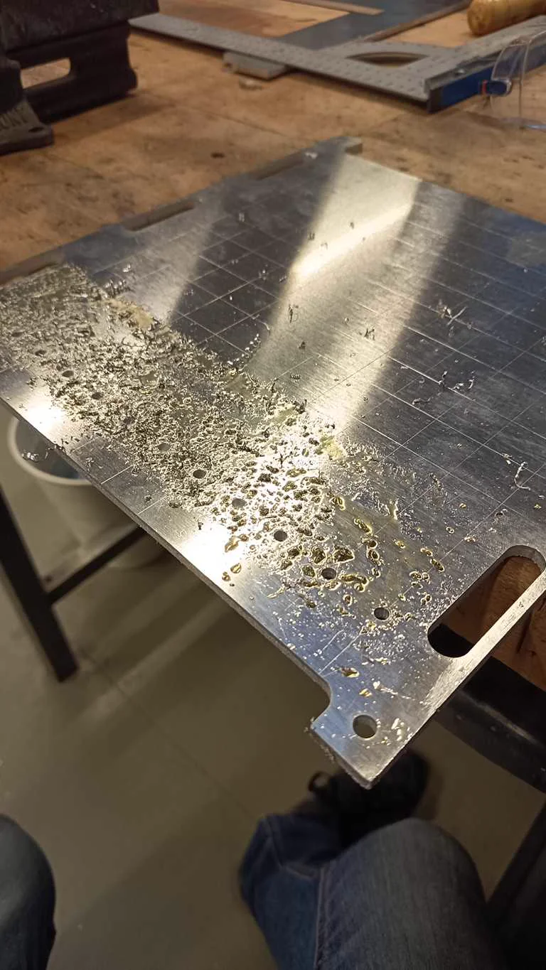
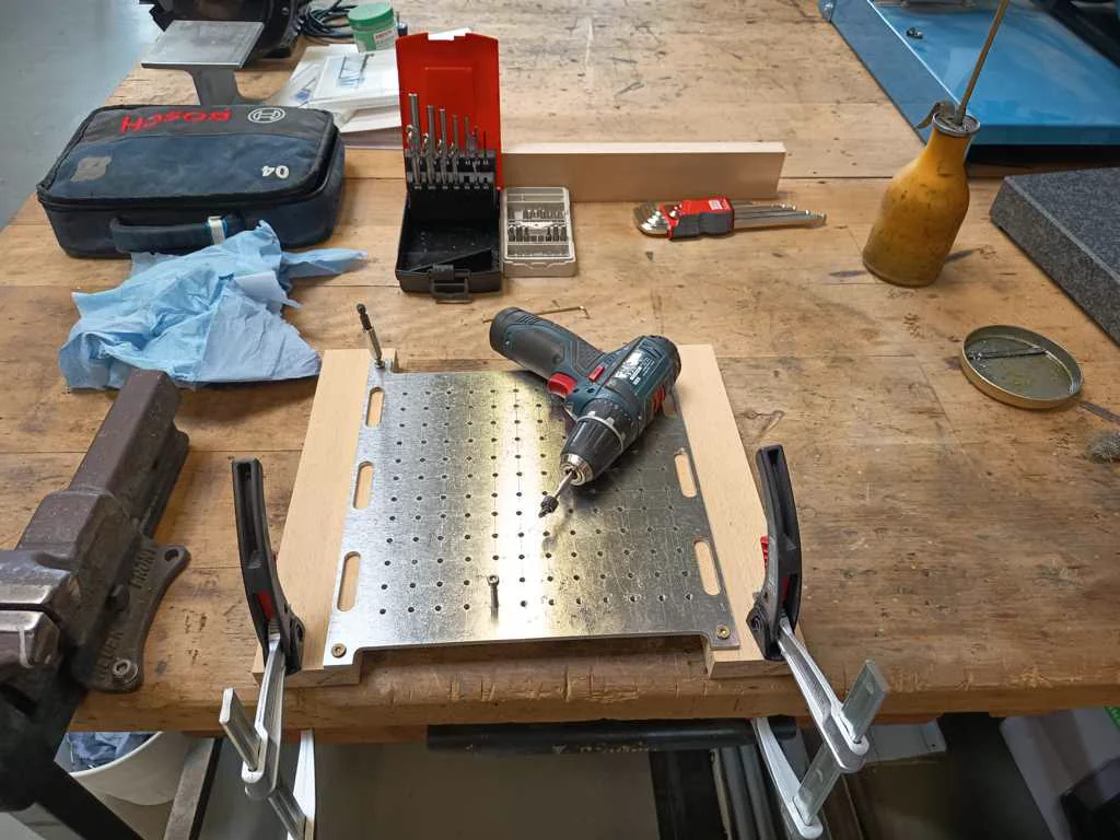
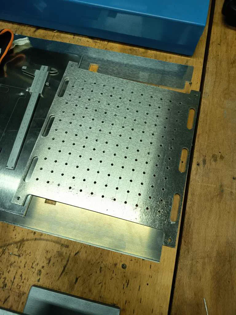
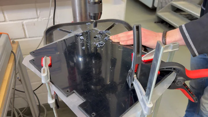
We planned to use a rear plate with a regular hole pattern as a mounting structure for the components on the back side of the machine. The idea was to create a stable and organized component area, where the high-voltage-related hardware and other technical parts could be spatially separated from the motion area. Our original plan was to manufacture this perforated rear plate with the metal laser cutter. However, this became much more difficult than expected. The main metal laser cutter in our lab had been out of operation for almost six months. A newly purchased smaller metal laser cutter was available, but it had not yet been properly commissioned.
During the cutting tests, a lot of slag built up at the piercing point of the holes. When the laser head completed the circular cut, it collided with this slag and repeatedly triggered a collision error. This happened even though the cutting parameters from the machine library should have been correct for the material.
Because of these problems, we changed the approach and started making the holes manually. After drilling the required holes by hand, we cut M5 threads into the rear plate so the components could be mounted directly and securely. In the end, this made the rear plate usable as a deliberate mounting subsystem, even though the manufacturing process required much more manual work than originally planned.
Nico: 100%
William: 0%
Designed PSU Case
We used a recycled PSU as the power supply for the machine. However, the original housing did not fit our machine layout, so we had to cut off part of the original case to integrate it into the rear component area. Because this exposed the PSU more than in its original condition, we designed a custom case for it. The goal was to make the PSU safer to use and easier to mount. The case was designed so it could be attached quickly and simply to the rear plate of the machine. The enclosure protects the PSU itself, but it also protects the potential user. Without a proper case, someone could accidentally place their hand directly on exposed electrical contacts. For this reason, the PSU case was an important safety-related part of the rear electrical area and helped separate the power hardware from the motion and print areas of the machine.
Nico: 100%
William: 0%
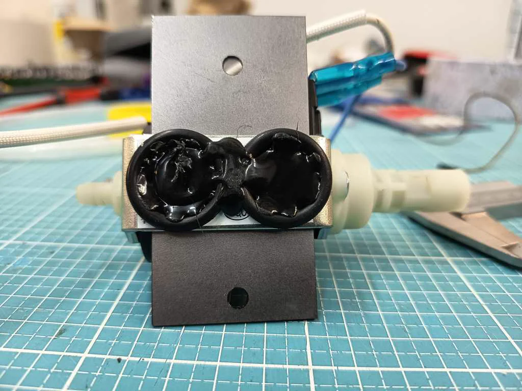
Built heating element case & pump brackets
The heating element mounting was part of integrating the reused heating hardware into the machine body. Because the heating element belongs to the higher-power and heat-generating side of the project, it needed a more deliberate mounting and shielding strategy. For this, we shielded the heating element with a 2 mm steel sheet and reused the existing holder of the component. To mount it properly into our machine structure, we drilled new holes with the correct spacing for our perforated metal plate. After that, the heating element and its shielding could be mounted more cleanly and safely in the rear component area of the machine. The pump mounting was designed to hold and integrate the extracted pump within the machine. The pump had to connect mechanically to the custom adapters and the fluid path, while also being controlled through the machine’s relay logic. Instead of leaving it as a loose test component, we built a dedicated mounting solution. For the pump, we laser-cut two 2 mm steel sheets with matching holes for the screws. These plates were used to fix the pump in place. To reduce direct vibration transfer into the machine frame, we added two slightly larger O-rings between the mounting parts as a simple vibration-damping solution. This made the pump integration more stable and better suited for the final build.
Nico: 100%
William: 0%
Designed outer walls
The outer side panels were planned to be cut from acrylic and covered with veneer to give the machine a more finished shell. These outer walls were intended to integrate openings and placements for machine buttons, combining casing design with interface hardware. This step would have helped turn Artista Amara into a more coherent prototype both visually and mechanically. However, due to time constraints, this implementation could not be completed during the build phase.
Nico: 0%
William: 0%
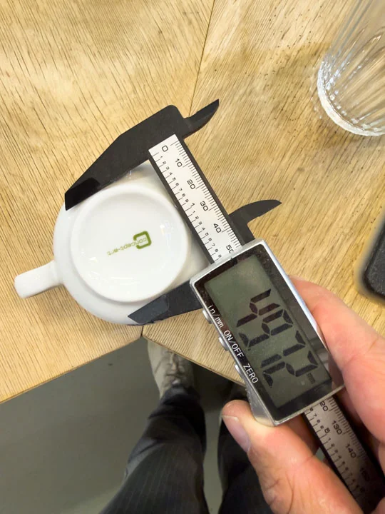
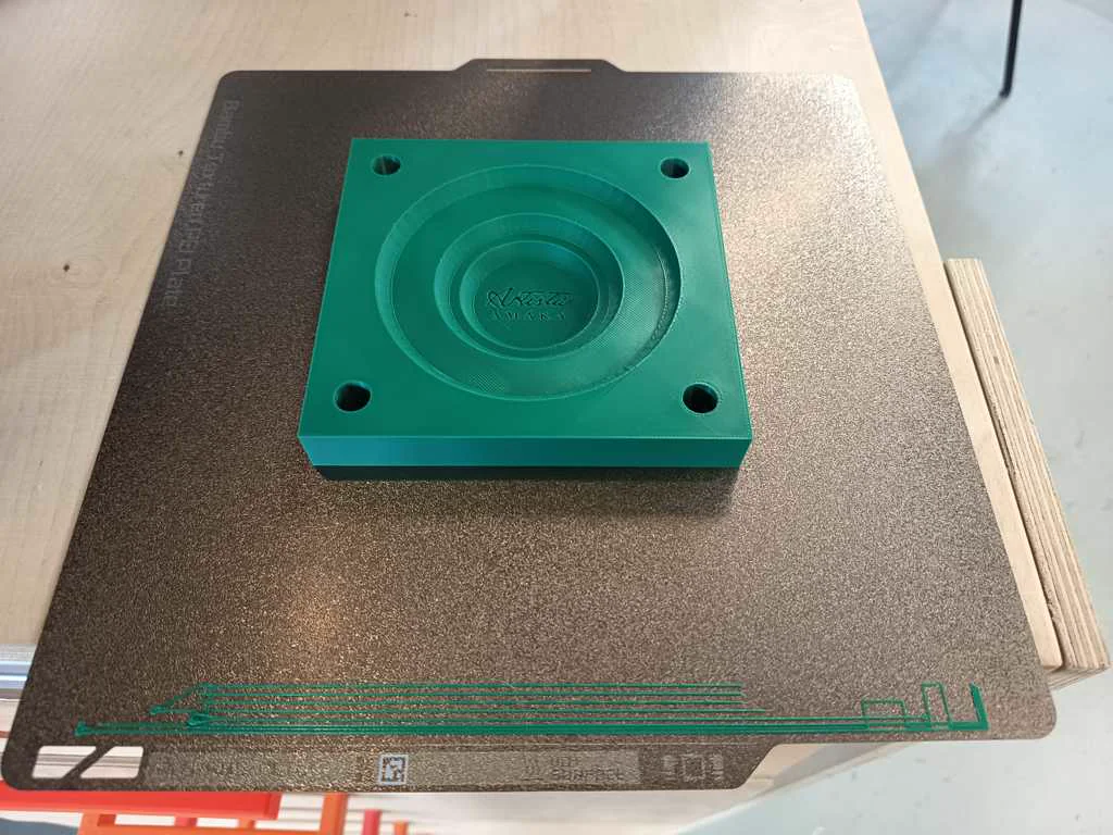
Designed mug bed
The original printing space wasnt meant to hold a cup - or serval different cupssizes within a heavily vibrating machine. So we designed a cup bed to hold our labs cups. We went through multiple iterations. It had to support the cup reliably while integrating into the rest of the machine and motion system. We changed just a few tenth of a mm until we got the perfect fit. During this process the mug bed was first printed in PLA as part of a fast prototyping process. This helped check geometry and fit while maintaining a fast buildtime. After archiving exactly what we have been looking for it was time to print the final cup bed in 90A TPU. This material choice made sense because the bed had to support the cup while still allowing a more forgiving contact surface and negating the negative effect of vibrations. The TPU base was later combined with a metal top plate to improve the quality and finish of the cup area.
Nico: 0%
William: 100%
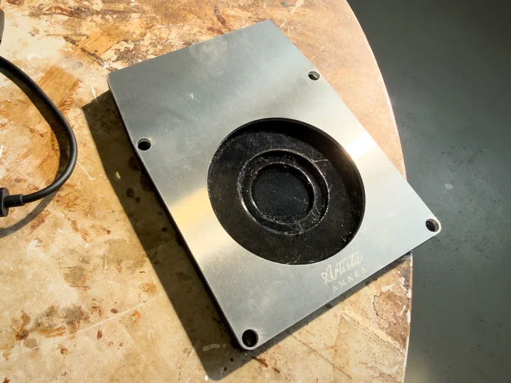
Engraved mug bed logo plate
A metal top plate for the mug bed was produced in the Metal Fab and engraved with a logo. The plate was then bonded to the TPU base using two-component adhesive. This improved the finish of the cup area and added a recognizable detail to the machine’s visual identity.
Nico: 50%
William: 50%
Head
Since we are not aiming for a standart FDM Printer we couldnt reuse the old Head entirely. So we had to design our own that fitted our needs. It had to hold a ToF Sensor for Height Data as well as an (optional) glass cover. For usability reasons we also added an LED Ring to give some user feedback. And last but not least we also had to integrate the nozzle as usual which draws the latte art pattern. The head was created using PETG FDM Printing.
Integrated ToF sensor
The print head was designed to integrate the ToF sensor. The sensor was intended to measure the milk surface before printing so the machine could calculate the correct print height as well as making sure everything is positioned correctly as another safety feature. The ToF is connected to the Raspberry Pi because the measured value needs to be processed in software as a motion offset. The ToF sensor was implemented with a pressfit solution allowing of fast changing when it breaks as well as some cable management to the top side of the head.
Nico: 15%
William: 85%
Prepared glass cover for ToF
*Initially we planned on implementing a glass cover for the ToF sensor area so the sensor could be protected from steam and therefore damage while remaining usable for measurement. This connected directly to the tests where we measured through glass. The goal was to make sensing robust enough for the environment around milk foam, coffee, steams, and the moving print head. However due to time issues this step was skipped unfortunately.
Nico: 20%
William: 0%
Prepared LED ring
The LED ring was prepared as part of the print head and sensing area. It provided illumination around the nozzle and sensor, supporting both the visual quality of the head and the practical use of the machine. The LED Ring is also attached with a press fit solution also allowing a quick replacement.
Nico: 0%
William: 100%
Integrating nozzle
The nozzle was prepared as one of the key elements of the compact print head assembly. In our concept, the 4 mm stainless steel nozzle was placed together with the ToF sensor and the LED ring. This setup combined several functions in a small area. The nozzle dispensed the prepared medium onto the coffee surface, while the motion system moved the head accurately across the cup. The ToF sensor supported height measurement, and the LED ring provided visual feedback. Because of this, the nozzle was integrated as part of the full print head concept, not as a separate component.
Nico: 100%
William: 0%
Logic Circuit
Task group: Build the logic circuit
Desoldered R52 and R53
As part of reworking the ANET board communication path, two resistors had to be removed. An online documentation explains that the onboard USB chip is still being electrically preferred, so removing these resistors and bridging J8 allows the serial communication path to be reconfigured. However bridging the pins mentioned online did not work for us. We had to trace the individual wires back to the UART Pins on the MCU to realize that the documentation has some wrong parts. In the picture below you can find a instruction based on our learnings. However I recommend measuring your boars wires as this seems to be different depending on your boards version or even manufacturing sample. This step was crucial for the board to fit into the Raspberry Pi-based machine architecture.

Nico: 0%
William: 100%
Configured Marlin for ANET
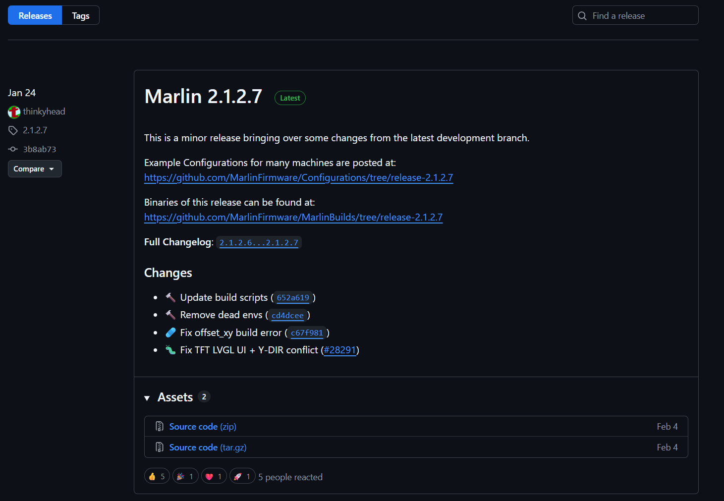
The starting point was Marlin 2.1.2.7, using the official ANET A8 example configuration as a base. This example already targets the correct board definition (BOARD_ANET_10) and sets the ATmega1284P as the target MCU, so no changes to platformio.ini or the board file itself were necessary. All meaningful changes were made exclusively in Configuration.h and Configuration_adv.h. Marlin Download Marlin was downloaded as version 2.1.2.7, which is the current stable release as of early 2026. The firmware itself and its example configurations are maintained in two separate GitHub repositories, both of which are needed: Firmware source: https://github.com/MarlinFirmware/Marlin — the core firmware code Example configurations: https://github.com/MarlinFirmware/Configurations — board-specific Configuration.h and Configuration_adv.h files
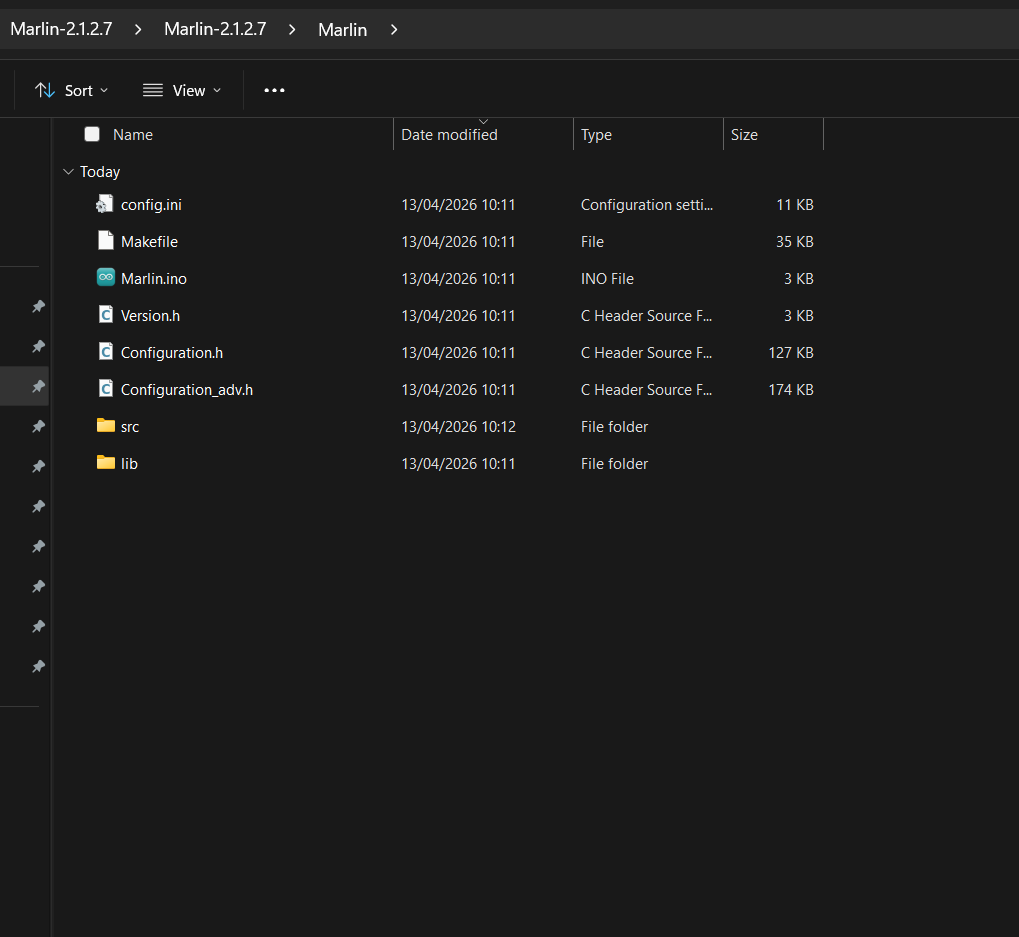
The process was to download both as ZIP archives and then copy the ANET A8 example configuration files into the Marlin source tree, replacing the generic placeholder files: Configurations/config/examples/Anet/A8/Configuration.h Configurations/config/examples/Anet/A8/Configuration_adv.h These two files get copied directly into the Marlin/ subfolder of the firmware source. This is the recommended starting point rather than editing the blank defaults, as the ANET A8 example already has the correct board definition, pin assignments, and driver settings pre-filled. From there, only the project-specific changes described above needed to be made
**Print Size
The physical build volume of the machine was defined in Configuration.h through the axis travel limits. The ANET A8 example ships with the original printer dimensions — a 220 × 220 mm bed with 240 mm Z height — which served as the starting reference. For Artista Amara, these values were adjusted to match the actual working area of the Ultimaker 2 Go. Feedrate and Speeds Feedrates in Marlin define the upper limits at which any axis is allowed to move. G-code commands can only request speeds at or below these firmware maximums — if a command exceeds the limit, Marlin silently clamps it down. This means the firmware values act as a safety ceiling, not a default operating speed.
The relevant settings are split across a few parameters in Configuration.h:
// Maximum speed each axis can reach (mm/s)
#define DEFAULT_MAX_FEEDRATE { 150, 150, 10 }
// X    Y    Z
// Maximum acceleration (mm/s²) — how fast the axis ramps up to speed
#define DEFAULT_MAX_ACCELERATION { 1500, 1500, 100 }

// Default starting acceleration for moves
#define DEFAULT_ACCELERATION         800
#define DEFAULT_TRAVEL_ACCELERATION  800
For Artista Amara, the X and Y speeds were kept moderate rather than maximized. The latte art patterns require smooth, consistent motion — especially at direction changes — since any vibration or jerk translates directly into irregular milk flow. The Z axis was set conservatively at 10 mm/s since Z movement only happens during initial positioning, not during printing.
Jerk settings control how abruptly the machine can change direction without pausing to decelerate. Lower jerk means smoother corners at the cost of slightly longer travel times:
#define CLASSIC_JERK
#define DEFAULT_XJERK  5.0
#define DEFAULT_YJERK  5.0
#define DEFAULT_ZJERK  0.4
The actual print speed sent by the Pi during a run is set via the F parameter in each G1 move command and can be tuned independently per pattern without reflashing — as long as it stays below the firmware ceiling: G1 X100 Y50 F3000 ; move at 50 mm/s (3000 mm/min)
**Axis Setup
The ANET A8 example configuration ships with four-axis settings by default, meaning every array-based parameter includes an E0 (extruder) value as its fourth element. Since Artista Amara has no extruder, these arrays had to be trimmed to exactly three elements. Marlin’s SanityCheck.h enforces this at compile time and throws static assertion errors otherwise — which is exactly what was seen in the initial failed build. The relevant arrays were corrected to three-element form:
#define DEFAULT_AXIS_STEPS_PER_UNIT   { 80, 80, 400 }
#define DEFAULT_MAX_FEEDRATE          { 300, 300, 5 }
#define DEFAULT_MAX_ACCELERATION      { 3000, 3000, 100 }
#define AXIS_RELATIVE_MODES           { false, false, false }
**Temperature Sensors
Marlin requires a valid thermistor type for every heater it manages. Without a connected thermistor, it goes into thermal runaway immediately and locks the corresponding output pin. Setting both sensor values to 0 tells Marlin that no thermal hardware is present at all, which fully disables the temperature management subsystem for those channels:
#define TEMP_SENSOR_0    0
#define TEMP_SENSOR_BED  0
In addition, the thermal protection features were disabled. While these are important safety features in a real 3D printer, they serve no purpose here and would otherwise block access to the heater output pins entirely:
//#define THERMAL_PROTECTION_HOTENDS
//#define THERMAL_PROTECTION_BED
**LCD / Display
This was the most impactful setting change. The ANET A8 example configuration ships with ANET_FULL_GRAPHICS_LCD enabled by default. When any LCD type is defined, Marlin’s display driver takes permanent ownership of all EXP1 header pins and continuously drives them as part of the display communication cycle. This made it impossible to use M42 to control those pins freely — the firmware would simply override any value written. All display definitions were commented out:
//#define ZONESTAR_LCD
//#define ANET_FULL_GRAPHICS_LCD
//#define ANET_FULL_GRAPHICS_LCD_ALT_WIRING
//#define REPRAP_DISCOUNT_FULL_GRAPHIC_SMART_CONTROLLER
A secondary effect of disabling the LCD is that Marlin’s pin file falls into its #else branch and automatically assigns SERVO0_PIN to EXP1_08_PIN (D27). This was the reason M42 P27 S255 was toggling the onboard D0 LED instead of the physical header pin — the pin was silently claimed as a servo output. Disabling the LCD definition resolved this entirely.
**Pin Debugging
M43 is an optional Marlin feature that allows toggling and monitoring individual pins over serial at runtime, which is extremely useful for verifying that a given pin number actually corresponds to the expected physical pad. It is not compiled in by default and must be explicitly enabled in Configuration_adv.h:
#define PINS_DEBUGGING
With this enabled, a command like M43 T P28 toggles D28 between HIGH and LOW repeatedly, making it trivial to confirm relay response with a multimeter or by observing the relay module LED.
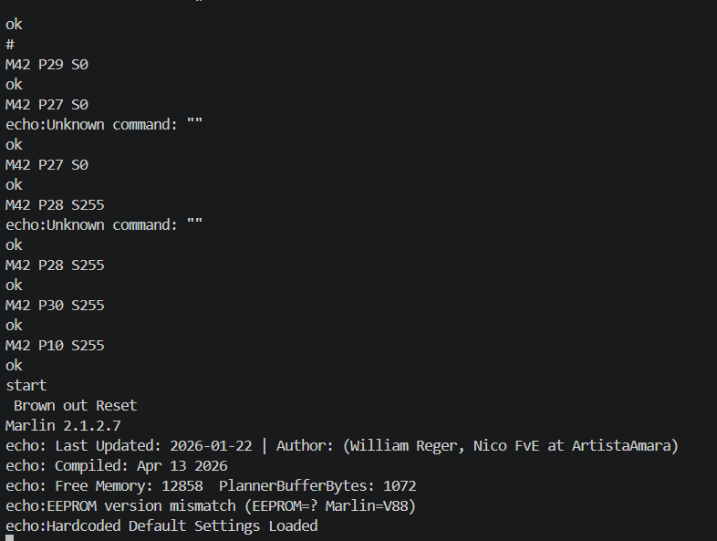
Startup Commands One issue that surfaced during testing was that all EXP1 pins power up as inputs with internal pull-ups enabled, meaning they sit at 5V on boot before Marlin has had a chance to configure them as outputs. For active-LOW relay modules, this causes every relay to momentarily fire during startup. To prevent this, STARTUP_COMMANDS was defined to immediately drive all relay pins LOW as the very first action after boot:
#define STARTUP_COMMANDS "M42 P10 S0\nM42 P11 S0\nM42 P16 S0\nM42 P17 S0\nM42 P28 S0\nM42 P29 S0\nM42 P30 S0"
This ensures that regardless of relay module polarity, no unintended switching occurs during the board’s startup sequence.
Nico: 0%
William: 100%
Flashed Marlin
PlatformIO as the Build Environment
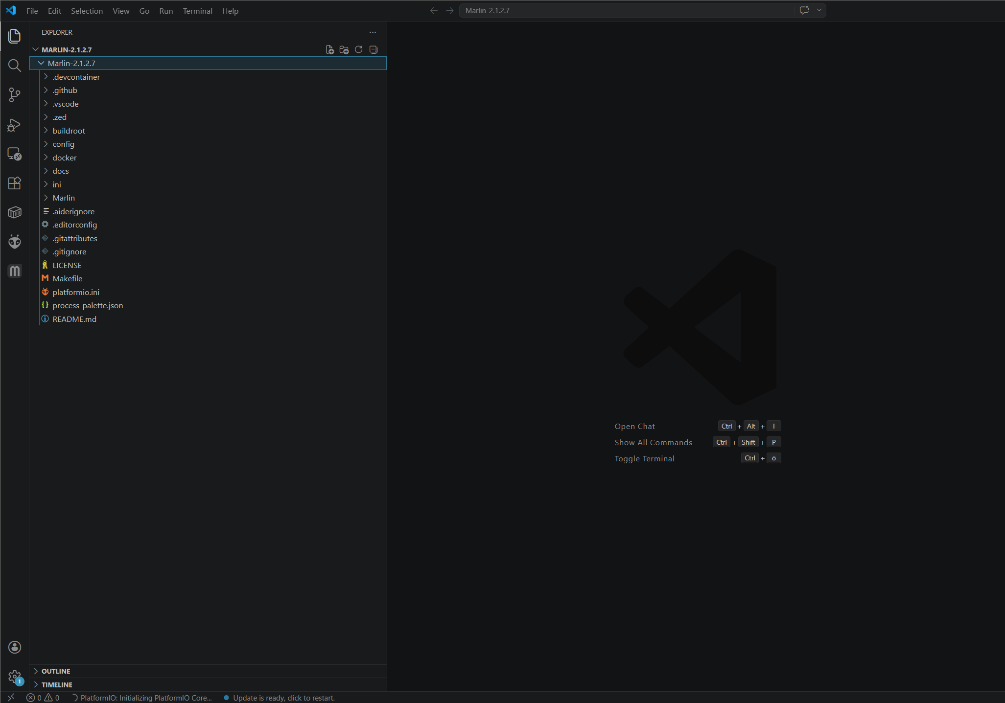
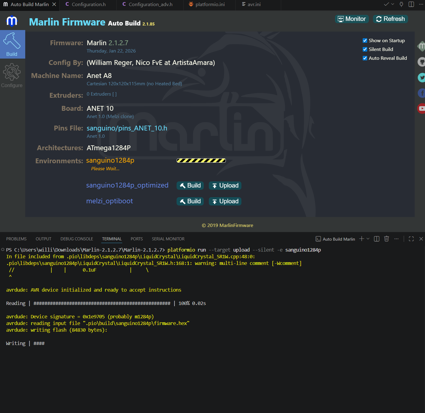
Rather than using the Arduino IDE, the build and upload process was handled entirely through PlatformIO, which integrates cleanly with VS Code and offers better dependency management and build reproducibility. The ANET A8 board target is defined in platformio.ini under the sanguino1284p environment, which tells PlatformIO to use the AVR toolchain targeting the ATmega1284P: [env:sanguino1284p] platform = atmelavr board = sanguino1284p framework = arduino Before the first successful build, PlatformIO automatically fetched and installed the required upload tool: Tool Manager Installing platformio/tool-avrdude 1.60300.0 Downloading [100%] Unpacking [100%] tool-avrdude@1.60300.200527 has been installed! With the configuration files in place, the firmware was compiled using: platformio run -e sanguino1284p This produced the final .hex file ready for flashing. Any configuration errors — such as the array size mismatches seen in the early builds — showed up at this stage as compiler errors before anything was written to the board, which made iterating on the configuration safe and fast.
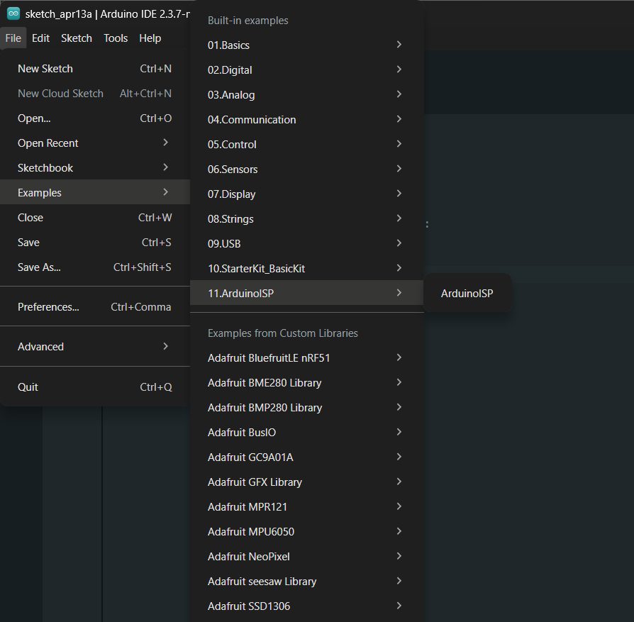
Flashing via ISP Bridge Because the onboard USB path through the CH340 proved unreliable for programming, the board was flashed using an Arduino as an ISP programmer. A standard Arduino was loaded with the ArduinoISP sketch, connected to the ANET board’s 6-pin ISP header, and used as a bridge between USB and the ATmega’s SPI programming interface. The upload was then triggered directly through PlatformIO with the ISP programmer selected as the upload method: platformio run –target upload -e sanguino1284p
After a successful flash, the board was immediately tested over serial via the J3 header at 250000 baud, confirming that Marlin had started correctly and was responding to simple G-code commands.
Nico: 0%
William: 100%
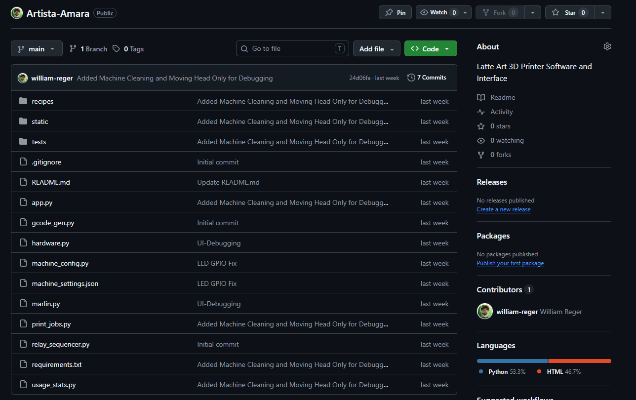
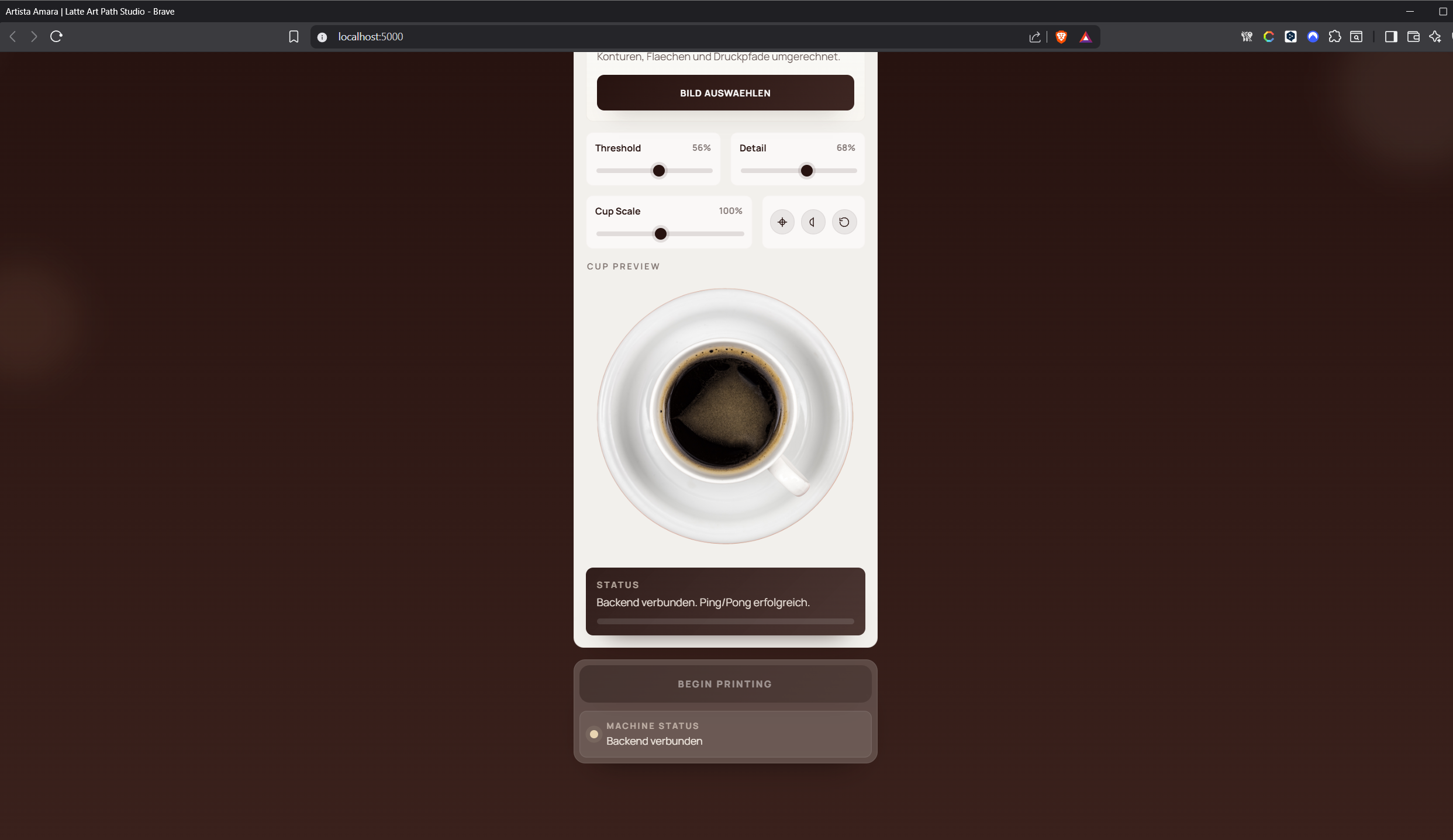
Built Raspi website
We created a web-user interface that serves as a mobile-first, single-page control center for the Artista Amara latte-art machine. Driven by a Python Flask backend, the application seamlessly coordinates the user interface, a Marlin motion controller, GPIO hardware, customizable recipes, and usage statistics. The core experience revolves around the “Latte Art Studio,” where users can upload images or SVGs, select presets, or generate text-based artwork. Within the browser, the frontend utilizes canvas logic to trace the artwork, apply adjustments like threshold, detail, and cup-scale, and verify that the design perfectly fits the selected cup. It then renders both a machine-coordinate and a physical cup preview. When a print is initiated, the browser transmits these traced paths to the backend, which translates them into a precise G-code hatch fill utilizing G0, G1, and M42 commands for pump and valve control.
Behind the scenes, the backend acts as the central orchestrator to safely execute these commands. A dedicated print job manager ensures that all safety conditions—such as the system switch and tank state—are met before homing the machine, reading the Time-of-Flight (ToF) distance sensor to set the Z-axis reference, and streaming the G-code over serial UART to the Marlin board. Throughout this process, communication flows across two distinct layers: standard HTTP requests handle discrete actions and configuration updates, while a real-time Socket.IO connection pushes live telemetry, print progress, sensor readings, and hardware states directly to the browser.
Beyond straightforward printing, the interface features an Advanced area that functions as a comprehensive machine control center. Here, operators can edit JSON-based foam and cleaning recipes, adjust machine geometry, manually jog the motion system, and run system diagnostics. The application also incorporates strict built-in safety mechanisms; if the physical system switch is turned off, print jobs and active hardware sequences are immediately blocked, while missing tank states trigger instant UI warnings. Additionally, post-print usage statistics can prompt automated cleaning workflows, which subsequently unlock manual overrides for service and maintenance. Ultimately, this platform goes far beyond a simple upload page—it is a fully integrated operator panel that unifies artwork preparation, G-code generation, live hardware telemetry, and rigorous safety management into a single, cohesive web application.
Nico: 0%
William: 100%
Built G-code conversion
We create a system that transforms prepared artwork—whether from uploaded images, SVGs, presets, or generated text—into machine-readable movement and relay commands to run our Artista Amara. The process begins in the frontend, which converts the chosen design into closed vector paths that represent the filled areas to be printed. Once the user initiates a print, the browser transmits these paths to the /api/gcode endpoint, along with specific parameters such as cup size, scaling, canvas size, feed rates, and device patterns. The backend then takes over, mapping the digital 768-by-768 coordinate system into real-world millimeters based on the configured print center and cup diameter. Because the generator treats the design as solid shapes rather than mere outlines, it relies exclusively on closed paths to apply a precise horizontal hatch-fill algorithm. During this step, evenly spaced horizontal scan lines—typically matching the nozzle diameter—cross each polygon. The system calculates and sorts the intersection points along the edges, pairing them into printable segments. To physically draw the design, the generated G-code orchestrates a highly synchronized sequence: it uses a G0 command to travel to the start of a segment, triggers M42 pin commands to open the flow path and activate the pump, executes a G1 move to draw the line, and finally shuts off the pump and closes the flow stop before moving to the next segment. To optimize the printing process and reduce unnecessary travel time, the scan rows alternate direction. The resulting G-code file is fully self-contained, initiating with G21 for millimeters and G90 for absolute coordinates, and concluding with an M400 command that safely returns the machine to its idle relay state. Ultimately, the generated output is saved as a unique .gcode file in the local uploads folder and is simultaneously returned to the frontend as a command list, ready to be streamed directly to the Marlin-based print system.
Nico: 0% William: 100%
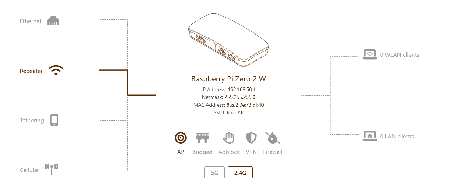
Created Raspberry Pi AP
We hosted the web-based user interface and GPIO control on the Raspberry Pi Zero 2 W for the machine. Our primary goal was to enable reliable access to the Pi’s web interface and file system in isolated environments, such as in the laboratory, without relying on a central Wi-Fi router, ideally through a mobile hotspot (without internet acces). Initially, we attempted to operate the Raspberry Pi as its own hotspot using the RaspAP software in “AP-STA mode.” This configuration was intended to allow the Pi to connect to a home network for internet access (therefore git pulls and easy version updates during development) while simultaneously broadcasting its own Wi-Fi hotspot, enabling devices like smartphones or laptops to connect and access the local web interface at 192.168.50.1. We installed RaspAP and configured the Wi-Fi client AP mode through the web interface, but we quickly ran into issues. The Pi Zero 2 W has only a single BCM43439 Wi-Fi chip, which became overwhelmed when tasked with acting as both a client and access point. Connections were frequently dropped because the connected devices detected no internet and failed the captive portal check. Although DHCP leases were assigned, web interface requests timed out endlessly, and both the lighttpd web server and DNS services crashed due to the load on the Wi-Fi driver. As a result, we decided to abandon RaspAP because the hardware of the Pi Zero 2 W was insufficient for this setup. To address these limitations, we offloaded the hotspot function to a dedicated microcontroller, using an ESP32-S3. The ESP32 created a Wi-Fi network named “Artista Amara,” and the Raspberry Pi acted solely as a client, connecting to this network. The ESP32 also hosted a small webpage at 192.168.4.1 that displayed all connected devices along with their IP and MAC addresses, making it easy to find the Pi’s IP. We flashed the ESP32 with an Arduino sketch using WiFi.softAP(). When moving the setup from home to the lab, we noticed extreme lag, with the web interface taking up to three minutes to load. Maybe due to interference from multiple Wi-Fi networks on the default channel 1. Additionally, repeated requests for cached resources from the PC browser caused the ESP32’s TCP/IP stack to stutter, producing 304 Not Modified errors. The Pi’s own Wi-Fi power management may also caused delays, as it would shut down the interface when idle. Due to time pressure we couldnt go further on that road and despite we thought that this should be a simple task it turned out to be massivly underrated. To achieve a fully stable and independent connection in the lab, we ultimately switched to a wired solution using USB OTG gadget mode. This allowed the Pi to connect directly to a MacBook or Windows PC via a USB cable, presenting itself as a virtual network card (Ethernet over USB) to the host computer. We prepared the SD card by modifying config.txt and cmdline.txt to enable the dwc2 overlay in peripheral mode and load the g_ether module.
This is definitely a point where we have to dig in again when working on the finalized version.
Nico: 0%
William: 100%
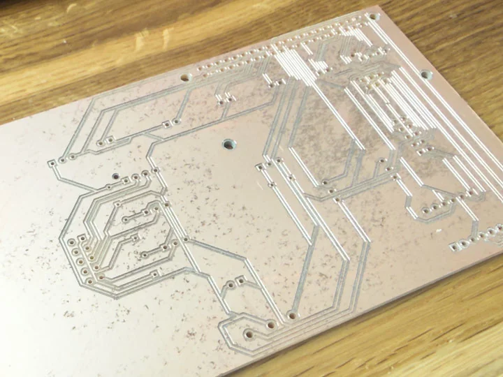
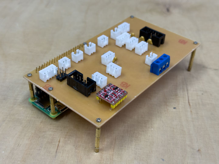
Designed, Milled and Soldered Pi HAT
We designed a custom Raspberry Pi HAT using Altium Designer to seamlessly integrate the Pi into the broader architecture of the latte-art machine. Acting as a compact, machine-specific interface board, the HAT replaced a chaotic web of loose jumper wires with a deliberate and robust hardware layer. It features dedicated 5V and 3.3V power distribution and provides structured, connector-based links between the Raspberry Pi, the ANET control board, relays, buttons, and various other pin-based control elements.
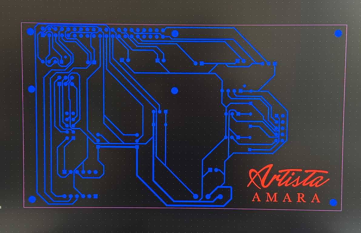
After completing the schematic and layout in Altium, we physically milled the PCB to bring the interface board to life. This milling process was crucial for achieving a clean, compact, and highly organized wiring structure tailored specifically to the machine’s geometry. Once the milling was complete, we soldered the necessary headers and components onto the board, allowing it to mount directly onto the Pi’s 40-pin GPIO header. Fully assembled, this custom HAT serves as a simplified, secondary mainboard for the Raspberry Pi side of the system, exposing reliable connectors for UART communication with the ANET J3 interface, relay logic, physical button inputs, and all additional machine control functions.
Nico: 0%
William: 100%
Electronics
Task group: Wire the power system
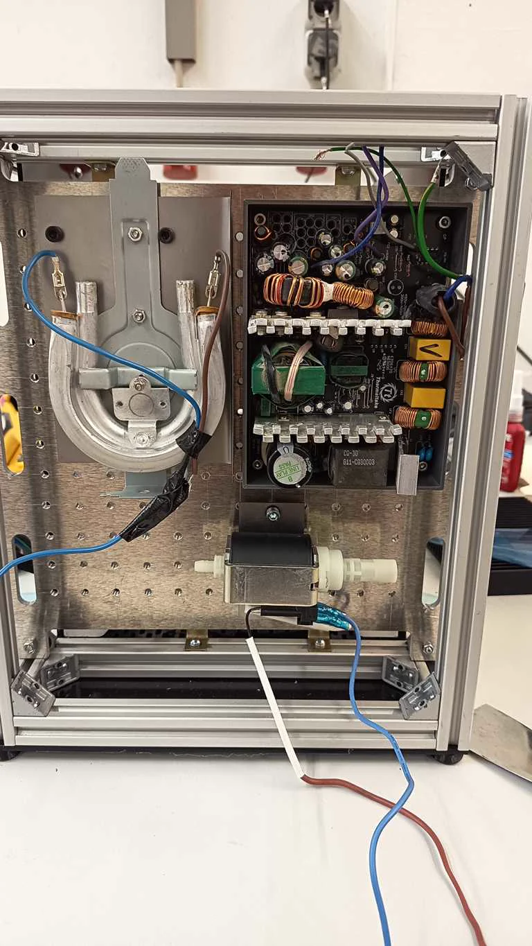
Wired 240V components
The 240 V components were mounted and wired on the rear area of the machine. This included power-related hardware, relay-related components, and milk-foaming elements that needed safer separation from the rest of the system. The rear panel helped keep the high-voltage section more organized and spatially separated from the motion and user-facing areas.
Nico: 100%
William: 0%
Grounded components
Grounding was part of making the power system safer and more deliberate. Because the machine combined mains-level components, metal parts, electronics, and fluid-handling hardware, grounding had to be considered as part of the full electrical structure. This supported safer operation during testing and later integration.
Nico: 20%
William: 80%
Installed Wago distributors
Wago distributors were installed to organize the power distribution inside the machine. They provided a cleaner way to distribute voltage levels and connect components than loose or temporary wiring. This step helped make the electrical system easier to inspect, extend, and maintain.
Nico: 100%
William: 0%
Wired voltage levels
The machine required several voltage levels, including mains voltage for higher-power components and lower voltage rails for logic, sensors, LEDs, relays, and the Raspberry Pi side. Wiring these voltage levels was part of creating a stable interface between power hardware, motion control, and machine logic. This work also connected to the Pi HAT’s 5 V and 3 V distribution role.
Nico: 70%
William: 30%
Crimped and prepared cables
To finalize the hardware integration, we meticulously crimped and prepared all custom cables, transitioning the machine’s wiring from fragile, temporary test connections to a robust and reliable final layout. Proper connector preparation was a critical step for seamlessly linking the motors, relays, power distribution network, physical buttons, sensors, and the custom Raspberry Pi HAT. For these connections, we primarily utilized JST connectors in various pin configurations, alongside ISP headers native to the ANET board’s layout. These ISP connectors proved especially handy for bundling multiple signal wires into a single, neat harness, making it straightforward to route cables cleanly throughout the machine. By establishing these secure, purpose-built connections, we ensured a much safer assembly process and drastically minimized the risk of intermittent faults or electrical failures during the overall integration of the system.
Nico: 10%
William: 90%
Integration
Task group: Integrate axes and wiring
Installed vee belt
The belt system was installed as part of bringing the motion platform together. Belts from the donor or adapted motion hardware were used to connect the motors to the moving axes. This step was necessary before the machine could perform coordinated motion tests.
Nico: 50%
William: 50%
Installed threaded rods
Threaded rods were installed as part of the axis hardware. They were reused or adapted from donor-machine components and had to match the new machine geometry. The threaded rods were important for stable motion and later needed alignment corrections because the spacing showed dimensional inaccuracies.
Nico: 50%
William: 50%
Installed bed rod
The bed rod was installed to support the cup bed and its movement within the machine. This step connected the mug bed work to the axis hardware. It helped bring the mechanical bed assembly into the same structure as the motors, belts, and threaded rods.
Nico: 50%
William: 50%
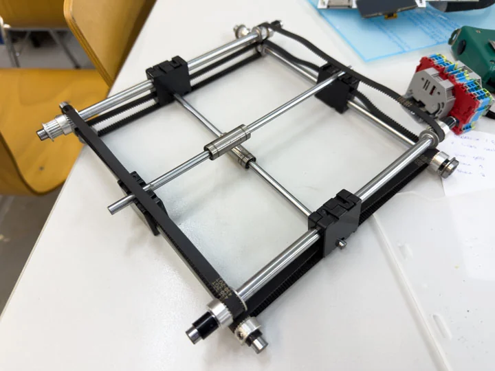
Printed alignment spacers
During assembly, we noticed inaccuracies of around 2 mm in width, especially around the rod spacing. Instead of remaking the entire assembly, we corrected this by printing alignment spacers and attaching them on all four sides of the rod system. This allowed us to compensate for the tolerance issue and continue with a more stable setup without loosing any performance.
Nico: 50%
William: 50%
Wired all axis and ran first 3-axis motion test
Once the timing belts, threaded rods, and bed-related rods were installed, all three axes were wired in a first provisional state. This wiring connected the mechanical axis setup to the ANET board and prepared the machine for coordinated movement. It was the bridge between the mechanical assembly and the first real motion milestone. The first three-axis motion test was an important milestone for the project. For the first time, the frame, mechanics, motor system, wiring, firmware, and ANET board came together as a functioning motion platform. This test showed that the adapted machine structure could move in a coordinated way and validated a major part of the overall build.
Nico: 50%
William: 50%
Print test with milk
For the first print test with milk, we used a simple circular movement for the axis control. We set the radius slightly smaller than the radius of the cup, so the movement stayed inside the usable area.
Before the circular movement starts, the Z-axis moves first. This raises the coffee cup towards the nozzle and brings the milk surface into the correct working distance. After the printing process, the cup is lowered again to create enough clearance.
The movement itself is relative to the start position. First, the head moves from the center point to the edge of the circle. From there, it follows the circular path while dispensing milk foam. This allowed us to test the basic combination of cup positioning, axis movement, and foam output with a real medium instead of only dry motion tests.
The result was not perfect yet. We were not able to fully optimize the foam settings at this stage, so the visible print quality is still moderate. The interaction between air injection, suction, temperature, and milk flow needs more work to generate a stable and fine foam structure. Especially the foam consistency has a strong influence on whether the printed shape stays visible on the surface.
Even though the result does not look perfect yet, it is already very useful for a first prototype. The machine was able to move along the defined circular path and dispense milk foam during the movement. This confirmed that the mechanical and control concept works in principle.
Here is a short video of the test:
The unusual noises in the video come from the old 3D printer motors we used for the prototype.
Nico: 50%
William: 50%
Final Reflection
Overall, we hope that this documentation shows the real scale of the project. Many smaller tasks are not even listed here, because otherwise the documentation would have become too large and difficult to follow.
During the project, we faced significantly more problems than expected. In the last two days, two Raspberry Pis failed, and we even had to pick up a third one on Tuesday evening. Because of this, the final phase became extremely time-critical. Some tasks could not be completed exactly as planned, and we had to keep adapting our plans until the very last moment to still finish with an acceptable result.
Even though the machine-building process was very intense, we both enjoyed it a lot. We worked on it almost continuously and the workload was definitely stressful at times, but in the end we turned our vision into reality. That alone made the effort worth it.