Coherent Laser
Group members
Preparing the Machine
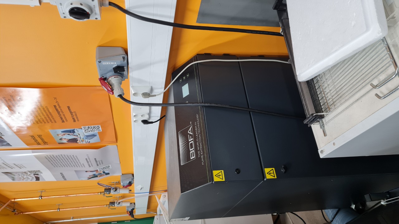
Turn on the fume extractor
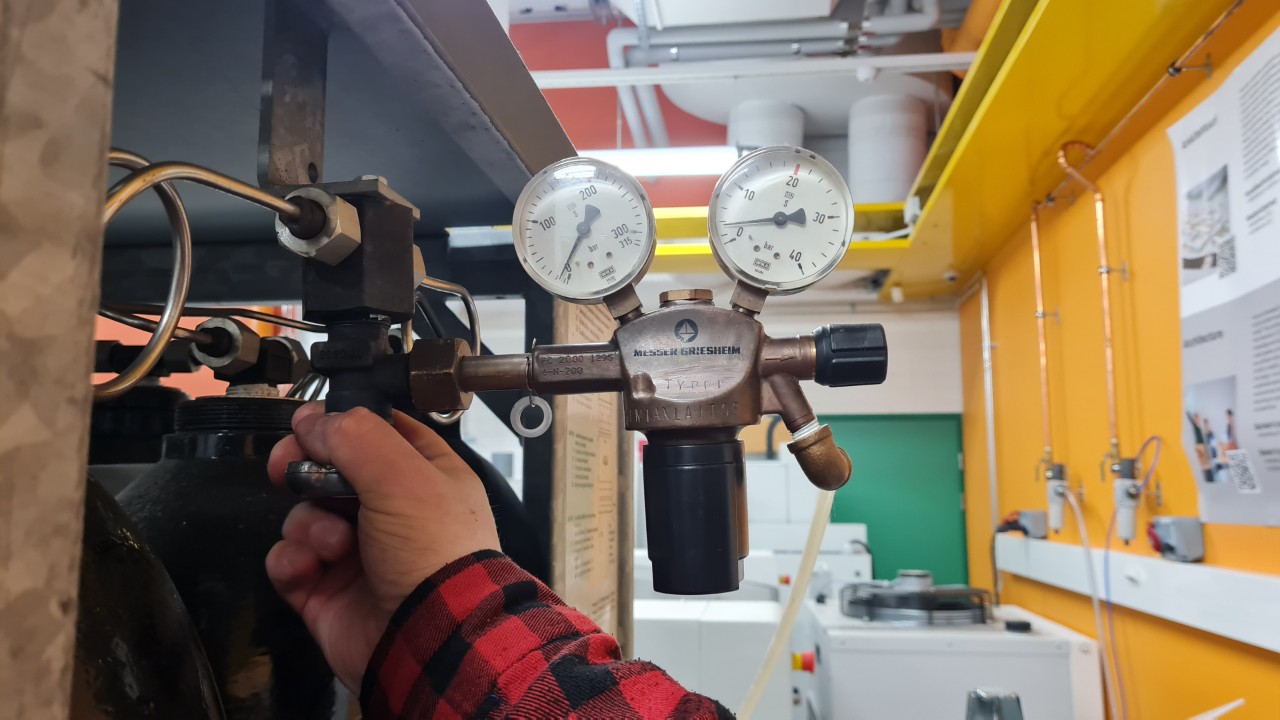
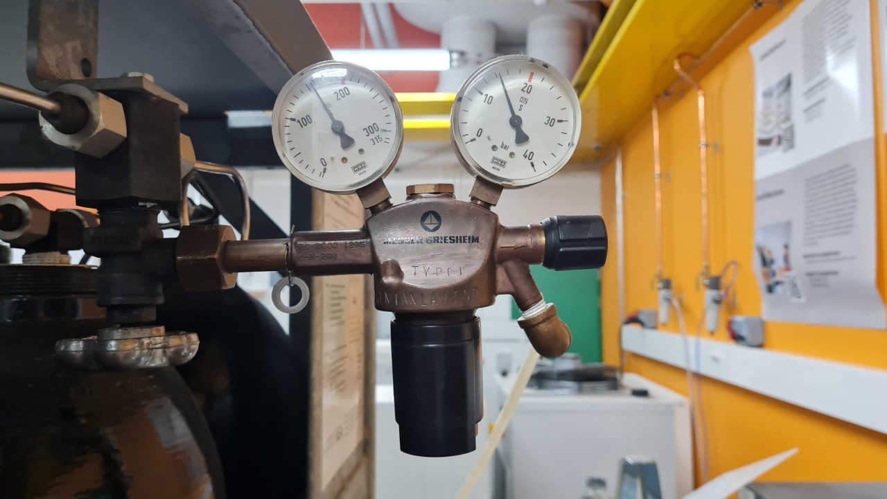
Open the nitrogen tank valve
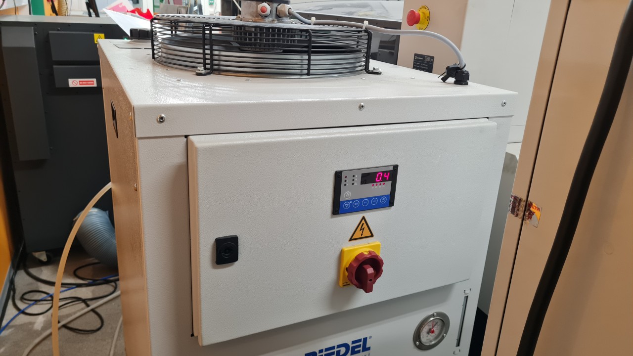
Turn on the water cooling unit
Release the emergency stop button and turn on the laser
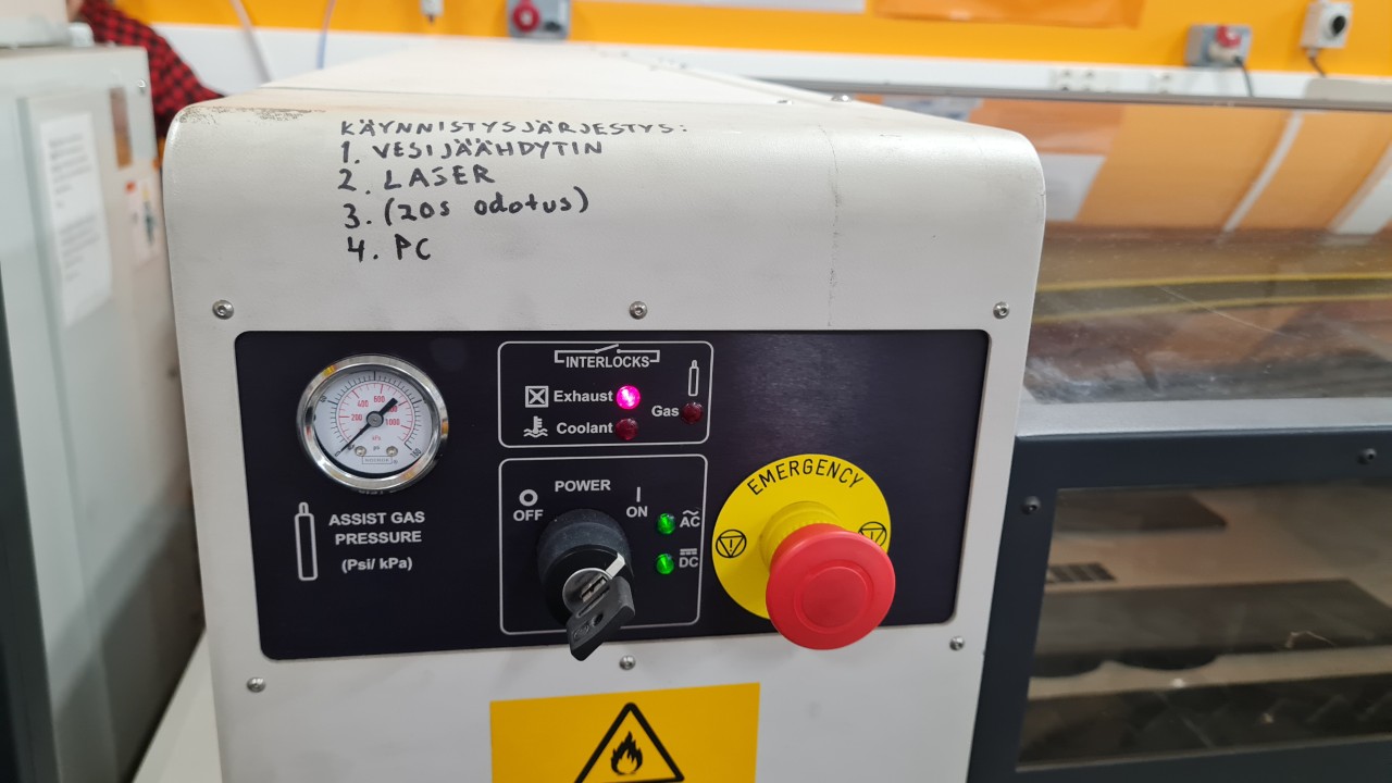
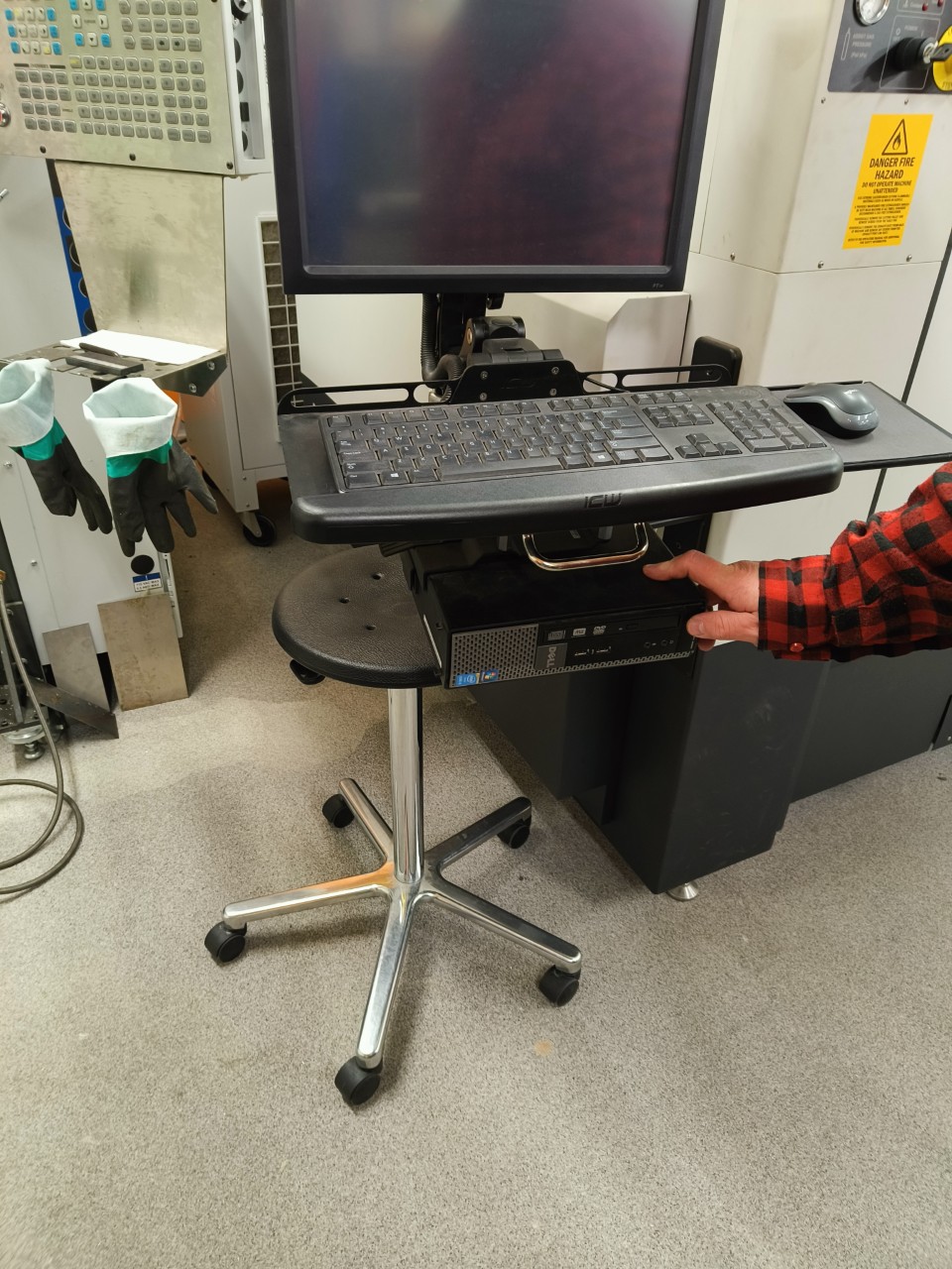
Turn on the laser PC
You need to wait for the laser to fully turn on before turning the PC on. Recommended time is 20 s.
Preparing the G-Code from a DXF File
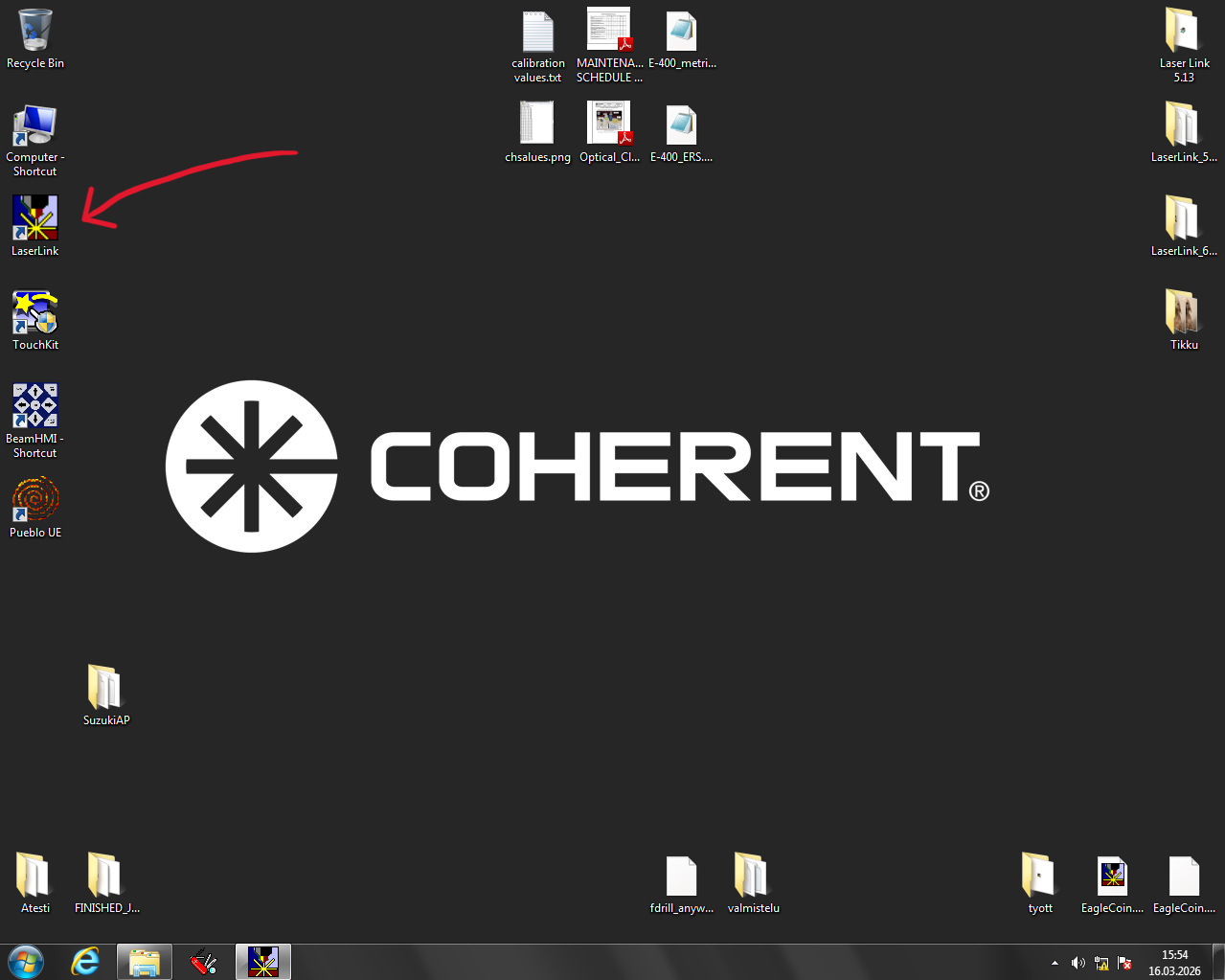
Open Laser Link
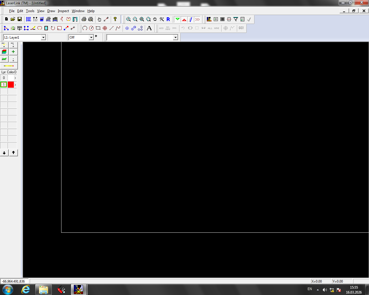
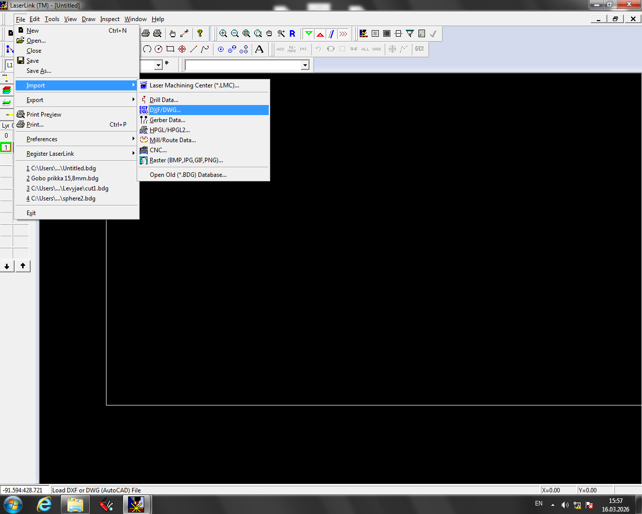
Import the DXF file
From the top menu select File >> Import >> DXF/DWG...
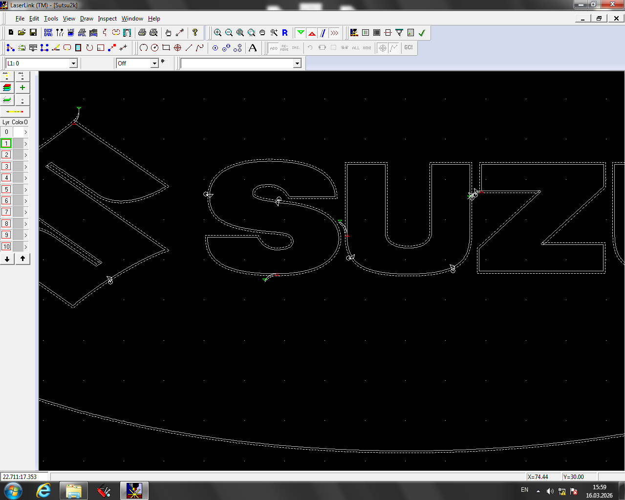
Move the design to the bottom-left corner of the design area
To move an object:
- Press the Move button.
- Draw a selection area around the object, or left-click the lines you want to move.
- Confirm the selection by pressing the right mouse button.
- Left-click the starting point, then click the destination.
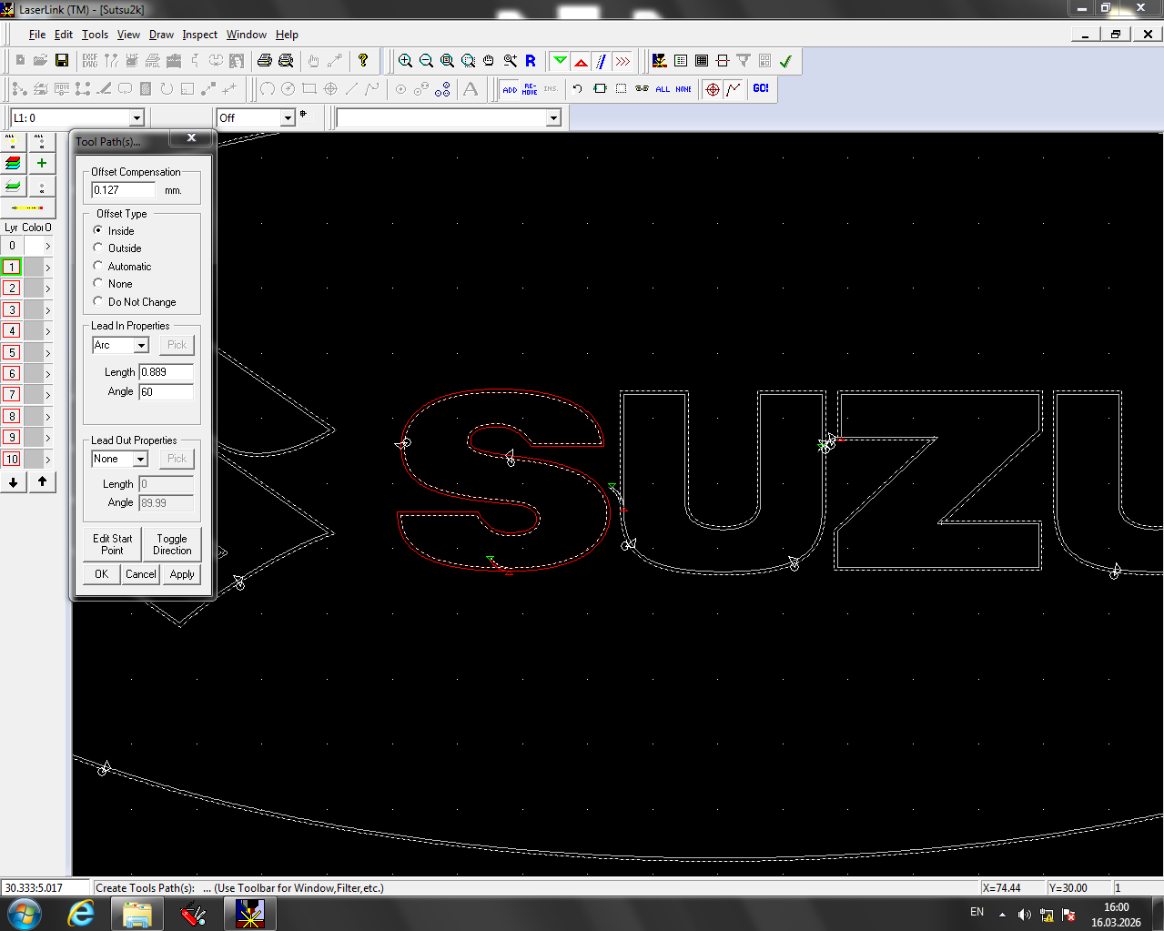
Adjust cutting paths
After import, all vector lines default to Cut with the cut position set outside the line. In this step, set whether to cut Inside, Outside, or On the line.
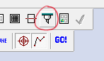
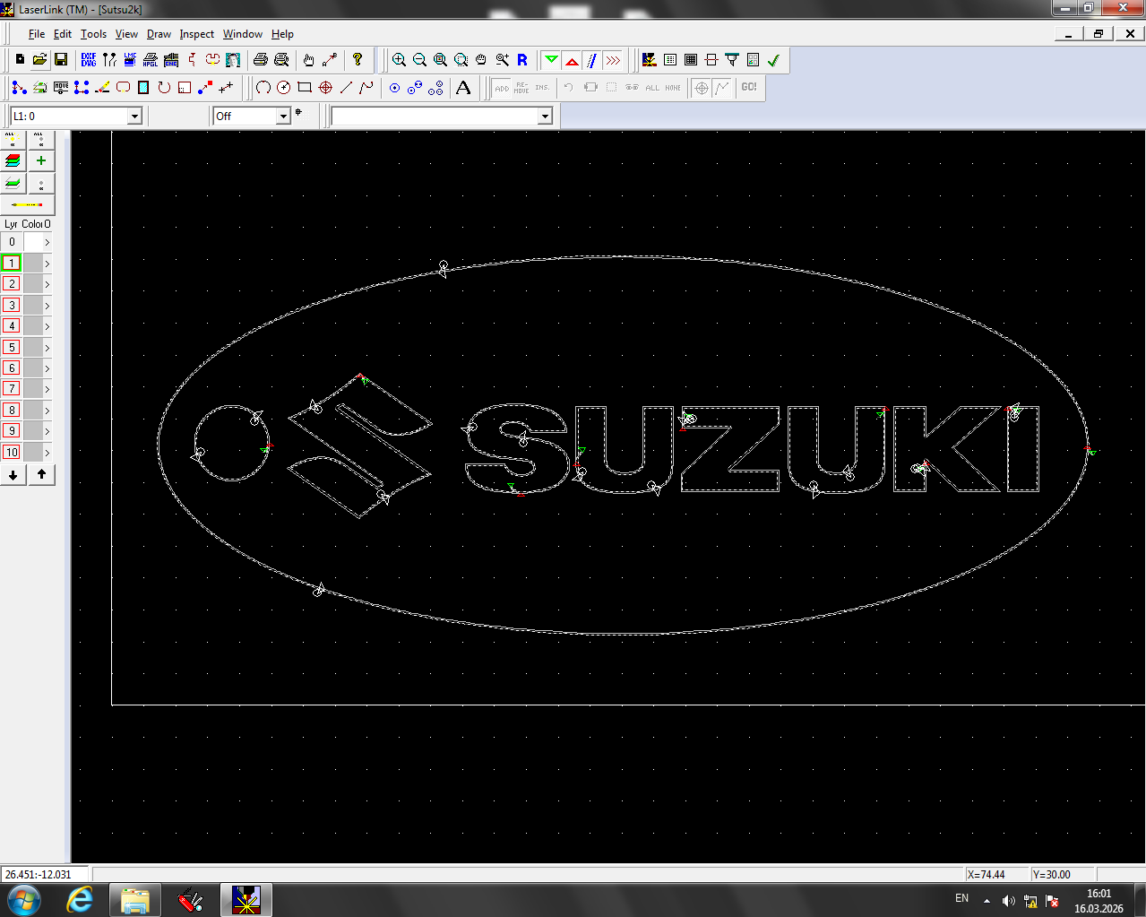
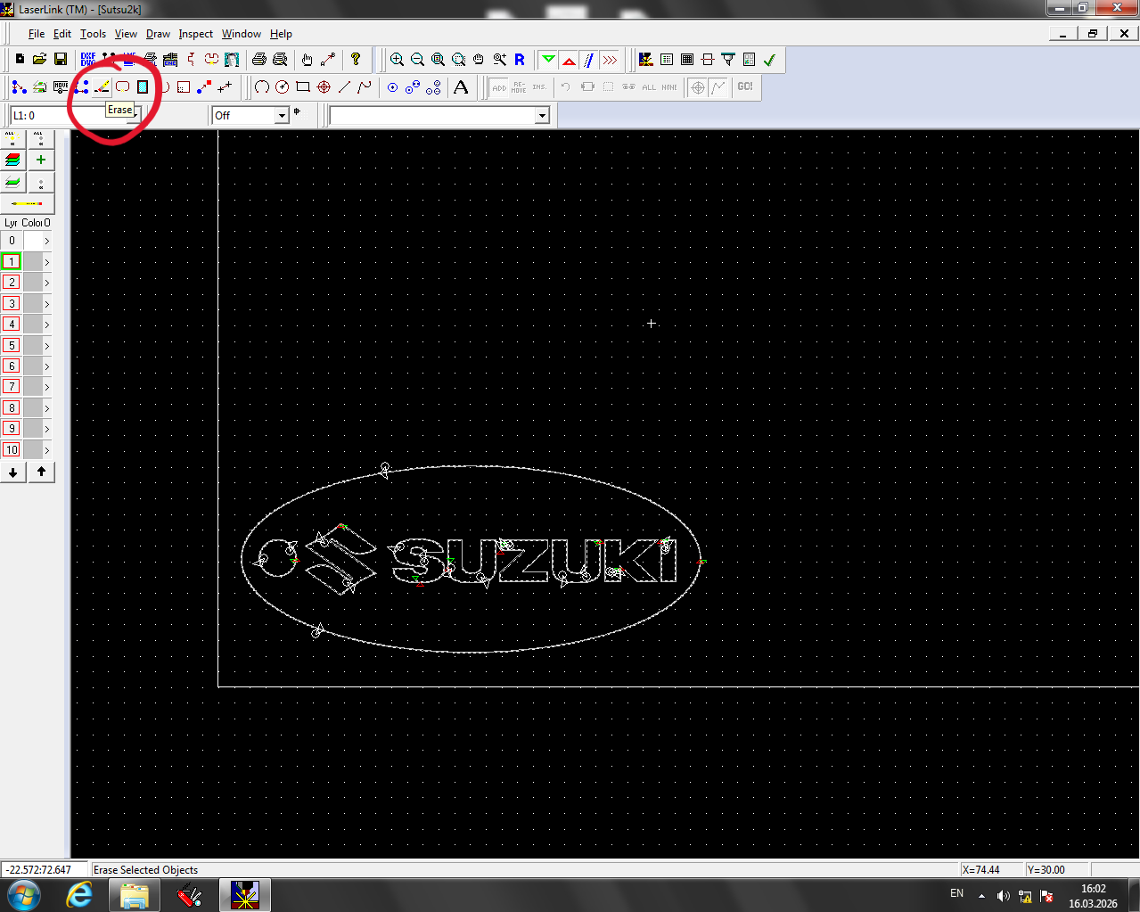
To remove paths that should not be cut, use the Erase tool:
- Activate the tool.
- Draw a selection area or left-click to select paths.
- Confirm with right-click.
Set the cutting order
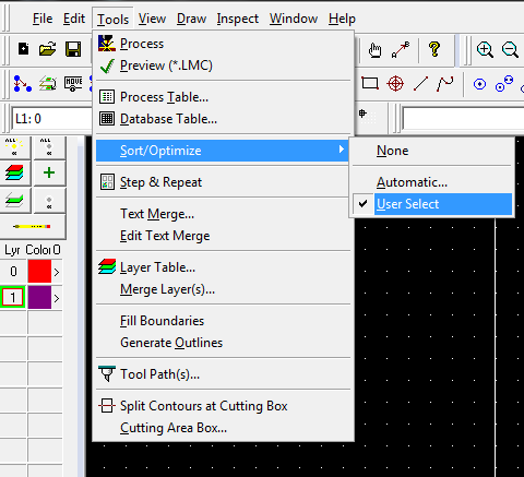
The order of cuts matters — inner features should be cut before outer contours so parts do not shift.
To set the cutting order:
- Go to Tools >> Set/Optimize >> User Set.
- Click paths in the desired cutting order (first clicked = first cut).
- Confirm with right-click.
Set the process table
Select the Process Table tool.
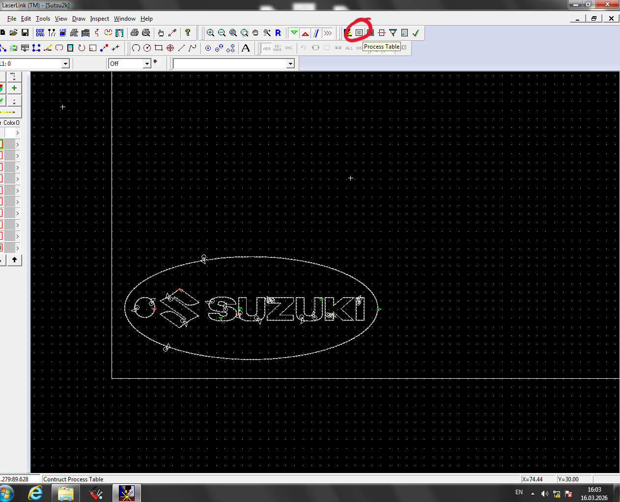
Double-click the layer containing your design.
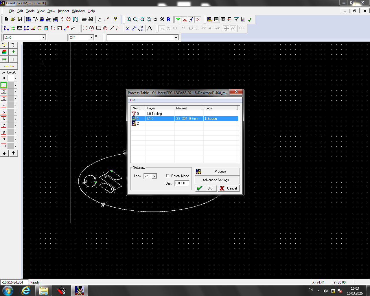
We were cutting 1 mm stainless steel. Select the closest matching material preset — in this case
SS_304_0.9mm_cut.
Settings recommended by Auno
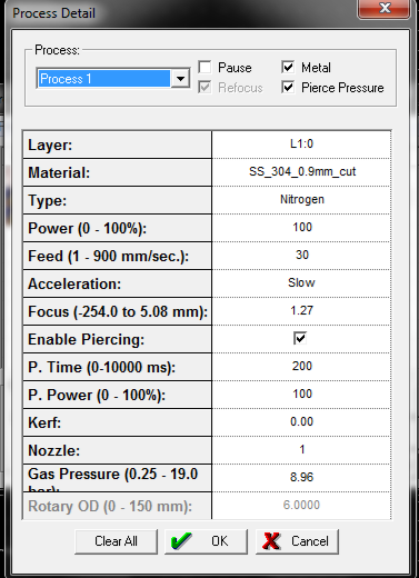
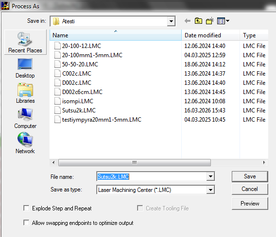
Press Ok to save the settings, then press the Process button in the Process Table window. Save the generated .LMC file to a known location (e.g. ~\Desktop\Ateesti\).
Laser Cutting
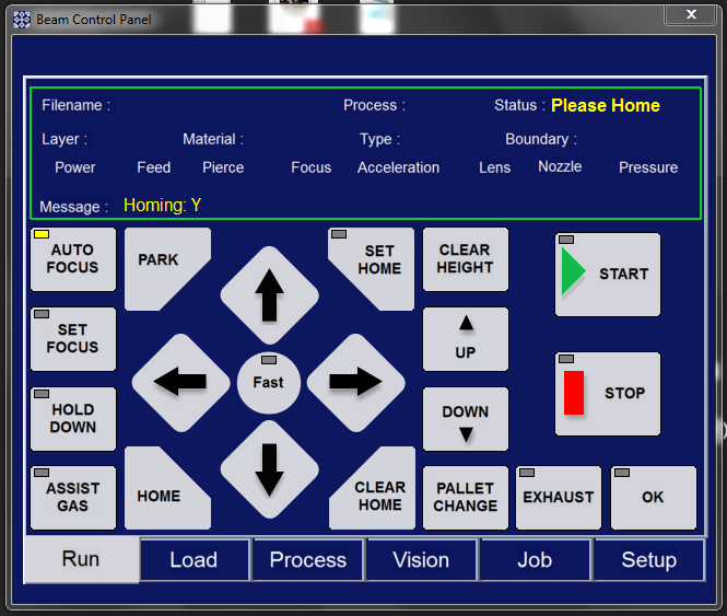
Open Beam Control Panel and bring the laser head to the front
Place the material and ensure it is flat
Use metal stock pieces to hold the material down and keep it flat.
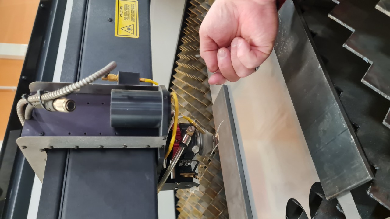
Bring the laser head over a flat, hole-free section of the material and set a temporary home
Position the head near (but not over) the cutting area. There is a red pointer to help with placement.
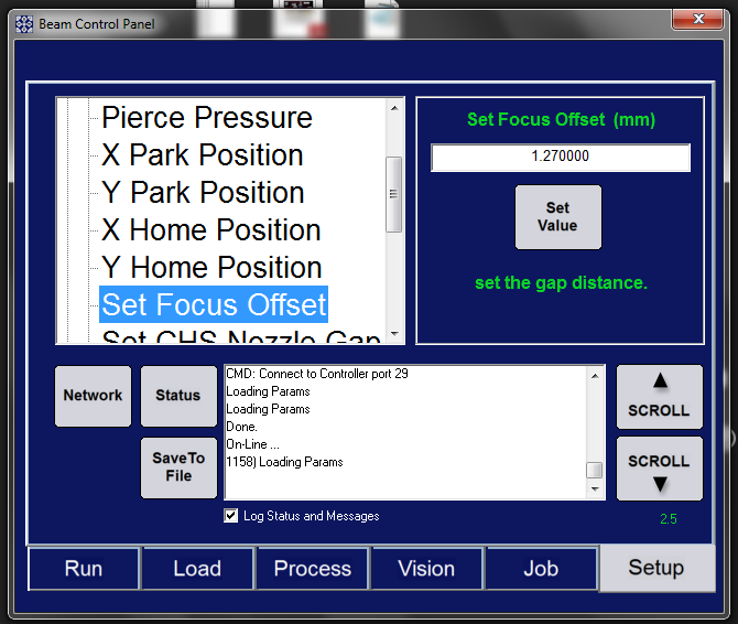
Enter the focus offset value
Using the on-screen buttons (not the physical keyboard), enter the same focus height value used in the Process Table. Auno recommended 1.27 for 1 mm stainless steel.
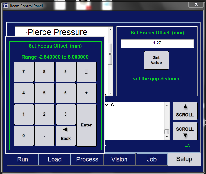
Click Set Value
The laser will eject the probe and automatically measure the material surface, then move roughly 1.5" above it.
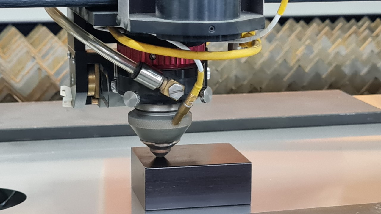
Set the physical focus height with the spacing block
Take the 1.5" spacing block and place it under the laser head. Adjust the laser height using the red ring until the spacing block fits snugly between the laser head and the material.
Calibrate the lens (beam centering)
This must be done before every cutting operation. The laser head is held by magnets and can shift when the laser is powered off.
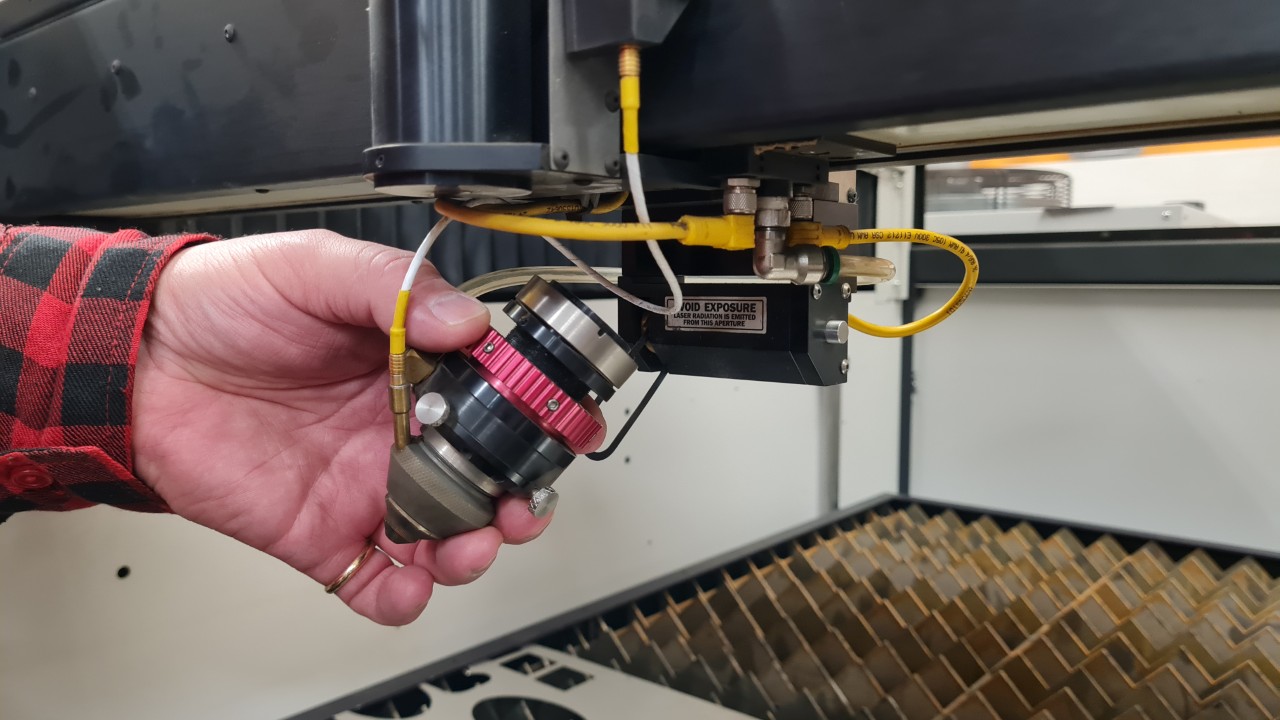
To calibrate the lens:
- Place a small patch of tape over the laser nozzle tip.
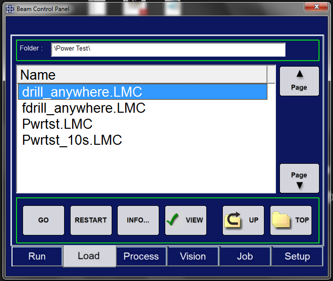
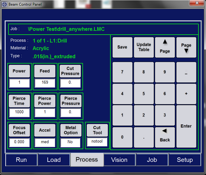
- Open
drill_anywhere.LMC.- First run: disable Auto Focus and run the job once. This releases pressure from the gas-assist line — running with tape on this first pass will blow the tape off.
- Place a fresh piece of Scotch tape on the nozzle tip.
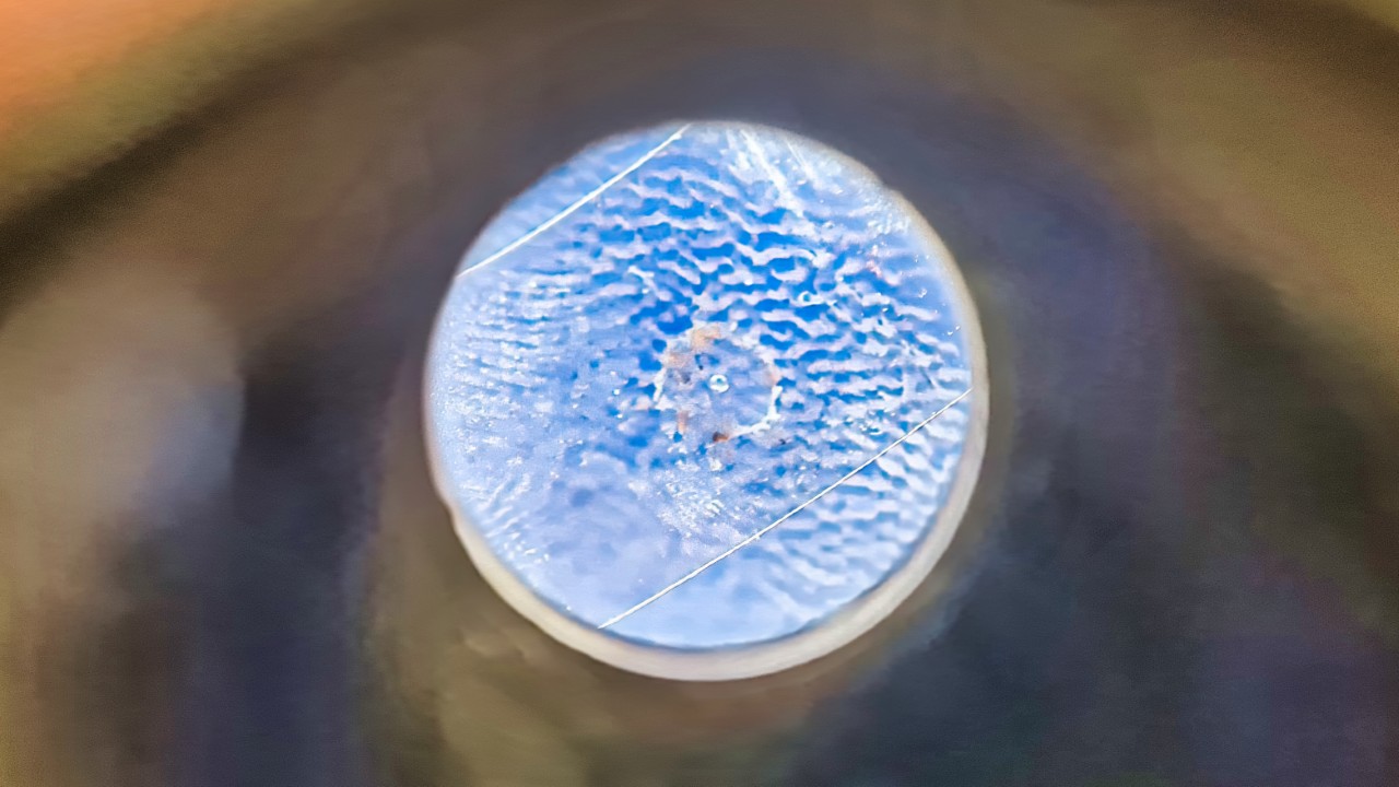
- Second run: run the job again. Wait for the Exhaust indicator to turn off, then open the laser and inspect the tape.
- The tip of the nozzle will leave a circular impression on the tape. The hole burned by the laser should be exactly centered within that circle. If it is off-center, use the 3 adjustment screws on the laser head to shift the beam and repeat until centered.
Set the origin
Position the origin at the bottom-left corner of your design on the material. Leave enough margin on all sides so the laser head does not collide with the metal stock used to hold the material down.
Select your file and verify settings
Always use the on-screen buttons to set values — do not use the physical keyboard buttons. To confirm that values are applied, switch between tabs and check that the values persist.
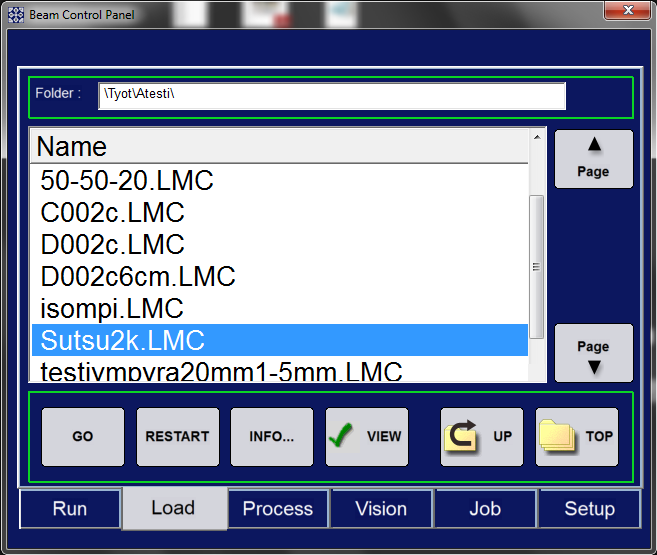
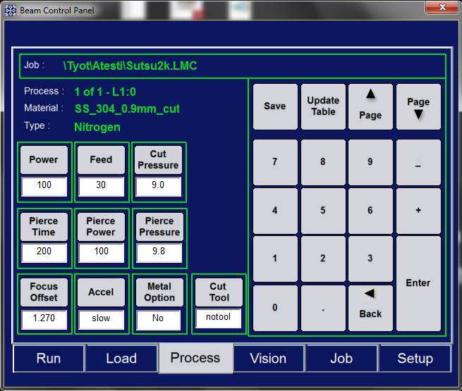
Press Start
Monitor the cut. Wait for the process to finish and collect your part only after the Exhaust light turns off.
Retrieve parts that fell through the grid
If parts fall through the metal grid to the bottom of the laser, go to Setup >> Clear-out Height >> Clear. This lowers the laser table and releases the bottom drawer.
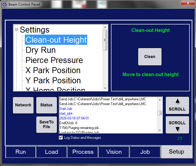
Bottom drawer release
Push the drawer all the way back until it falls over the small ledge at the end of the track. If the drawer is left ajar, the laser will report an error that it is open.
Shutdown
Turn off the following in order:
- Press
Parkbutton to move the laser head to the back of the laser - Cooling unit
- Fume exhaust
- Close the nitrogen valve (the pressure will slowly go down)
- Laser computer
- Laser
- Press the emergency stop button