3. Computer Aided design
The objective of this week is to Evaluate and select 2D and 3D software then Demonstrate and describe processes used in modelling with 2D and 3D software.
2D Software
Inkscape
Inkscape is an open-source vector graphics editor like Adobe Illustrator. To download the software, visit the inksace website or windows store.
One of the software benefits that it allows you to redraw the images with bad resolution. I start by downloading a cat picture and open it by Inkscape (File<<open). The next step is to change the picture opacity by selecting the uploaded image << Objects << Fill and stroke, a small window will show up and you can control the opacity I select it to be 50%. The final step is to select the Bezier Tool and start drawing be moving around the outline of the original photo.
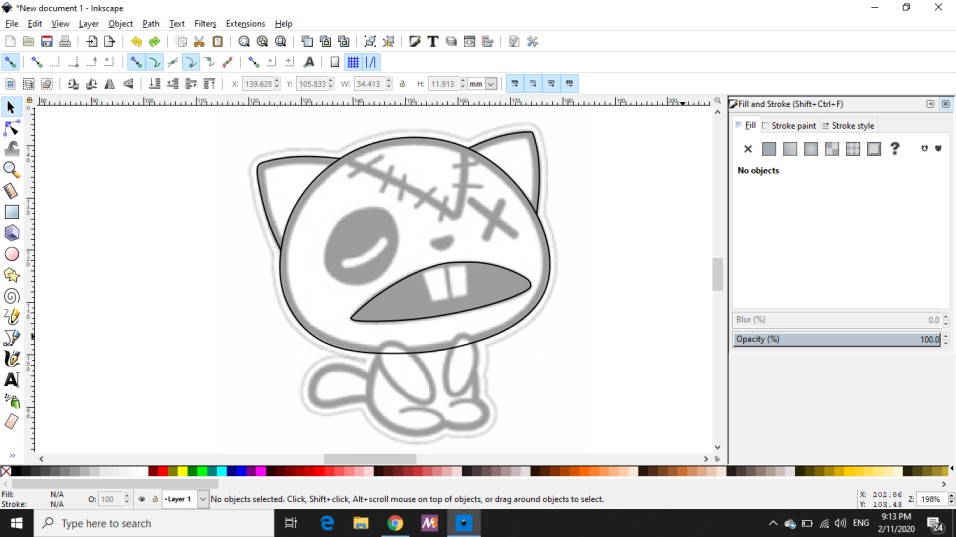
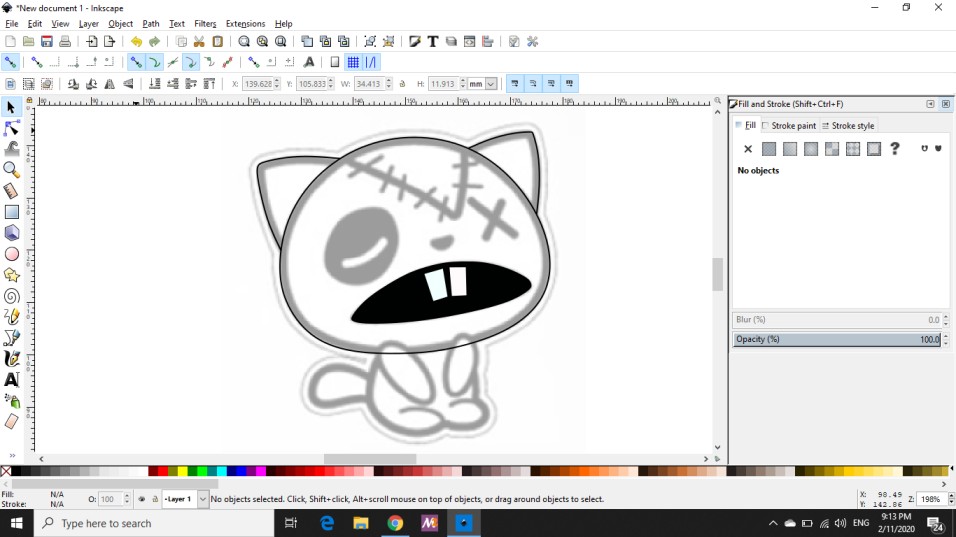
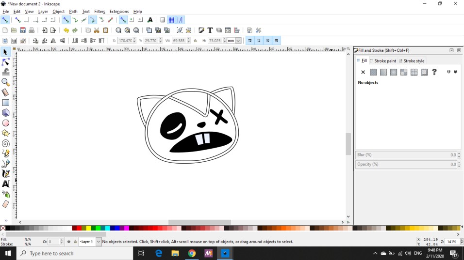
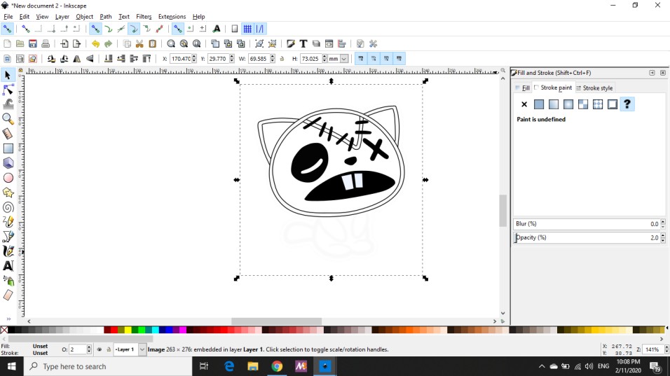
The final resoult is shown below

GIMP
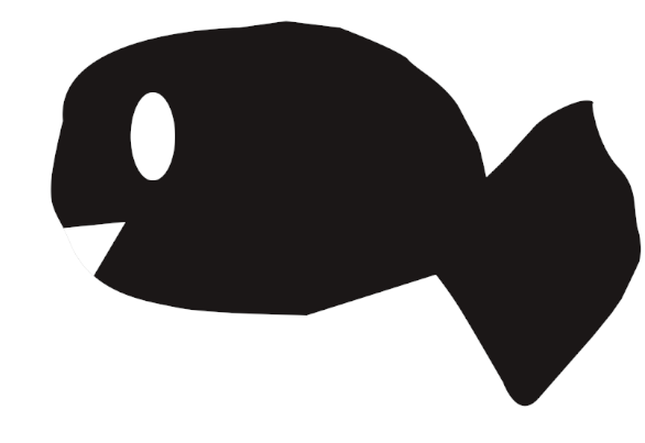
GIMP is free and Open Source Image it is available for windows, Linux and OS X. It seems to be a little bit difficult at first but once I understand the function of the important it become much easier. While I am investigating the software, I drew the following picture:
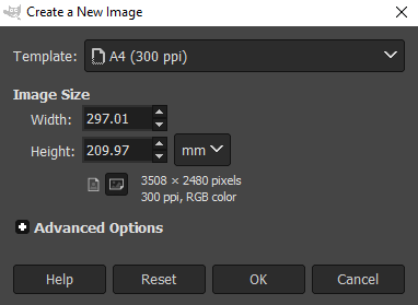
To do this I first go to File << New, the following window will be shown to select the size of the new image for my image I selected to be landscape A4.
Then I select the paths tool to draw the curves as shown below
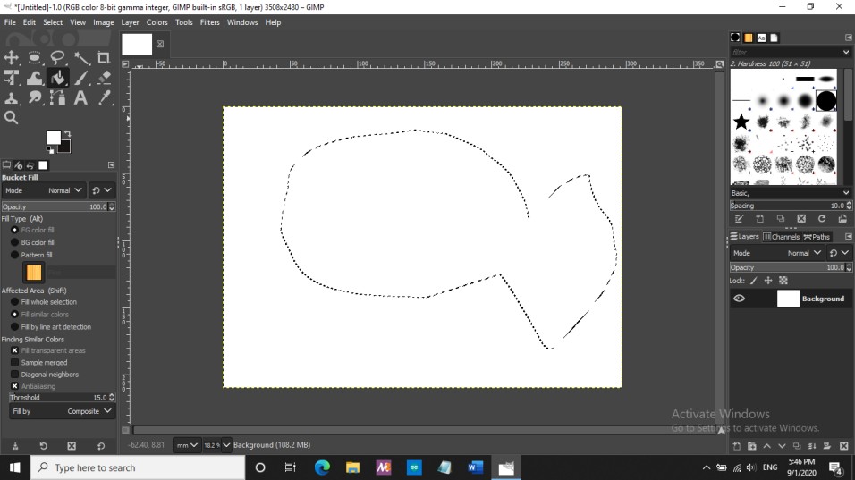
After that I select the bucket fill tool to fill the fish shape with black color then from my keyboard I type the litter ‘e’ to draw the circle and color it with bucket fill tool the which is the eyes then I reuse the paths tool to make the mouth.
3D Software
FreeCAD
FreeCAD is an open source 3D modeler made primarily to design any objects of any size. Once FreeCAD is opened the following window will show up.
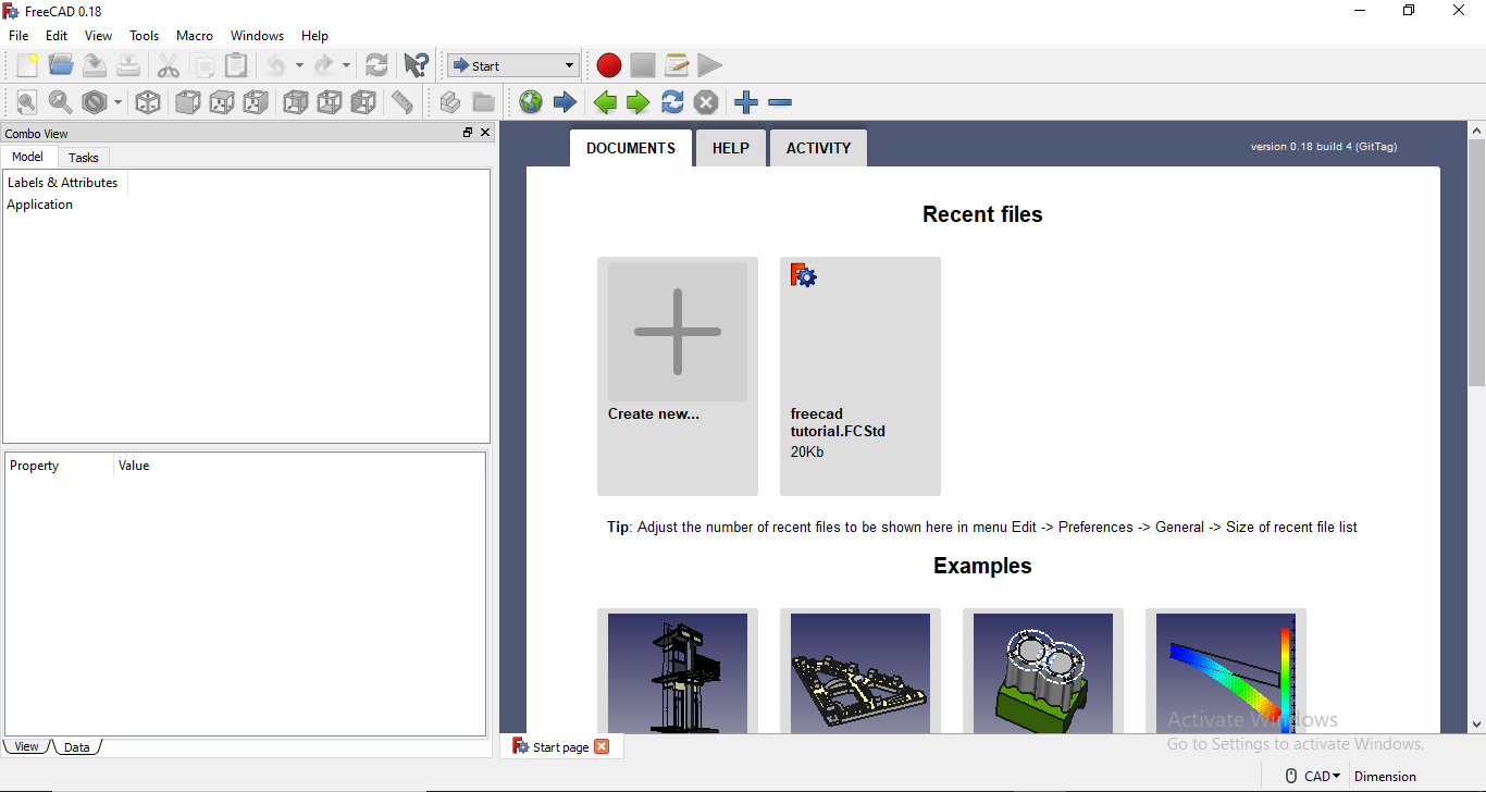
I start by clicking on ‘Create new’ and start to see the software environment. Then I tried to do random shape by drawing a cube so to do that go to view << workbench << part, then click on the icon with the cube shape.
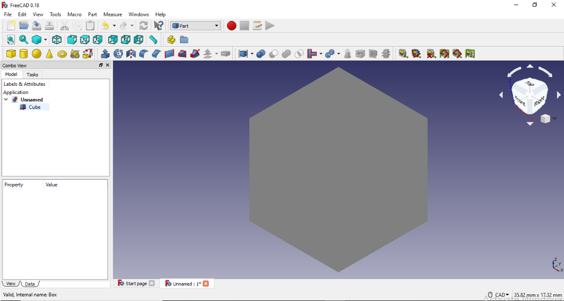
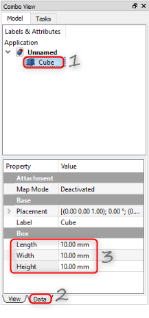
After that I change the dimension of the cube to 90 mm by doing the steps in the picture below
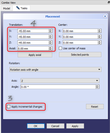
Then I insert another cube and change both the dimension to 80mm and I change the placement by following the steps in the picture
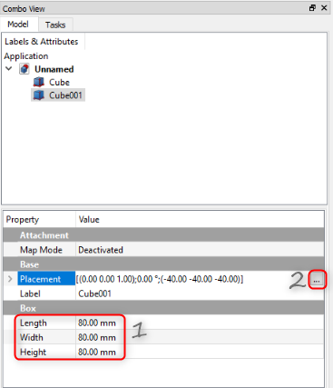
it is important to check the apply incerment changes before changing the object postion
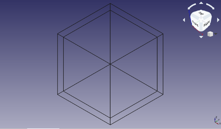
The result of all the previous steps is shown below
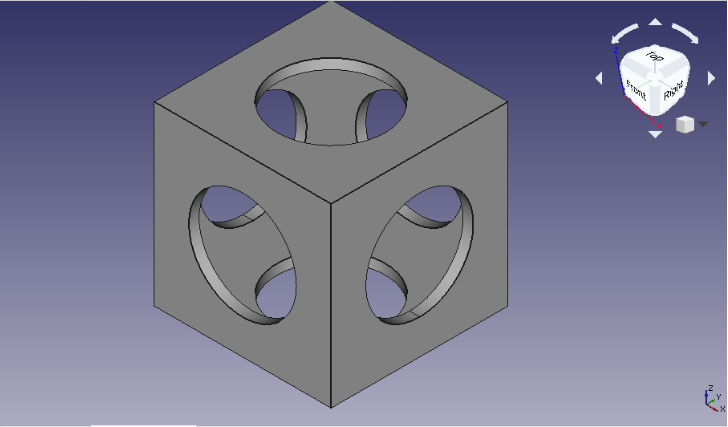
Finally I insert to cylinders and change the dimention and the placement of both of them and rotate one of them by dowing the same stepes above. The final result is shown in the figuer below
Fusion 360
Fusion 360 is a cloud-based 3D CAD platform for product development. It combines industrial and mechanical design. The tools in Fusion 360 enable fast and easy exploration of design ideas with an integrated concept to production toolset.
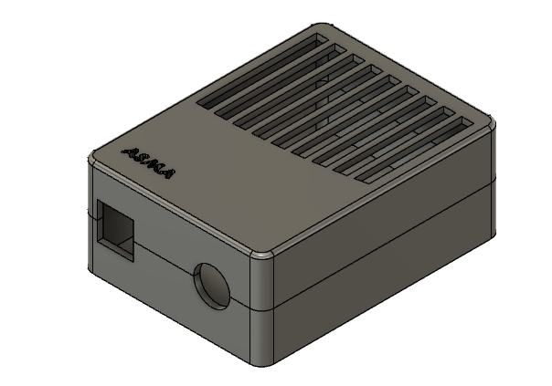
In fusion 360 I decided to design an Arduino case, so I follow the step below 1. Create a new sketch, select the plane you want to draw on and Draw a square and close the sketch. 2. Go to solid and select the extrude tool, click on the square and select the required hight. 3. To soft the edges go to solid << modify << fillet and select the desired edges 4. To evacuate the solid box, go to solid << modify << Shell. 5. To separate the box into two, create a new plane by going to solid << construct the go to Modify << split body. 6. To draw the side square and circular go to sketch and select the front face and draw both of them then extrude both of them through the evacuated box. 7. To write your name start a new sketch, select the top surface and then select text and write you name once you finish, extrude it again. 8. To add some design again start a new sketch and draw the design that you want and extruded if you want.
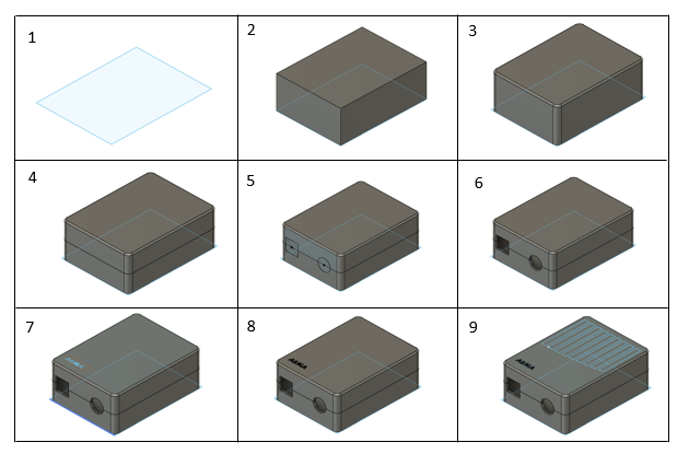
The final result is shown in the picture below