Final Project
This week I worked on defining my final project idea and started to getting used to the documentation process.
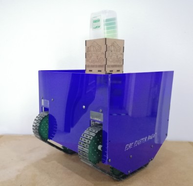
The Final machine pictures and video
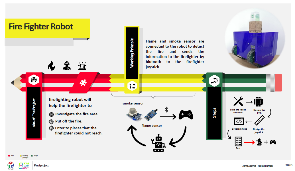
Concept
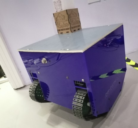
Fire spreads rapidly if it is not controlled. So, in order to overcome this issue, safe firefighter lives my final project is an autonomous firefighting robot. It will help the firefighter to investigate the fire area before they enter to it, put off the fire and enter to places that the firefighter could not reach and send feedback.
Structure and Building
BOM
- Fire (flame) Sensor
- Smoke sensor
- Switch
- Wires
- PCB
- Water pump
- DC motors
- Spray Tube
- Relay
- Battrey
Bsae of the robot
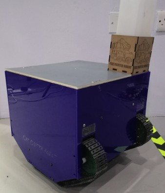
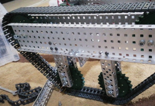
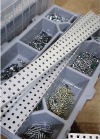
In this project I used a mechanical kit in order to build the Structure of the robot. I decided to make it looks like a tank so I used a chain and stroke as a wheel with 4 servo motor to drive them.
Bsae Cover
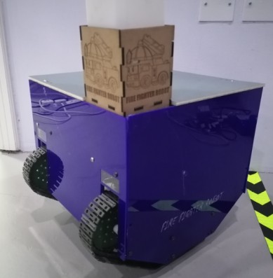
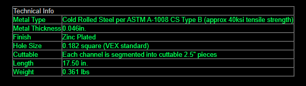
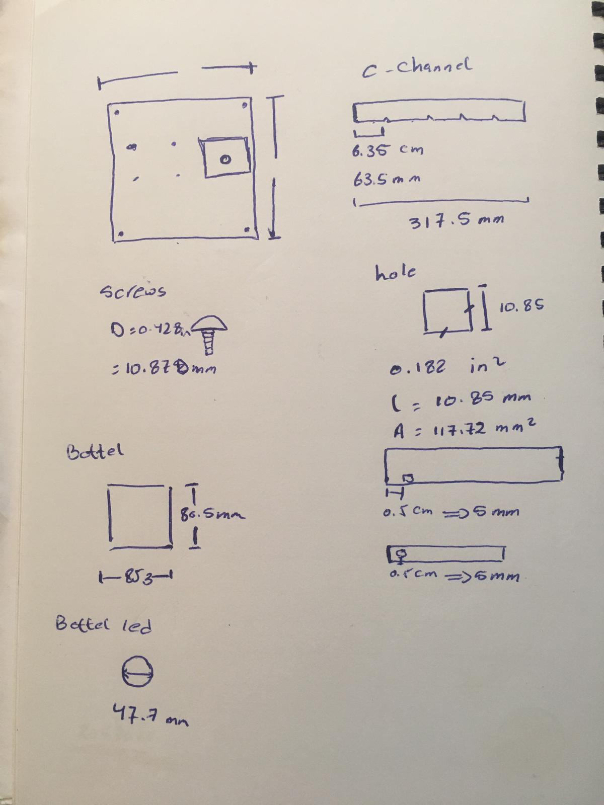
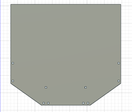
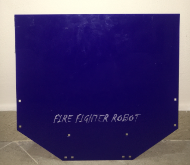
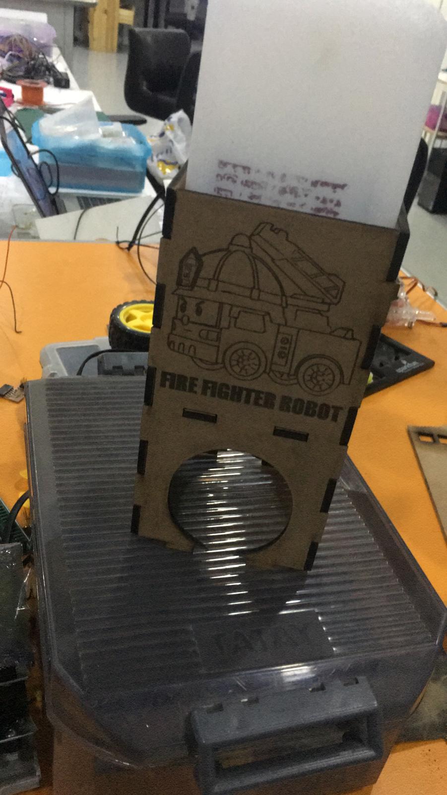
In order to design a cover for the robot body I go to search for the specification of the machinal kit and take the measurement from the data sheet and do some calculation. Knowing the specification allowed me to make a holes in my cover exactly at the same place in the kit in order to attach them together easily by screws and nuts. As the Base cover will be a little bit big so I decided to use an acrylic sheet and cut it by the laser machine and for decoration a use the scan property in the laser machine to write “Fire fighter robot” keep in mind to mirror what ever you design to be scanned for the machine to draw it correctly.
measurement of the machinal kit.
Right and left cover
Front cover
Back cover
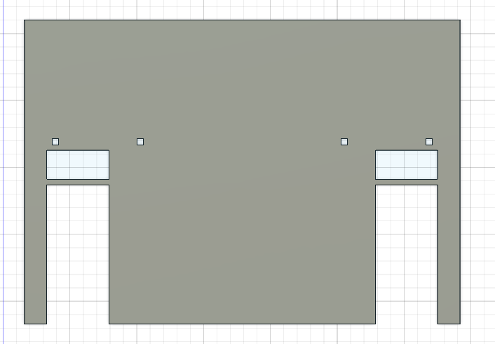
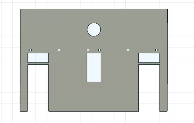
Front cover
To cover up all the electircal component I design a top cover and cut it with laser machien
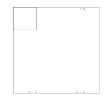
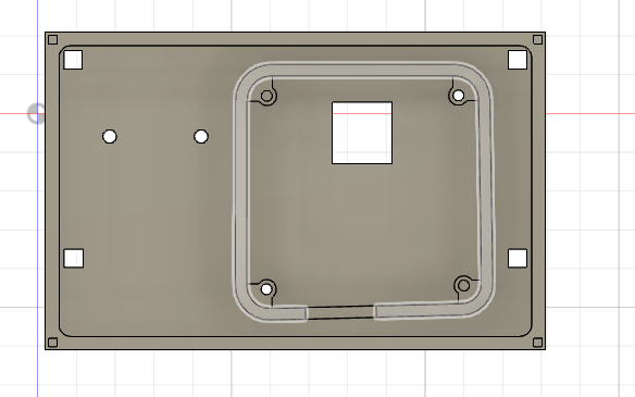
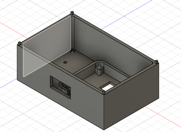
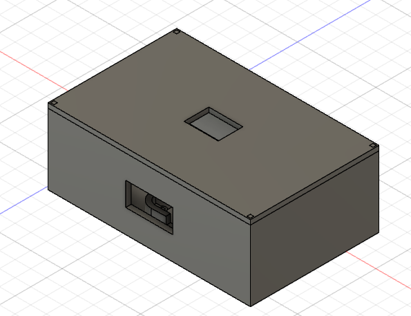
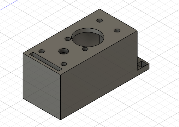
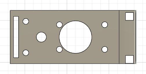
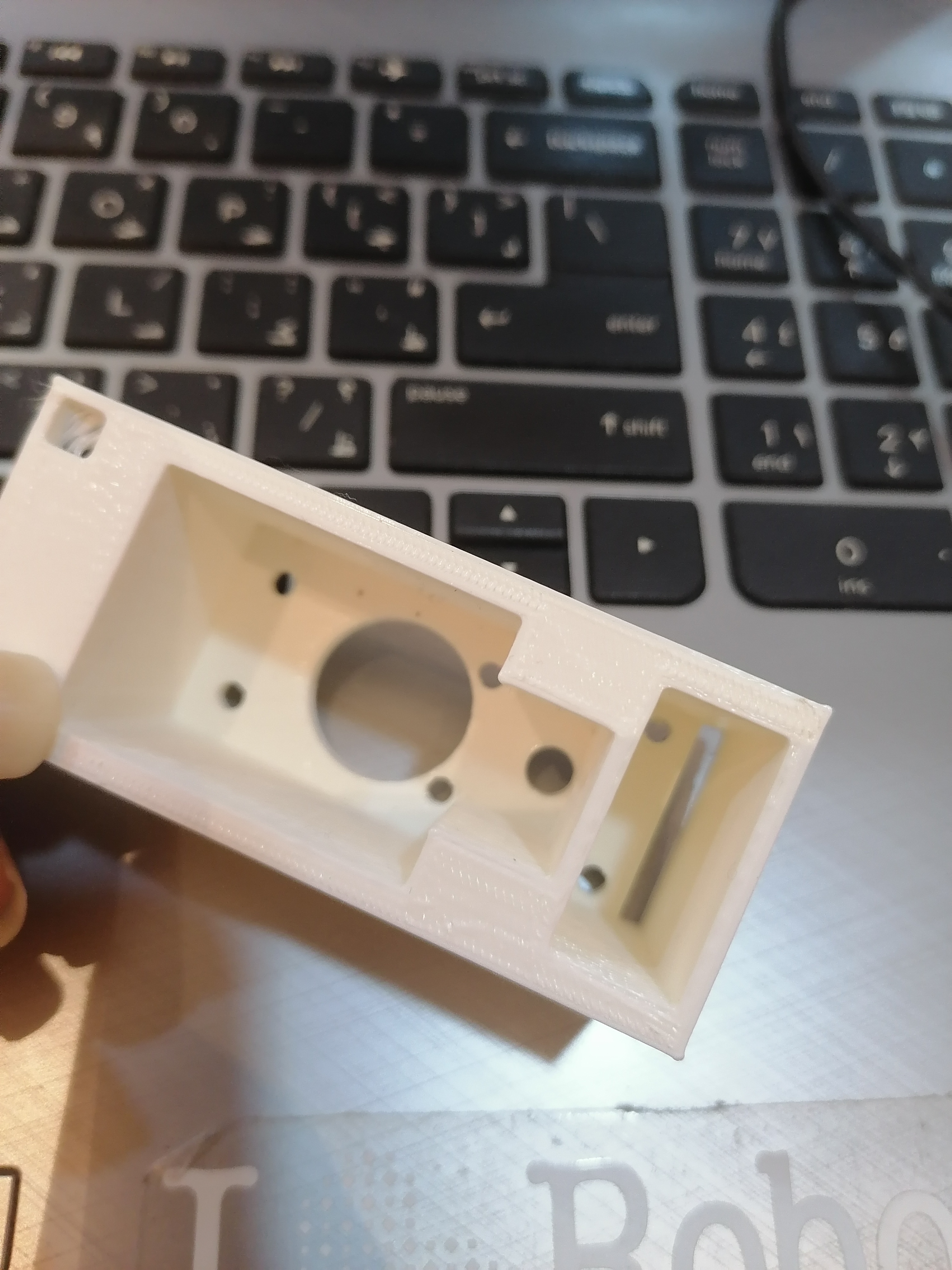
Electronics Box
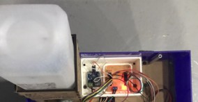
In order to keep the PCB and the relay and wires away of the water tank I design and 3D print a electronic box by tacking in consideration the measurement of my circuit and the relay. There is a small square in front in order to allow the wires to be connected to the PCB
Flame, Smoke and Bluetooth cover
To place the sensor in front of the of the robot a box or a cover should be made to place them so I decided to design and 3D print a cover by considering the measurement of each sensor.
Bottele cover
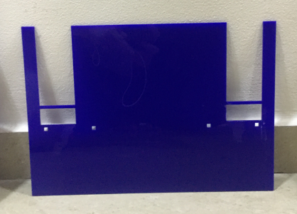
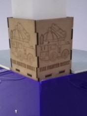
In order to keep the water tank or the water bottle directly above the pump I bottle holder must be designed. By taking the measurement of my bottle I decided to make cuboid shape and cut it with the laser machine taking in consideration that I will attach them together without using any screws. For decoration I used a photo from the internet in order to draw it in the sides of the bottle holder.
To make the water tank stable I stick the cover wall with the base cover to ensuer that the cover, the botter and the pump will not vabriate if the robot move.
Electronics
PCB Design
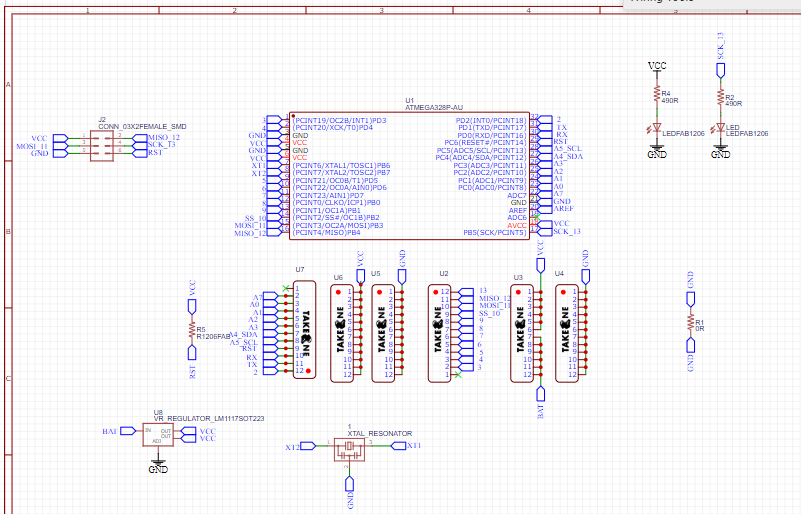
In this week I designed a circuit that I will use in my final project. Since I will use many inputs and outputs, I chose to go with Atmega328p as it has many input and output pins. I started the design by trying a new software which is EsayEDA, I found it much easier than Eagle. So, to start the design I follow the following steps:
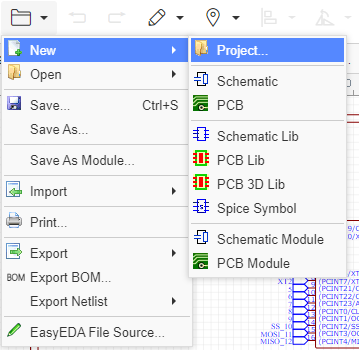
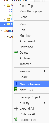
- Open EasyEDA >> File >> new project, select a name for the project then highlight the project << Right click<< new schematic.
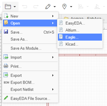
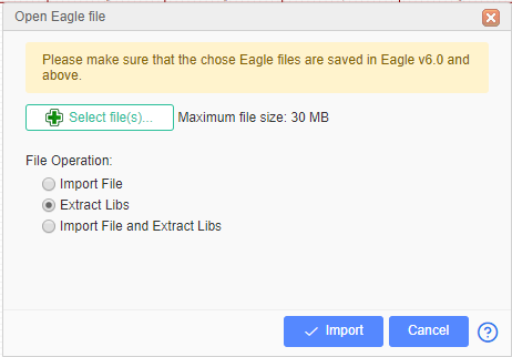
- Go to file >> import >> Eagle >> select files to browse to the fab library and select extract Libs >> Import >> Check all the boxes next to the symbol and click the “Add to My Library” button.
-
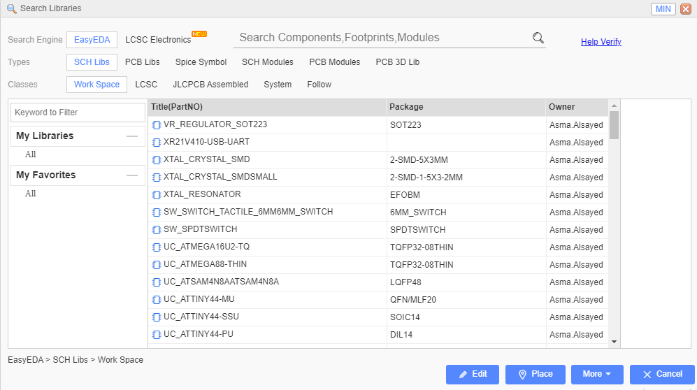
Click OK after successful import.
-
Insert all the component by clicking on the library icon and search for them.

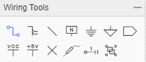
- Connect the component together by using the wire from the wiring tools.
The final result of the schematic design.
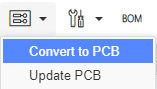
- Go to convert icon << convert to PCB.
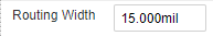
- Arrange the wires so their will be no intersection between them but make sure that the width routing is 15 mil.
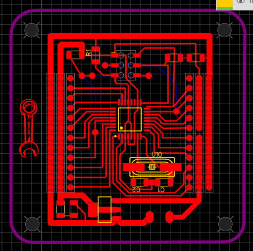
- Go to file >> export >> SVG >> select the red layer >> and export.
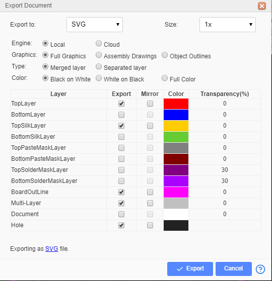
-
Repeat step 8 to export the outline and the holes.
-
Open the file in Mods and select the proper setting as in week7 to generate the rml file.
-
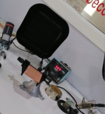
Open the rml file with SRM-20 milling machine software, adjust your origin and the mailing bit.
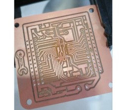
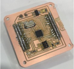
- Solder the circuit components
The final result
-
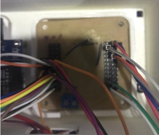
Test The circuit by connecting the PCB ISP with the Arduino pins by the following configuration:
-
Arduino GND connects to Pin 6 (GND)
-
Arduino Pin 13 connects to Pin 3 (SCK)
-
Arduino Pin 12 connects to Pin 1 (MISO)
-
Arduino Pin 11 connects to Pin 4 (MOSI)
-
Arduino Pin 10 connects to Pin 5 (Slave Reset)

- Upload a small blinking code by using the arduino as a programmer to make sure that the circuit is working properly
void setup() {
  pinMode(LED_BUILTIN, OUTPUT);
}

void loop() {
  digitalWrite(LED_BUILTIN, HIGH);
  delay(1000);
  digitalWrite(LED_BUILTIN, LOW);
  delay(1000);
}
Input device
Flame sensor
Flame sensor is types of sensors are used for short range fire detection and can be used to monitor projects or as a safety precaution to cut devices off / on. The configuration pin of HC-SR04 is VCC, TRIG , ECHO, and GND. The supply voltage of VCC is +5V and you can attach TRIG and ECHO pin to any Digital I/O in your Arduino Board. I Connect the VCC and GND pins to the 5V and GND in the PCB , then I connect digitl output pin of the sensor to pin 9.
The results is shown in the video
Smoke sensor
MQ2 gas sensor is an electronic sensor used for sensing the concentration of gases in the air such as LPG, propane, methane, hydrogen, alcohol, smoke and carbon monoxide. MQ2 gas sensor is also known as chemiresistor. It contains a sensing material whose resistance changes when it comes in contact with the gas. This change in the value of resistance is used for the detection of gas. I Connect the VCC and GND pins to the 5V and GND in the PCB , then I connect analog output pin of the sensor to pin A7.
Output device
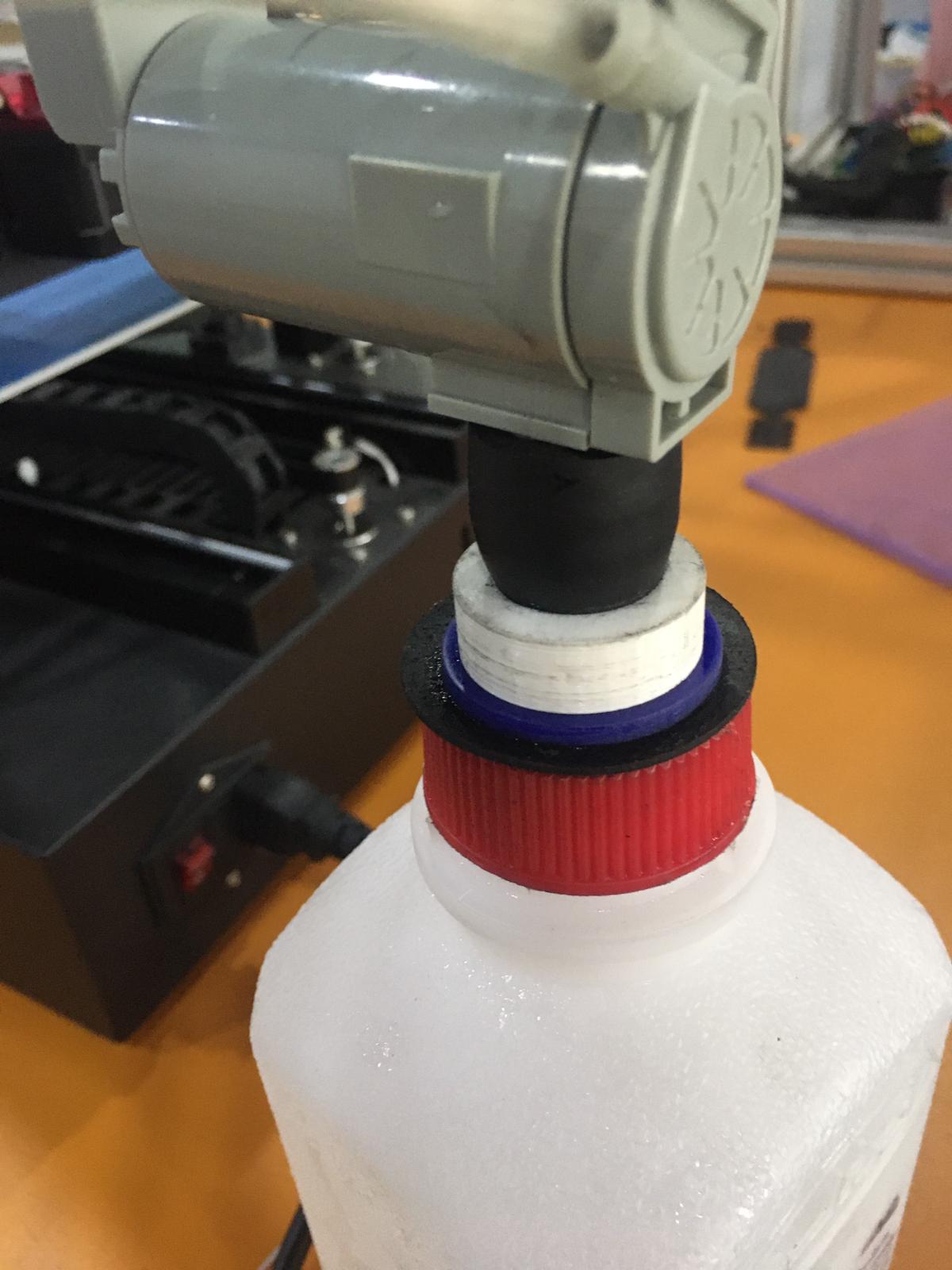
Water Pump
In this project I used a windshield washer pump which is designed to suck windshield washer fluid from the reservoir, through the supply lines, to the spray nozzles and onto your windshield. By the same Working principle I decided to use it as normal water pump to release water when the flame sensor indicate a flame or a fire. I connect the water pump to a relay and connect the relay to pin 8 in my PCB and supply the pump with 9V.
Servo motor
2-wire Motor 393 is a 2-Wire Motor, it build rotational mechanisms, drive bases, rotational joints, conveyor belts - anything that spins can be built using the 2-wire Motor 393. In my design I used 4 motor with 4 motor controller. and I connect them to my PCB in Pin 6 and 5 for the left side motors and pin 4 and 3 to the right side motors. It is important to consider which been you attach the motor with in order to make the motor in each side work in the same direction.
#include <Servo.h>

Servo leftfront;
Servo leftback;
Servo rightfront;
Servo rightback;
Servo wheel;

#define stop_motor  1500
#define forward     2000
#define backward    1000

void setup()
{
  leftfront.attach (8);
  leftback.attach (9);
  rightfront.attach (10);
  rightback.attach (11);


  // Left / Right
  move(stop_motor, stop_motor);

}

void loop()
{
  move(stop_motor, stop_motor);
  delay(2000);
  move(forward, forward);
  delay(8000);
  move(backward, backward);
  delay(2000);
  move(backward, forward);
  delay(2000);
  move(stop_motor, stop_motor);
  delay(8000);
}

void move(unsigned int leftSide, unsigned int rightSide) {
  leftfront.write(leftSide);
  leftback.write (leftSide);
  rightfront.write (rightSide);
  rightback.write (rightSide);
}
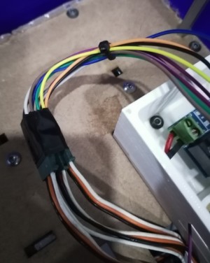
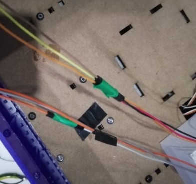
wiring
It is important to wireup the component in proper way to avoid any shotage in the circuit and to ensure that every component git the needed current. In order to taht I use a Cable tie and cable tape.
Embedded programming
To embed the program to my PCB I use the Arduino UNO as ISP and upload the code that I get from compiling the code that I have made input week, output week, networking and communication and interface and application. However, some modification in the code have been done in order to fit the function of the robot.
#include  <Relay.h>
#include  <Servo.h>
#include  <ArduinoJson.h>

DynamicJsonDocument   JSON(150);

#define   PumpPin         8
#define   FireDetector    9
#define   SmokeSensor     A7

#define   stop_motor  1500
#define   forward     2000
#define   backward    1000

Servo leftfront;
Servo leftback;
Servo rightfront;
Servo rightback;

Relay pump(PumpPin, false);

unsigned int leftPrev   = 0;
unsigned int rightPrev  = 0;
bool  smoke_informed    = false;
bool  fire_informed     = false;

void setup()
{
  // Communications Port
  Serial.begin(9600);

  // For Pump Function
  pump.begin();
  pump.turnOff();

  // Connecting Motors To Pins
  leftfront.attach(5);
  leftback.attach(6);
  rightfront.attach(3);
  rightback.attach(4);

  // Left / Right
  move(stop_motor, stop_motor);
}

void loop()
{
  // Command For Moving
  if(Serial.available()) {
    String msg = Serial.readStringUntil('\n');
    while(Serial.available()) Serial.read();
    msg.trim();

    // Making Sure Document Is Clear
    JSON.clear();

    // Deserialize the JSON document
    DeserializationError error = deserializeJson(JSON, msg);

    // If Error Do Nothing
    if (error) {
      JSON.clear();
    } else {
      // Reding JSON Values
      unsigned int leftM  = JSON["LM"];
      unsigned int rightM = JSON["RM"];
      unsigned int pumpC   = JSON["PM"];

      // Moving The Motors
      move(leftM, rightM);

      // Controlling The Pump
      if(pumpC == 1) {
        pump.turnOn();
      } else {
        pump.turnOff();
      }
    }
  }

  // Fire Detector
  fireDetector();

  // Smoke Detector
  smokeDetector();
}

void move(unsigned int leftSide, unsigned int rightSide) {
  // Left Side Movment
  if(leftPrev != leftSide) {
    leftfront.write(leftSide);
    leftback.write(leftSide);
    leftPrev = leftSide;
  }

  // Right Side Movment
  if(rightPrev != rightSide) {
    rightfront.write(rightSide);
    rightback.write(rightSide);
    rightPrev = rightSide;
  }
}

bool fireDetector() {
  if(digitalRead(FireDetector) == LOW && fire_informed == false) {
    Serial.println("FR");
    pump.turnOn();
    fire_informed = true;
  } else if(digitalRead(FireDetector) == HIGH && fire_informed == true) {
    Serial.println("NFR");
    pump.turnOff();
    fire_informed = false;
  }

  // Return Boolian Value
  return fire_informed;
}

bool smokeDetector() {
  if(readAnalogSensor(SmokeSensor, 10, 0) >= 70 && smoke_informed == false) {
    Serial.println("SM");
    smoke_informed = true;
    return smoke_informed;
  } else if(readAnalogSensor(SmokeSensor, 10, 0) <= 65 && smoke_informed == true) {
    Serial.println("NSM");
    smoke_informed = false;
    return smoke_informed;
  }
}

double readAnalogSensor(uint8_t pin, uint8_t times, uint8_t delays) {
  double temp = 0;

  for(int i=0; i<times; i++) {
    temp += analogRead(SmokeSensor);
    delay(delays);
  }

  temp/= times;

  return temp;
}
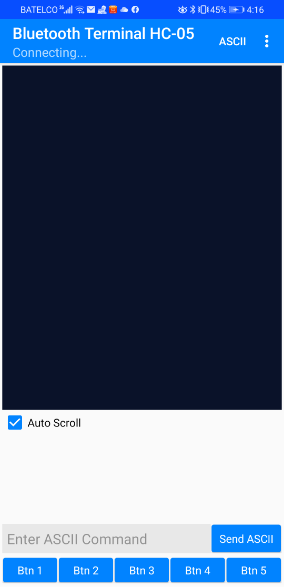
User interface
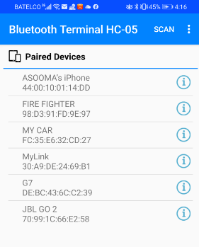
To make the user able to control the robot I used an application called “Bluetooth Terminal HC-05”, The application allow me to set a number off button to do the needed function and also receive the signal from the sensor to tell me the state of it. I used a HC-05 and named as firefighter, once you open the app it shows you all available Bluetooth devices and you select the desired one.

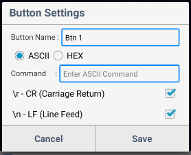
In order to program the buttons the following code must be written in the command section {“LM”:”1500”,”RM”:”1500”,”PM”:”0”} ; LM to store the value of the left motor, RM to store the value of the right motor and PM is the pump state ON or OFF.
-
To Move Forward
-
To Move backward
-
Stop