This week's assignment is to add an output device to a designed micro-controller board and program it to do something (individual); to measure the power consumption of an output device (in-group).
* All C++ and KiCad files can be downloaded here.
* This week's group assignment is to measure the power consumption of an output device.
* My plan for this week's progress was to make and/or test basic actuators in order to understand how they work and to design a board with built-in actuators. The board will be fabricated after the lockdown.
Characterizing output devices
I was really excited this week because I'd like to learn about all types of motors. Motors are electromagnetic actuators that use an induced magnetic field to make some sort of actuation. First, let me put here a rundown on the differences between DC, servo, and stepper motors:
- DC (Direct Current) motors are 2-wire (power & ground), continuous rotation motors that run at a high RPM (revolutions per minute). That's why they are used for anything that needs to spin at a high rotational speed, for example, cooling fans or car wheels. The speed of DC motors is controlled using PWM. An H-bridge is a circuit configuration commonly used to control the speed and direction of a DC motor, thus allows it to move forward or backward.
- Servo motors are generally an assembly of 4 things: a DC motor, a gearing set, a control circuit, and a position sensor (usually a potentiometer). Servo motors receive a control signal that represents an output position and applies power to the DC motor until the shaft turns to the correct position determined by the potentiometer. The angle of rotation is limited to 180 degrees. The position of servo motors can be controlled more precisely than those of standard DC motors, and that's why servo motors are used for specific tasks where we need fast, high torque, accurate rotation within a limited angle, such as moving a robotic arm within a certain range.
- A stepper motor is a servo motor that uses a different method of motorization. Where a servo motor uses a continuous rotation DC motor and integrated controller circuit, stepper motors utilize multiple toothed electromagnets arranged around a central gear to define the position. Stepper motors require an external micro-controller to individually energize each electromagnet and make the motor shaft turn. Each rotation from one electromagnet to the next is called a "step", and thus the motor can be turned at full 360-degree rotation. They are suited for 3D printers and similar devices where the position is fundamental.
Group assignment - Probe the SG90 micro servo motor
I knew that I'd use DC motors for my Final Project, and I'd mostly work with stepper motors for the machine design week. So I decided to work with the servo motor for this group assignment. We were required to measure the power consumption of an actuator. The power consumption measured in Watt and the current consumption measured in Ampere are often used to determine how much energy is actually drained from the battery to complete a specific task over a specific time. In an attempt to measure the power consumption of the SG90 micro servo which I got from a starter Arduino kit, I used an Arduino Uno board as the power supply as well as the MCU. Below is the simple code I wrote to make my servo rotate at a random degree:
    /*
     * Arduino library for controlling hobby servo motors
     */
    #include <Servo.h>

    /*
     * get a random degree within the angle limitation
     * and declare a Servo object called 'servo'
     */
    int pos = random(0,180);
    Servo servo;

    /*
     * indicate the Arduino pin 9 connected to the signal pin of the micro servo
     */
    void setup()
    {
        servo.attach(9);
    }

    /*
     * rotate the micro servo
     */
    void loop()
    {
        servo.write(pos);
        delay(50);
        pos = random(0,180);
        delay(250);
    }
This video recorded the process when I switched from 5V power supply to 3.3V (0:04), then from 3.3V to 5V (0:12). It was obvious that even though the micro servo can operate at 3.3V, a higher operating voltage will make it rotate happily at a higher speed. I also tried to put some force to the servo arm using my fingers, and at 5V I had to apply a slightly higher force to make it stop rotating.
Having some issues while measuring current consumption with the multimeter, I reached out to my classmate David Prieto, and since he was working on the SM-S2309S micro servo with similar technical parameters, we worked online together to find solutions for problems. Finally, I could do a real "group" assignment during the lockdown. David documented well the whole process, but here I described my own mistakes and learning. While I could measure voltage by poking at VCC and GND in parallel, I had to find a way to measure current in series. I attempted to physically interrupt the flow of current between Arduino Uno and the micro servo, and put the multimeter into the circuit:
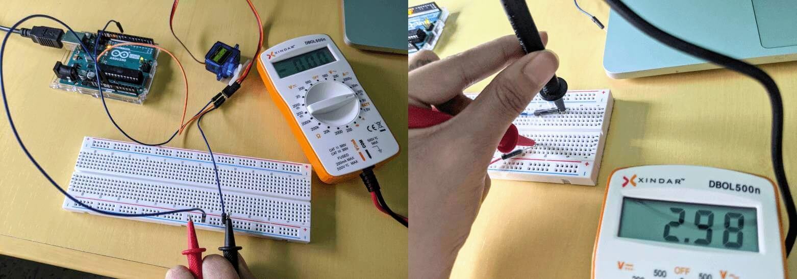
The way I wired the circuit before talking to David (the picture on the left) was totally wrong because I basically still put the multimeter in parallel. To fix that, I unplugged the jumper wires from the breadboard and instead taped them down, then I could poke the probes of the multimeter in-line. However, I could only measure a small ~3mA when my servo stayed still in its idle state. It was too tricky for me to ensure a stable connection between the jumper wires and the probes since I didn't have a soldering iron with me. Hence, I will include here the result from David. The measured current varied from ~150mA to almost ~200mA, which means the power consumption of the servo ranged from 0.75 - 0.9W with no load attached, according to the formula W = V x A:
Since my 4$ multimeter can only measure a maximum current of 200mA, I couldn't do anything further to measure the power consumption when there are loads attached. Fortunately, my classmate Benjamin Scott also performed some measurements with the same SG90 servo, and his result was that the servo can consume up to 5V x 580mA ~ 2.9W when there are torque loads.
That's it for the group assignment. More or less I understood some characteristics of the SG90 servo. I will try to do this group assignment properly by using an oscilloscope when we get back to the lab.
Making and testing basic actuators
Additional test - RGB LED
I continued to try an electroluminescence actuator: a common cathode RGB LED to which we give PWM signals to the anode of the internal red, green and blue LEDs. As per Santi's suggestion, I want to use these RGB LEDs in my Final Project as a way to help kids debug their trials: red means "Error!", green means "Success!", and yellow means "Warning!" (while there are weird conditions or behaviors detected). The wiring of the circuit was really basic: I connected the cathode of the RGB LED (the longest leg) to the GND pin of Arduino Uno and wired the other three pins to pin 9, 10, 11 through 220Ω resistors. Pin 9 was connected to the internal blue LED, pin 10 to the green one, and pin 11 to the red one. They are all PWM pins which can be used to give a desired analog output by varying the width of the pulse.
Below is the easy code I wrote to sequentially display RGB and CYMK primary colors:
    /*
     * pin variables
     */
    int r = 11;
    int g = 10;
    int b = 9;

    void setup() {
        pinMode(r, OUTPUT);
        pinMode(g, OUTPUT);
        pinMode(b, OUTPUT);
    }

    /*
     * display certain colors based on the R,G,B values of that color
     */
    void loop() {
        mix(255, 0, 0); // red
        delay(1000);
        mix(0, 255, 0); // green
        delay(1000);
        mix(0, 0, 255); // blue
        delay(1000);
        mix(255, 255, 255); // white
        delay(1000);
        mix(0, 255, 255); // cyan
        delay(1000);
        mix(255, 0, 255); // magenta
        delay(1000);
        mix(255, 255, 0); // yellow
        delay(1000);
        mix(255, 255, 255); // white
        delay(1000);
    }

    /*
     * use analogWrite() to change the intensity of 3 internal LEDs, with analog values from 0 - 255
     */
    void mix(int red, int green, int blue)
    {
        analogWrite(r, red);
        analogWrite(g, green);
        analogWrite(b, blue);
    }
The R,G,B values of a certain color can be checked here. Look at this, what a lovely thing!
Additional test - Active and passive buzzers
My next experiment was to try piezoelectric buzzers. There are 2 types of buzzer: an active buzzer that has additional circuitry in it which makes it simpler to control (turn on/off) but limits the buzzer to only one tone; and a passive buzzer which can make different tones, but the MCU has to provide an electronic signal at a desired frequency and that frequency will determine the tone. The connection was easy: (-) pin of the buzzer was connected to GND pin of Arduino Uno, and digital pin 4 of Arduino Uno was connected to the (+) pin of the buzzer.
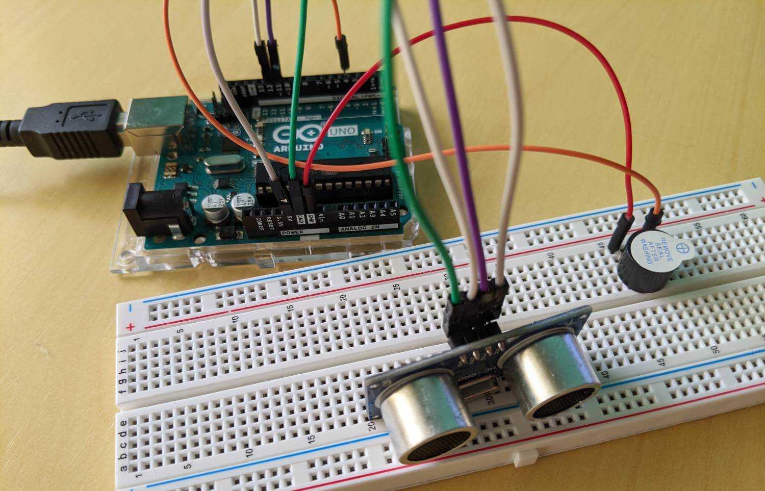
In order to test the active buzzer as an output controlled by an input, I used the HR-SC04 sensor. If the distance measured is less than 5cm, the buzzer will make a sharp alarm tone. This could be developed to a custom behavior of my dragon: whenever someone gets close to it, it will roar.
I tried to play some music with the passive buzzer, and since I'm a big fan of Super Mario, I looked for this online tutorial, mostly for the notes included in the theme song. I also wrote the functions myself and simplified the program a bit. A cheatsheet for converting notes to frequency values can be checked here.
Below are the programs I used for both buzzers:
    /*
     * pin variables
     */
    int trig = 11;
    int echo = 12;
    int buzzer = 4;

    /*
     * useful ultrasonic sensor's variables
     */
    long unsigned duration = 0;
    int distance = 0;
    const int threshold = 5;

    void setup() {
        pinMode(trig, OUTPUT);
        pinMode(echo, INPUT);
        pinMode(buzzer, OUTPUT);
    }

    /*
     * turn buzzer on/off if the distance is less than 5cm
     */
    void loop() {
        digitalWrite(buzzer, LOW);

        digitalWrite(trig, LOW);
        delay(50);
        digitalWrite(trig, HIGH);
        delay(100);
        digitalWrite(trig, LOW);

        duration = pulseIn(echo, HIGH);
        distance = (duration * 0.034)/2;

        if (distance < threshold) {
            digitalWrite(buzzer, HIGH);
            delay(1000);
            digitalWrite(buzzer, LOW);
            delay(1000);
        }

        delay(200);
    }
    /*
     * all frequency values of all notes here in case I want to try other 80s theme songs
     */
    #define NOTE_B0  31
    #define NOTE_C1  33
    #define NOTE_CS1 35
    #define NOTE_D1  37
    #define NOTE_DS1 39
    #define NOTE_E1  41
    #define NOTE_F1  44
    #define NOTE_FS1 46
    #define NOTE_G1  49
    #define NOTE_GS1 52
    #define NOTE_A1  55
    #define NOTE_AS1 58
    #define NOTE_B1  62
    #define NOTE_C2  65
    #define NOTE_CS2 69
    #define NOTE_D2  73
    #define NOTE_DS2 78
    #define NOTE_E2  82
    #define NOTE_F2  87
    #define NOTE_FS2 93
    #define NOTE_G2  98
    #define NOTE_GS2 104
    #define NOTE_A2  110
    #define NOTE_AS2 117
    #define NOTE_B2  123
    #define NOTE_C3  131
    #define NOTE_CS3 139
    #define NOTE_D3  147
    #define NOTE_DS3 156
    #define NOTE_E3  165
    #define NOTE_F3  175
    #define NOTE_FS3 185
    #define NOTE_G3  196
    #define NOTE_GS3 208
    #define NOTE_A3  220
    #define NOTE_AS3 233
    #define NOTE_B3  247
    #define NOTE_C4  262
    #define NOTE_CS4 277
    #define NOTE_D4  294
    #define NOTE_DS4 311
    #define NOTE_E4  330
    #define NOTE_F4  349
    #define NOTE_FS4 370
    #define NOTE_G4  392
    #define NOTE_GS4 415
    #define NOTE_A4  440
    #define NOTE_AS4 466
    #define NOTE_B4  494
    #define NOTE_C5  523
    #define NOTE_CS5 554
    #define NOTE_D5  587
    #define NOTE_DS5 622
    #define NOTE_E5  659
    #define NOTE_F5  698
    #define NOTE_FS5 740
    #define NOTE_G5  784
    #define NOTE_GS5 831
    #define NOTE_A5  880
    #define NOTE_AS5 932
    #define NOTE_B5  988
    #define NOTE_C6  1047
    #define NOTE_CS6 1109
    #define NOTE_D6  1175
    #define NOTE_DS6 1245
    #define NOTE_E6  1319
    #define NOTE_F6  1397
    #define NOTE_FS6 1480
    #define NOTE_G6  1568
    #define NOTE_GS6 1661
    #define NOTE_A6  1760
    #define NOTE_AS6 1865
    #define NOTE_B6  1976
    #define NOTE_C7  2093
    #define NOTE_CS7 2217
    #define NOTE_D7  2349
    #define NOTE_DS7 2489
    #define NOTE_E7  2637
    #define NOTE_F7  2794
    #define NOTE_FS7 2960
    #define NOTE_G7  3136
    #define NOTE_GS7 3322
    #define NOTE_A7  3520
    #define NOTE_AS7 3729
    #define NOTE_B7  3951
    #define NOTE_C8  4186
    #define NOTE_CS8 4435
    #define NOTE_D8  4699
    #define NOTE_DS8 4978

    /*
     * pin variables
     */
    int buzzer = A0;

    /*
     * list down all notes of the melody
     */
    int melody[] = {
    NOTE_E7, NOTE_E7, 0, NOTE_E7, 0, NOTE_C7, NOTE_E7, 0, NOTE_G7, 0, 0, 0, NOTE_G6, 0, 0, 0,
    NOTE_C7, 0, 0, NOTE_G6, 0, 0, NOTE_E6, 0, 0, NOTE_A6, 0, NOTE_B6, 0, NOTE_AS6, NOTE_A6, 0
    };

    void setup()
    {
        pinMode(buzzer, OUTPUT);
    }

    void loop()
    {
        /*
         * loop through all notes of the melody
         */
        for (int i = 0; i < (sizeof(melody) / sizeof(int)); i++) {

            // tone(pin, frequency, duration)
            // to calculate the note duration, take one second divided by the note type
            // e.g. quarter note = 1000 / 4, eighth note = 1000/8, etc.
            tone(buzzer, melody[i], 125); //1000 / 8

            // to distinguish the notes, set a minimum time between them
            delay(150); //125 * 1.2

            // stop the tone playing
            tone(buzzer, 0, 125);
        }
    }
Designing and making a board with actuators
Individual assignment - Design the ESP32 board and its motor shield
This week, I continued to design the shield which will act as a bridge between my main ESP32 board and the motors.
Designing the ESP32 board with KiCad
The ESP32 board was designed in the 9th week, but I mostly talked about how I came up with the input parts there. Here I would like to continue discussing the output parts:
- For the output parts, I was thinking about connecting the board to 2 DC motors through a motor shield which will piggyback onto the ESP32 board. A small DC motor usually has a stall torque of 0.85 kgf·cm. Stall torque is the torque load that can be applied on the device to make it stop rotating. The value of 0.85 kgf·cm means the amount torque we would get if we were to bolt a 1cm long arm to the shaft horizontally and hang a 0.85kg mass at the end of the arm. Fortunately, my Final Project doesn't require a long arm at all and it also won't weight heavier than 0.85kg x 2 = 1.7kg, therefore it might not need a stronger (and more dangerous) motor. 2 DC motors should be fine.
- For the power supply, I will go with a +1A LiPo battery, since it will be sufficient for an ESP32 MCU in active mode (~250mA), 2 DC motors that require up to 1A continuous consumption each, and other components. The motor shield will be powered first and from the shield, power will be passed to the ESP32 board and the DC motors, because if I power the ESP32 first, the current passed from the ESP32 board to the shields and the motors will be constrained to 1 Amp.
- At first, I wanted to use N-MOSFET transistors as switches to turn on 2 motors: 1 CW motor (to move forward) and 1 CCW motor (to move backward). MOSFET is basically a transistor which can cut high currents or voltages but handled by a microcontroller (interesting tutorial here). The larger the voltage we apply to the GATE, ideally, the lower the resistance, meaning the MOSFET is ON. I followed one of the solutions from this link. Little did I know that many MOSFETs ask for a minimum of 5V to be able to open a circuit. Oscar advised me to use other transistors instead, or to use commercial boards with TXS010X chips, or to look for MOSFETs with low activation voltage that can be driven by 3.3V logic. I was convinced tremendously by this thread that BSS138, 2N7000, and FDN337N work fine for most applications. They have SOT23 SMD packages available and their Vgs(th) ranges are quite low (0.5 - 1.5V for the BSS138, 0.8 - 3V for the 2N7000, and 0.4 - 1V for the FDN337N). Vgs is the voltage from gate to source and Vgs(th) is the voltage at which the MOSFET will begin to conduct or to be turned on partially. The FDN337N's datasheet also clearly states in the Rds(on) section that Vgs can go down to 2.5V TTL level.
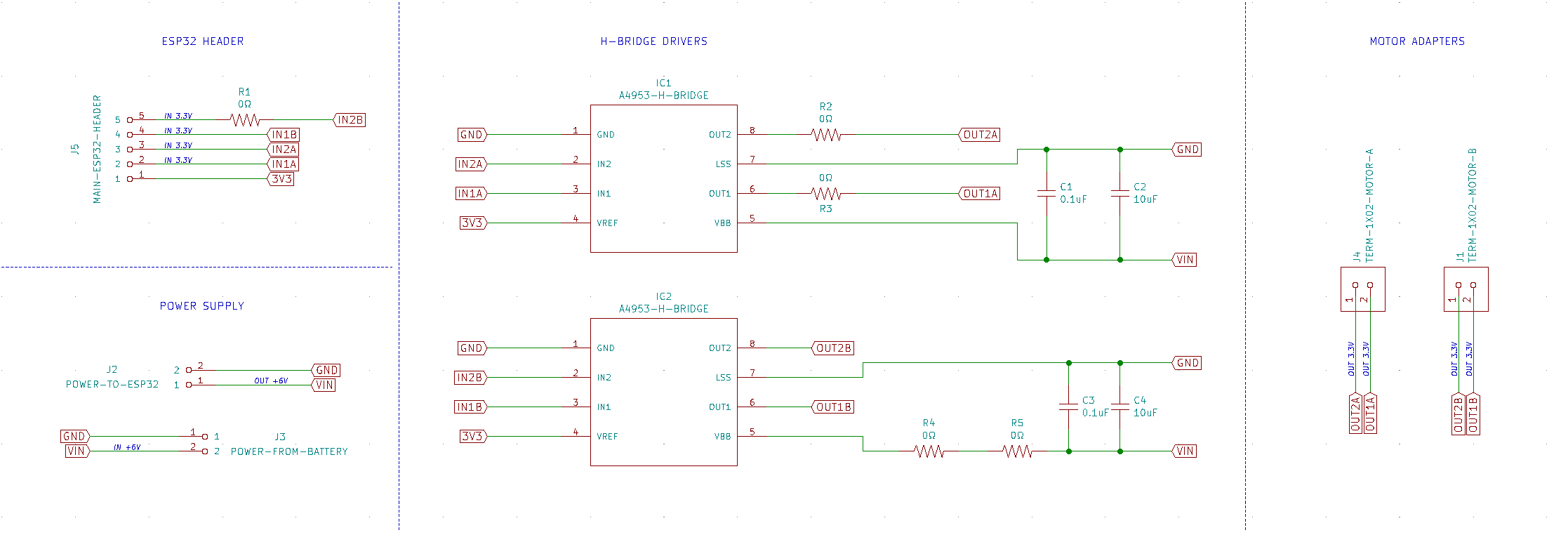
- After researching online for a while, I changed my mind and decided to control the motors with H-bridge circuits in order to make the motors rotate differently. My first idea was to use a commercial L298N motor driver, as it can handle 2 DC motors at the same time. However, it requires too many inputs (2 data inputs and 1 enabler per motor), I couldn't find available KiCad footprint, and I also want to limit the number of commercial elements used in my design. Therefore, I decided to use 2 A4953 chips to handle 2 DC motors since I saw the footprint in the KiCad library provided by the instructors. As per the data sheet, they seem to work fine with 3.3V logic inputs.
- I put other output devices such as active buzzer and RGB LED strip on the upper shield, together with the sensors. They work fine at 5V, so they won't need any external power supply or logic level shifting.
Designing the motor shield with KiCad
I took a look at this documentation to design my motor shield. But instead of using 2x2 pin headers to wire the motors onto the shield, I used a 3.5mm terminal blocks. The shield was designed during July when we got back to the lab after the lockdown, and to be honest, I was kinda tired from routing all the PCBs, so I used A LOT OF jumpers.
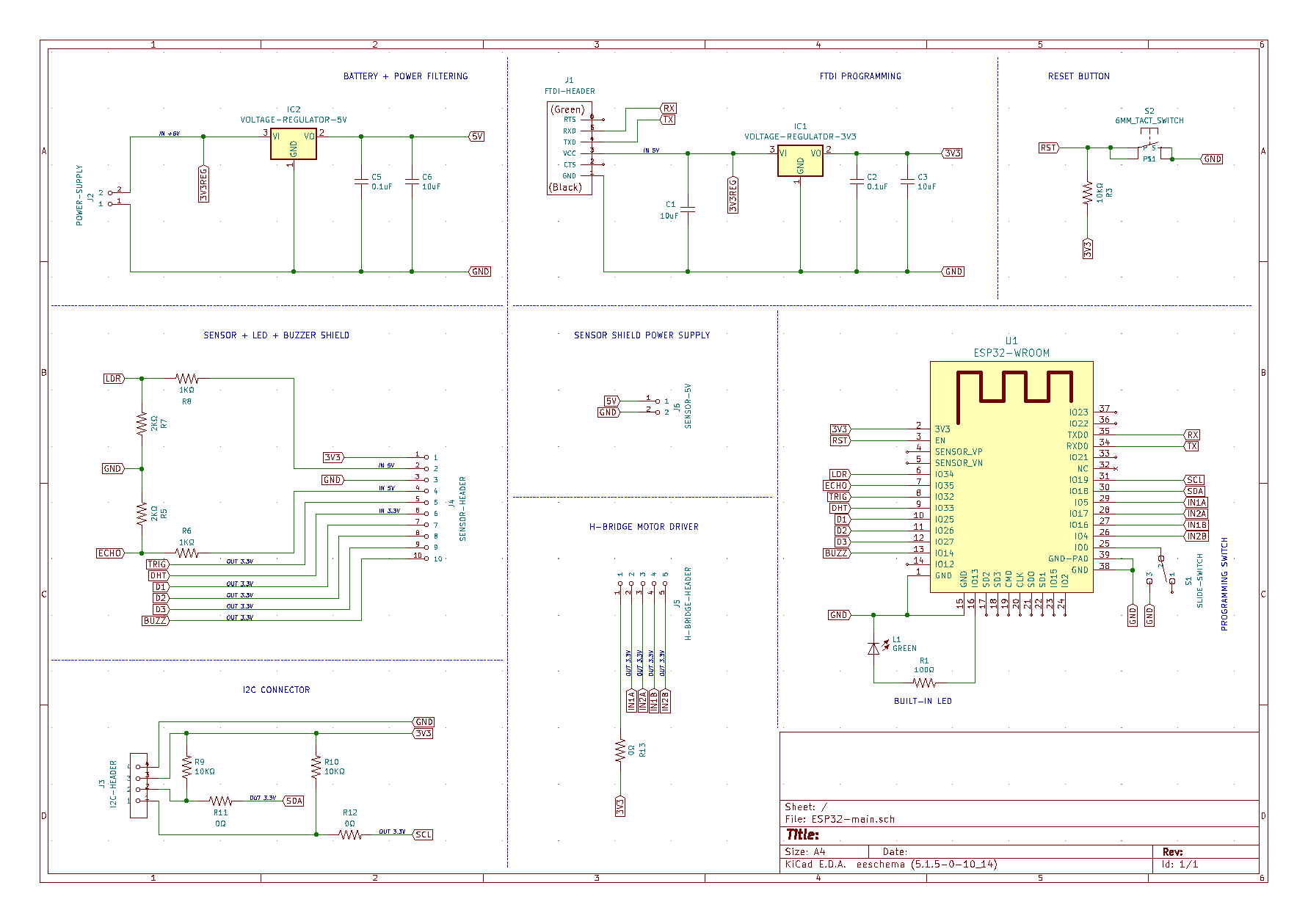
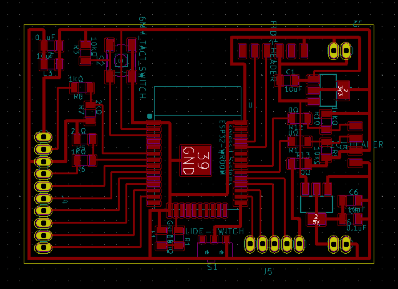
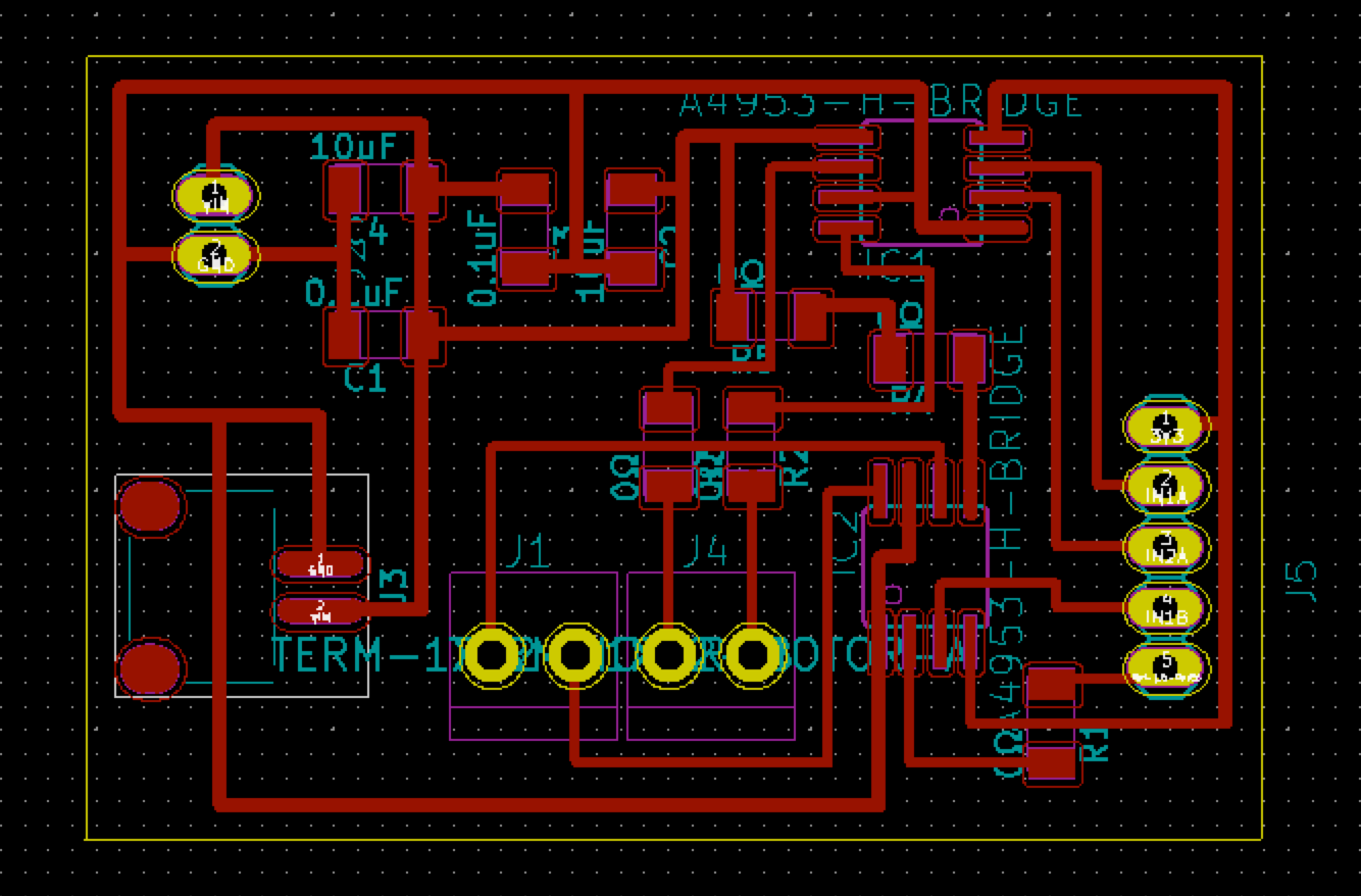
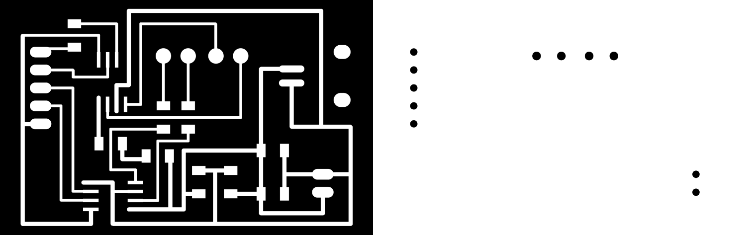
Below we have the KiCad schema and the PCB layout of the motor shield:
And below we have the fancy 3D thing:
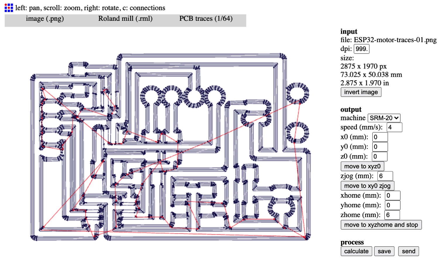
Milling and soldering the boards
Not much to say about the milling and soldering process:
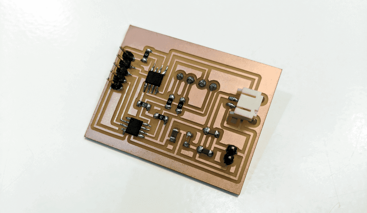
Here I have a little problem while trying to power the motor shield. I placed the footprint of the JST battery connector in the wrong direction, hence I couldn't plug the jack onto it. To avoid re-designing the shield, I cut, swap, and re-solder the wires of the battery as the image below:
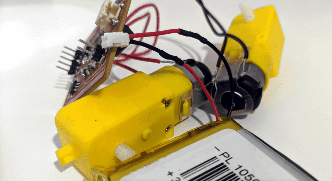
Finally, it's time to assemble the shields. I was super satisfied to see this BIG MAC of PCBs. Om nom nom!
Programming the board and driving actuators
First, I tested the buzzer and an LED strip of 3 pixels with the below code. There are basic NeoPixel examples that can be found everywhere online. However, I still put some comments here:
    /*
     * libraries and pin variables
     */
    #include <Adafruit_NeoPixel.h>
    #define BUILTIN_LED 13
    #define BUZZ_PIN 14
    #define RGB_PIN 26

    // number of pixels in NeoPixel strip
    #define LED_COUNT 3
    // declare NeoPixel strip object
    Adafruit_NeoPixel strip(LED_COUNT, RGB_PIN, NEO_GRB + NEO_KHZ800);

    /*
     * initialize NeoPixel strip object
     */
    void setup() {
        pinMode(BUILTIN_LED, OUTPUT);
        pinMode(BUZZ_PIN, OUTPUT);
        strip.begin();
        strip.show();
        strip.setBrightness(50);
    }

    void loop() {
        digitalWrite(BUZZ_PIN, HIGH);
        delay(1000);
        digitalWrite(BUZZ_PIN, LOW);
        delay(1000);

        colorWipe(strip.Color(255, 0, 0), 50); // red
        colorWipe(strip.Color(0, 255, 0), 50); // green
        colorWipe(strip.Color(0, 0, 255), 50); // blue

        digitalWrite(BUZZ_PIN, HIGH);
        delay(1000);
        digitalWrite(BUZZ_PIN, LOW);
        delay(1000);

        rainbow(10);

        digitalWrite(BUZZ_PIN, HIGH);
        delay(1000);
        digitalWrite(BUZZ_PIN, LOW);
        delay(1000);

        theaterChase(strip.Color(127, 127, 127), 50); //white, theater chase effect

        digitalWrite(BUILTIN_LED, LOW);
        delay(1000);
        digitalWrite(BUILTIN_LED, HIGH);
        delay(1000);
    }

    void colorWipe(uint32_t color, int wait) {
        for(int i = 0; i < strip.numPixels(); i++) {
            strip.setPixelColor(i, color);
            strip.show();
            delay(wait);
        }
    }

    void theaterChase(uint32_t color, int wait) {
        for(int a = 0; a < 10; a++) {
            for(int b = 0; b < 3; b++) {
            strip.clear();
            for(int c = b; c < strip.numPixels(); c += 3) {
                strip.setPixelColor(c, color);
            }
            strip.show();
            delay(wait);
            }
        }
    }

    void rainbow(int wait) {
        for(long firstPixelHue = 0; firstPixelHue < 5*65536; firstPixelHue += 256) {
            for(int i = 0; i < strip.numPixels(); i++) {
                int pixelHue = firstPixelHue + (i * 65536L / strip.numPixels());
                strip.setPixelColor(i, strip.gamma32(strip.ColorHSV(pixelHue)));
            }
            strip.show();
            delay(wait);
        }
    }
They seem to work totally fine. After designing the dragon's head, I can have more data lines and try many more effects.
Next, I tried to test the motor shield and the DC motors with a basic moving forward sketch and the +3.7V 2000mA LiPo battery. The DC motors (3-12V) did not work, and I started debugging step by step. The pin numbers were carefully double-checked, and the sketch was very simple, so I was pretty sure the problem was with the electronic parts:
    /*
     * libraries and pin variables
     */
    int motor1Pin1 = 4;
    int motor1Pin2 = 16;

    void setup() {
        pinMode(13, OUTPUT);
        pinMode(motor1Pin1, OUTPUT);
        pinMode(motor1Pin2, OUTPUT);
        Serial.begin(115200);
    }

    void loop() {
        digitalWrite(13, HIGH);
        delay(500);
        digitalWrite(13, LOW);
        delay(500);
        /*
         * moving forward
         */
        digitalWrite(motor1Pin1, LOW);
        digitalWrite(motor1Pin2, HIGH);
        delay(2000);
    }
The LED could blink on and off so I knew that the power was transferred safely from the battery to the motor shield and then the ESP32 board. With the help from Oscar and Josep, we supplied a 5V power to the shield and used the multimeter to thoroughly test these following points:
- When we connected the motors and the battery directly, the motors rotated. Hence, we could confirm that the battery and the motors work fine.
- We checked the VREF and voltage levels from the ESP32 micro-controller to the input pins of the A4953 H-Bridge chip. The pin which was written LOW showed 0V and the pin which was written HIGH showed ~3.3V. So these parts were fine.
- Next, we checked the voltage levels from the output pins of the H-Bridge chip to the terminal blocks. Both of them showed ~4.8V. After checking again from the code to the schema of the motor shield, then the datasheet of the A4953 H-Bridge chip, we still couldn't figure out why the A4953 chip didn't do what it should do. I even re-soldered and replaced the chips with new ones, but the motors were still motionless.
After reading all topics and articles related to the A4953 chip, I found this documentation from a CBA student. There are magic lines from the beginning of the documentation which states that the A4953 chip is an automotive-grade chip that has under-voltage protection at 7.9V. That means if it detects input voltage less than 7.9V, it will not output anything. We then supplied a 9V power to the motor shield, and finally, the motors turned alive!
Conclusion
It was really amazing to be able to finish the most crucial electronic parts of my Final Project. It might not be too ambitious, but I learned a lot from working on it step by step. I can't wait to finish the proper networking and programming parts, stay tuned!