This week's assignment is to answer key questions regarding the Final Project.
Due to the COVID-19 lockdown, we have a whole month to work from home and to me, life became less hectic. Finally, I could sit down and make a plan of what to do for my Final Project. This week's assignment seems to be useful, since I could write down some crucial questions and see where will my Final Project go.
Concept
What will my Final Project do?
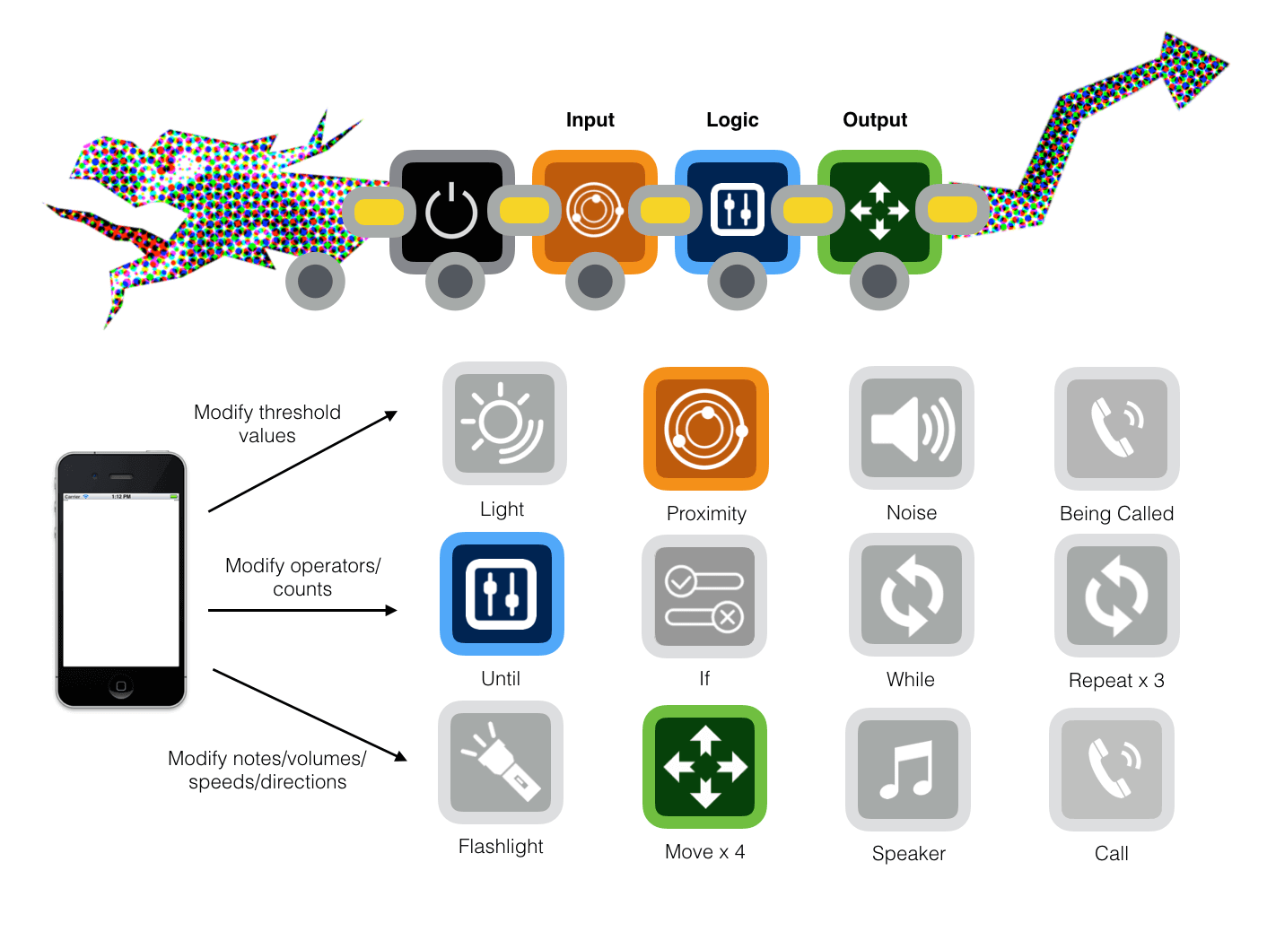
My idea is to create an off-the-screen and modular robot with customizable behaviors that can give preschoolers the basic ideas of programming and robotics. There will be 3 groups of blocks: Input, Logic, Output. Kids will need at least one block of each group to perform the desired task. I want the robot to symbolize a cool and modular animal, hence, I sketched here a dragon with customized habits that can be defined by kids through a trial-and-error process:

My MVP for Fab Academy will have 2 Input blocks (including Proximity and Dark), 2 Output blocks (including Move Forward and Flashlight), and at least 2 Logic blocks (including If and Until). It would be nice if I could have enough time to build more blocks and a mobile/web app which is connected to a Scratch account and is able to execute further complicated tasks.
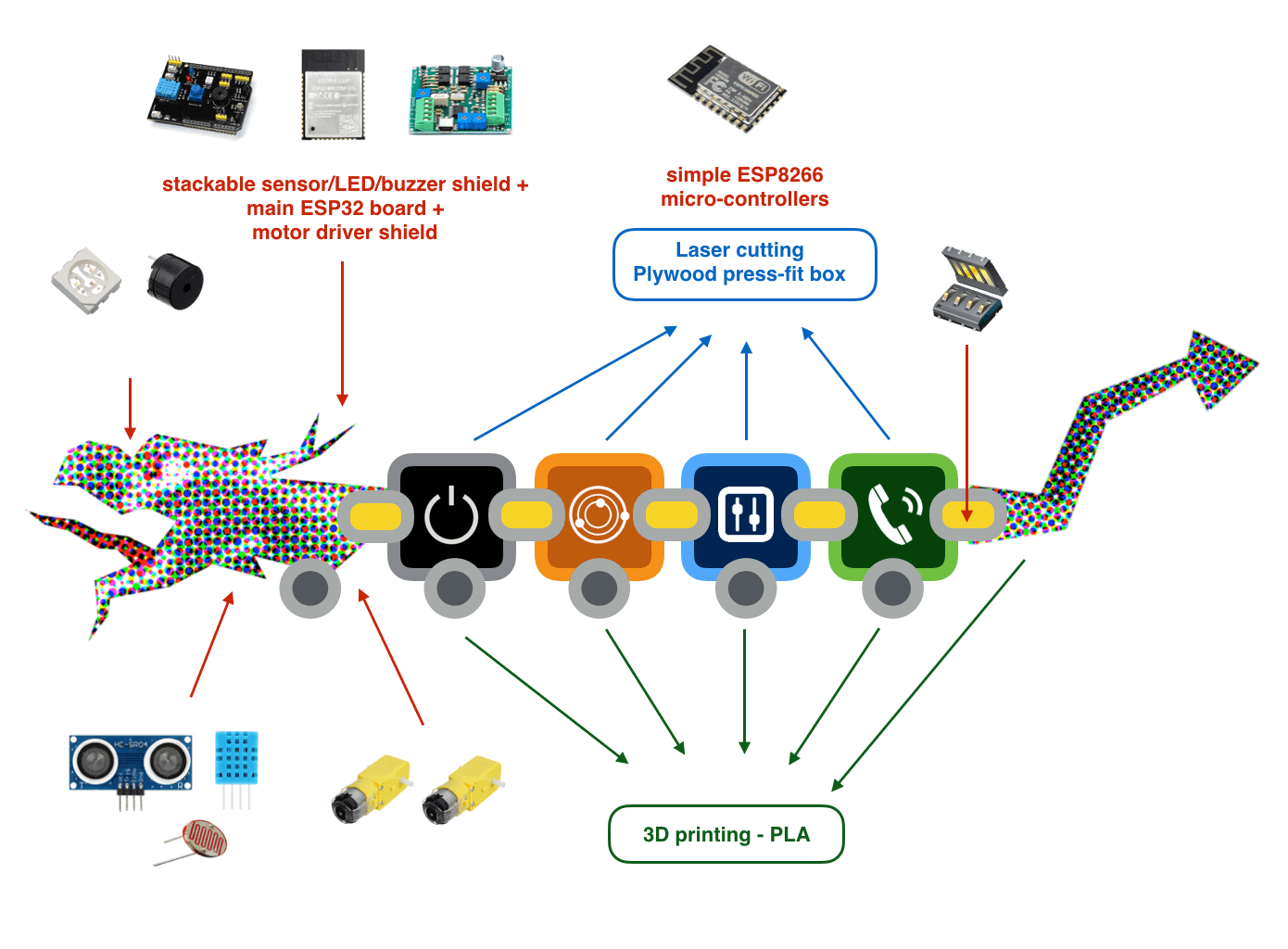
The below pictures show how I'm planning to connect the block physically and electrically:

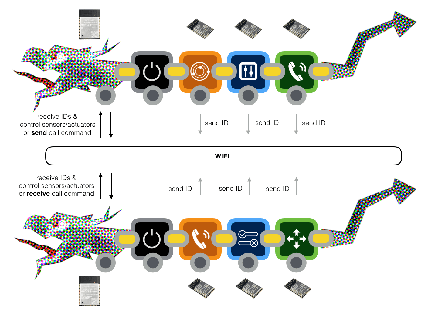
And how I'm planning to exchange and process data between them:

Who has done this idea before?
I found some STEAM toys (which are quite successful) with a similar idea:
Some cool projects by the alumni of Fab Academy and MIT's CBA that are related to my idea:
- Self-built IoT devices from LEGO bricks
- DIS/ORDER modular circuit
- Soldercubes self-soldering modular robot
- Interactive cardboard cubes
What makes my Final Project different?
- The Debugging process: After immersing myself into technology for a while, I realized the most crucial skill kids need to develop is a debug mindset. My robot should be able to inform kids (or parents) whether each step is successful or there is an error at some point via an LCD screen, a buzzer or colorful LEDs.
- The Logic blocks: Other toys usually simplify the Input-Output relationship with a default If-Then logic. I'd like to invest further in different types of programming concepts. They could be other flow controls (while, for, iteration loop) or operators (and, or, greater than, less than, equal).
- An Object-Oriented approach: I'm thinking about how to resemble a function with those blocks, maybe with a Call output and a Being Called input. This could be something very interesting since my dragon could be considered as an object and would be able to perform communication.
Project development plan
What will I design?
The design tasks of my Final Project will be divided into 3 parts. The first step will be designing the electronics parts of my project. After making all the electronics parts work perfectly, I can move on to 3D modeling my MVP. Then if I have enough time, I will continue to work on a user interface.
- Electronics: I plan to have a central micro-controller that will manipulate all the input and output devices of my Final Project. Hence, I will design 3 PCBs: an ESP32 compatible main control board, a multi-sensor shield, and a multi-actuator shield. There will also be simple ESP8266 boards included in blocks, simply holding texts referring to their IDs.
- Housing: I will design the dragon itself (its head and tail) and the above-mentioned blocks (Proximity, Move Back, Dark, Flashlight, If, and Until). As for the body of the dragon and the blocks, I plan to use Fusion 360 in order to design them parametrically and enhance accuracy. The low-poly head and tail of the dragon could be designed in Blender.
- Interface: I'm thinking about designing a mobile/web interface with which users can monitor the activities of each element of the robot. The mobile/web interface should be accessible through a web browser/Android emulator. It would be nice if users can modify threshold values of sensors, motors' speed and direction, etc. This part is totally optional.
What parts and systems will be made?
Parts that I will make: the ESP32 compatible main control board, the ESP8266 boards within blocks, the FTDI programming chip, the multi-sensor shield, the multi-actuator shield, the dragon's body and the blocks, and the mobile/web interface (optional).
Parts that I will buy instead: connectors between PCBs, external power supply, sensors (HR-SC04 ultrasonic sensor, LDR/photoresistor, DHT11 temperature/humidity sensor) and actuators (RGB LED strip, mini DC/servo motors with gears and wheels, active buzzer).
What processes will be used?
For the electronic parts, I will use KiCad to design the schema and PCB layouts, Fab Modules to generate toolpaths, and the Roland SRM-20 machine to mill the boards. I will program the boards with Arduino IDE or PlatformIO. For the blocks, I will design with Fusion 360 and laser-cut them using the TROTEC Speedy 400 machine. For the 3D printing parts, I plan to use Fusion 360 and Blender to design them, and they will be printed using Creality CR-10 or Prusa i3 printer.
My weekly schedule starting from the 9th week:
| Final Project requirement | Final Project scope | Process | CAD/EDA software | CAM software | Programming IDE | Machine | Material | Timeline |
|---|---|---|---|---|---|---|---|---|
| Subtractive fabrication | Press-fit blocks | Laser-cutting | Fusion 360 | Rhino + TROTEC JobControl | N/A | Trotec Speedy 400 | Acrylic 4mm | Week 15-18 |
| Additive fabrication | Dragon's head, tail, and adapters | FDM 3D printing | Fusion 360 + Blender | Ultimaker Cura | N/A | Creality CR-10 S5/ Prusa i3 MK3S | PLA 1.75mm | Week 15-18 |
| Electronics design & production | Micro-controller boards, multi-sensor/actuator shields | PCB milling & soldering | KiCad | Fab Modules | N/A | Roland MonoFab SRM-20 | PCB 50 x 70 x 1.6mm | Week 9-13 |
| Embedded micro-controller programming | Micro-controller boards, mobile/web interface | Embedded programming | N/A | N/A | Arduino IDE/ PlatformIO | N/A | N/A | Week 13-16 |
Bill of materials (BOM)
What materials and components will be used?
For the blocks, I will use plywood 4mm or cast acrylic 3mm. For the 3D printing parts, I plan to use PLA 1.75mm. For the PCBs, I will use one-sided copper PCB 50 x 70 x 1.6mm available at Fab Lab Barcelona.
I plan to use the ESP32 chip as the central micro-controller for a couple of reasons:
- I can program the ESP32 chip without using an external ISP. ESP32 chips can be programmed in many developing environments and programming frameworks (Arduino, ESP-IDF), and they are also compatible with Arduino IDE. My previous experience with the Barduino ESP32 board was really comfortable.
- The ESP32/ESP8266 chips can communicate with each other via Wifi without an extra Wifi module. In fact, most of the Arduino boards' Wifi modules I know are using ESP32 or ESP8266 chips.
- I think the ESP32 chip is really powerful. It has a lot of memory, many GPIO pins and many ADC channels. It also supports a wide range of serial communication protocols. I may not be able to leverage its full potential, but I don't want to try other families without understanding their limitations. ESP32 might be redundant, but secure.
- Finally, our instructor Eduardo Chamorro has designed an ESP32 compatible board Barduino 2.0, and I feel more confident to build on top of it rather than designing a whole new board myself, since my knowledge of electronics is still extremely limited.
I also bumped into this article while studying the ESP32 and ESP8266 chips, and the idea of stackable shields seemed to be what I'm looking for. To stack/connect and power the boards, I might need external power supply, JST jacks, normal pin headers/sockets and magnetic connectors. I'm considering using these sensors and actuators: HR-SC04 ultrasonic sensor, photoresistor, DHT11 temperature/humidity sensor (optional), WS2812B RGB LED strip, DC motors and A4953 H-bridge drivers, active buzzer (optional).
Another thing I might need to deal with is level shifting from a lower voltage to a higher voltage and vice versa. For example, the working voltage of my ESP32 board is around 3.3V and its GPIO pins are not 5V tolerant. However, all the sensors I'm going to use will only operate at 5V. I'm not sure about the required voltages of the motors yet, but I think they will be greater than 6V, up to 12V. Hence, I might need level shifters and LDO regulators for controlling the appropriate input voltages of all the components. Of course, there will be the ESP8266 chips which will be included in blocks, capacitors, resistors, diodes, switches, and LEDs for power status and debugging.
Where will they come from?
Most of the laser-cutting/3D printing/PCB milling materials and electronic components are available at Fab Lab Barcelona. Some specific modules can be ordered from Amazon, Mouser Spain or DigiKey.
How much will they cost?
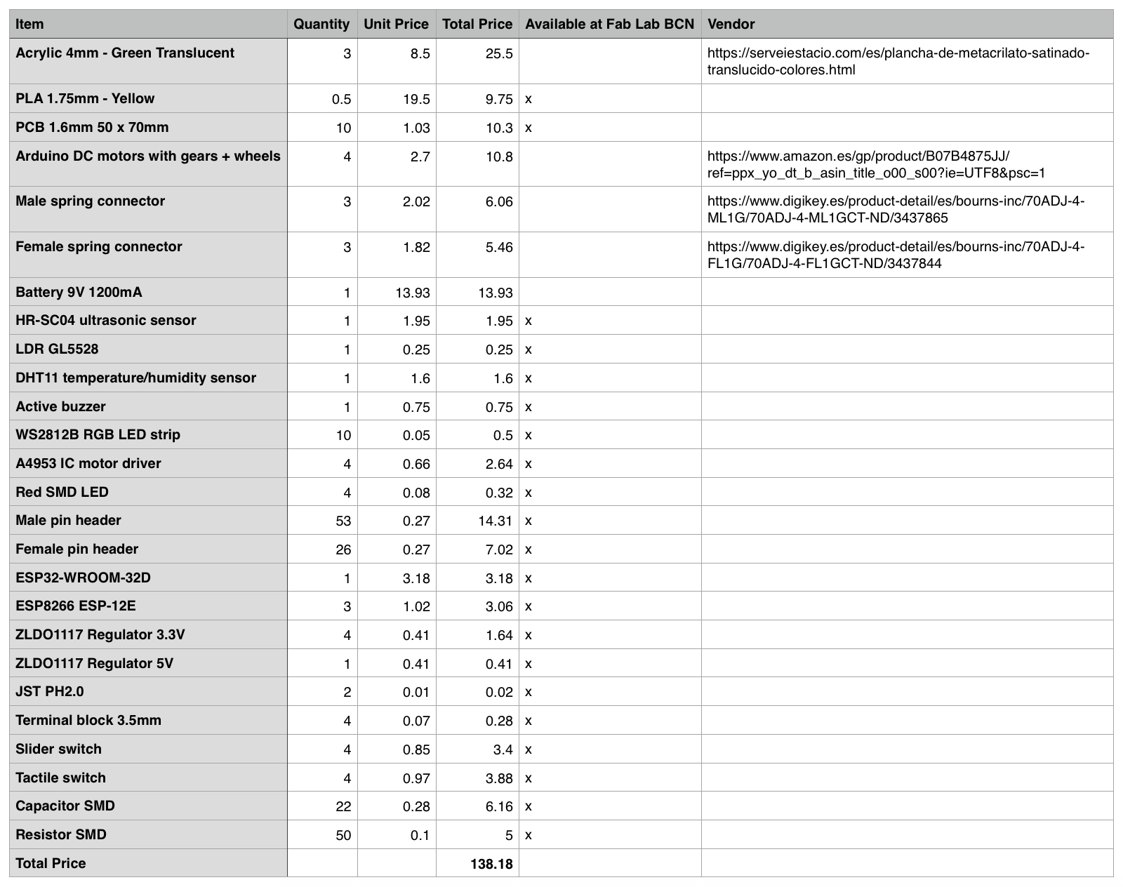
Below is just a DRAFTED bill of materials for 1 dragon and 3 blocks which resulted in ~ 138€. The .csv file can be downloaded here.

Challenges and evaluation criteria
What questions need to be answered?
I will try to answer these questions in the upcoming classes:
- How can I simplify the electronic parts of the blocks in order to make them cheaper and simpler to fabricate? Is there any way I can send a unique ID of a block without having an ESP8266 board being powered, programmed, and registered?
- What is the best strategy to manage different voltages required by different components (3.3V, 5V, 6V)? Will 6V be enough to drive a series of DC/servo motors? Can 4 micro servos or 2 DC motors move a whole dragon? Do I really need a series of small motors?
- Will using the Wifi modules enough for all the functions I'd like to demonstrate? What could be the best way to manage the data flows? Should I simplify the main control board and add more functions to the blocks instead?
- How will the robot help kids debug their trials? Using a speaker? LCD? LEDs? Which is the most effective way?
How will it be evaluated?
For the Final Project prototype, it should be able to demonstrate clearly all the Input-Logic-Output combinations. It should also look clean and nice as an almost-there product. In the long run, users' feedback will be the most important way to evaluate the performance of my Final Project. In the future, it would be great if I can start a Kickstarter campaign to see whether users will support it. For now, I will be satisfied with my nephews loving it.