This week's assignment is to read a micro-controller data sheet (individual); to program the designed board (individual); to compare different architectures (in-group).
* All source and config files can be downloaded here.
* To keep the momentum of the 4th and 6th weeks, I tried to write down what I understand about the embedded development process.
* I need to individually read a micro-controller data sheet and program the board previously designed in the 6th week.
* This week's group assignment is to compare the performance and development workflows of different micro-controller families.
Understanding the embedded systems and programming process
I personally find the theory sections I wrote down during electronics weeks to be really useful since they helped me organizing completely new pieces of knowledge. This week, guest instructor Guillem Campodron gave us a very informative session which untangled many concepts I didn't understand about embedded systems. Embedded systems are self-contained control systems or computer systems designed for a particular purpose with bare necessary peripherals needed to run it. The core part of the embedded system is the processor (could be a micro-controller, an FPGA, or an SoC). Different interfaces (parallel or serial communication interfaces, Wifi, USB, etc.) and peripherals (displays, SD cards, input and output devices, etc.) are interfaced to the system.
I also took a look at this book to get to know better how to program my tinyAVR board. In short, in order to write software to target hardware, we need to go through a process of coding, compiling and flashing the programs into the chips. Allow me to go through a very long note without any images attached, or go straight to the assignments below.
Target hardware - Micro-controller unit (MCU)
A typical micro-controller includes a core (a processor, memory, clocks, and input/output pins) and peripherals on a single chip. The micro-controller controls a singular function by interpreting data received from I/O peripherals using the central processor. The temporary information that the micro-controller receives is stored in its data memory, where the processor accesses it and uses instructions (firmware) stored in its program memory to decipher and apply the incoming data. It then uses its on-chip I/O peripherals to communicate and enact the appropriate action. There are many available micro-controller families, some of them are widely used such as AVR (tinyAVR and megaAVR), ARM (ARM-x, Cortex-A/R/M), or Xtensa (ESP32, ESP8266), etc. For example, the ATTiny1614 chip used in my LED dice board is from tinyAVR family. Due to the COVID-19 outbreak situation, we were also provided by the instructors an Arduino Uno board with ATmega328P chip, NodeMCU board with ESP8266MOD chip and a Barduino board with ESP32-WROOM chip.
The core: Processor, Memory and I/O
- Central processor (similar to CPU on a computer): ranging from small and simple 4-bit processors to complex 64-bit processors. For example, my ATtiny1614 micro-controllers uses the 8-bit AVR processor. A processor can be considered as the brain of the device. It can respond to events and perform basic logic and I/O operations. It also performs data transfer operations, which communicate commands to other components in the larger embedded system.
- Memory: volatile memory (RAM) for temporary data storage and read-only ROM, EPROM, EEPROM or Flash memory for program (instructions) storage.
- Clocks: micro-controllers need a clock signal to trigger their command signals/instructions according to the conditions/timings set by the program.
- Inputs and outputs (GPIO controllers).
I/O peripherals (on-chip)
Peripherals are devices that aid the micro-processor to accomplish a given job. Depending on their location, they can be classified into 2 types. If they are located inside the micro-controller chip, they are called on-chip peripherals. If they are located outside the chip but on the same PCB, they are called off-chip peripherals. Some examples of on-chip peripherals:
- Analog-to-digital converters (ADC) or digital-to-analog converters (DAC): An ADC converts analog signals to digital signals and allows the processor to interface with external analog devices, such as sensors. A DAC allows the processor to communicate its outgoing signals to external analog components.
- Serial communication controllers: allow the micro-controller to communicate with external components. They have a similar function to a USB or a parallel port but differ in the way they exchange bits: I2C, SPI, UART. In short, UART is useful for communicating with computers, radio modems, and GPS units. SPI is good for ultra-fast communication over very short distances with peripherals like memories, ADCs, and DACs. I2C is a good choice for devices that move around a moderate amount of data and connect to multiple sensors and motors. More information can be found here.
- In-circuit programming and in-circuit debugging support.
- Interrupt controllers: listen to the peripherals for events and report to the processor once events occur. The particular event that we need to listen to can be programmed and unnecessary events can be ignored. Once a registered event happens, the interrupt controller goes and tells the processor about it, so that the processor can take appropriate actions.
Coding/Compiling/Linking/Debugging - Toolchain
A toolchain is a set of software development tools that are chained together as a cycle of specific stages such as code, compile, run and debug. GNU toolchain which consists of a C compiler is widely used in programming embedded systems and most toolchains are developed base on GNU (for instance, AVR GNU toolchain and ARM GNU toolchain). A toolchain usually consists of:
- Editor: editing source code to control embedded systems. It could be a standalone application or built into an IDE/IDP.
- Compiler: transforming the code into object code written by low-level language that a machine can understand. GCC is the compiler included in GNU toolchain. Make is an automation tool for compiling and building programs using avr-gcc compiler and avrdude programmer, hence it can transfer the
.hexfile into the target chip. - Assembler: converting assembly code into executable machine code. It takes the basic commands and operations from assembly code and converts them into hex/binary code that can be recognized by a specific type of processor. IDEs often include assemblers.
- Linker: combining all small pieces and modules of code together, creating an executable program. The linker of GNU toolchain is called ld.
- Debugger: testing and debugging programs. There are both source-level debugger or machine-language debugger. GDB is the GNU debugger.
- Integrated development editor/platform: An IDE/IDP often consists of a source code editor, a compiler, a linker, and a debugger. Arduino IDE and Atmel Studio are widely used by electronics lovers, and we were also introduced to PlatformIO by our instructor Oscar.
- Libraries: collections of code, such as an API, that allow the app to reference prebuilt functions or other resources. glibc provides the core libraries for the GNU system as well as many other systems that use Linux as the kernel.
- Frameworks: an abstraction layer in which software providing generic functionality can be selectively changed by additional user-written code. Some examples: Arduino framework based on Wiring (AVR, ARM), CMSIS framework (Cortex-M/A), ESP-IDF framework (ESP32), etc.
In summary, a toolchain is able to compile source code written in a high-level language into executables that can run on target devices. Most of the programs are written in C/C++, but there are also interpreters such as Espruino that supports writing code in JavaScript and MicroPython that supports writing code in Python 3. Both of them also have their own compatible hardware and software as well as unique features.
Flashing - In-system programmer
To flash a program to a chip, we might need extra hardware (an ISP) and software (the program that will communicate with the hardware programmer). I wrote about ISPs before, in the 4th week. Basically, an external ISP is an extra bit of hardware that connects between a host computer and the target board and allows the microcontroller to be programmed. Besides, depends on the chip, sometimes we have bootloader which is a piece of firmware stored in ROM that allows installing new firmware without the need of an external programmer.
In many cases, we need programming utilities to download and upload the on-chip memories. avrdude is a flashing utility working with avr-gcc compiler/linker and can be used effectively via the command line or within Arduino IDE. Other examples are pyupdi (AVR chips - UPDI interface), edbg (ARM chips - CMSIS interface) or esptool.py (Espressif chips), etc.
Understanding electronics data sheets
Individual assignment - Read the ATtiny1614 data sheet
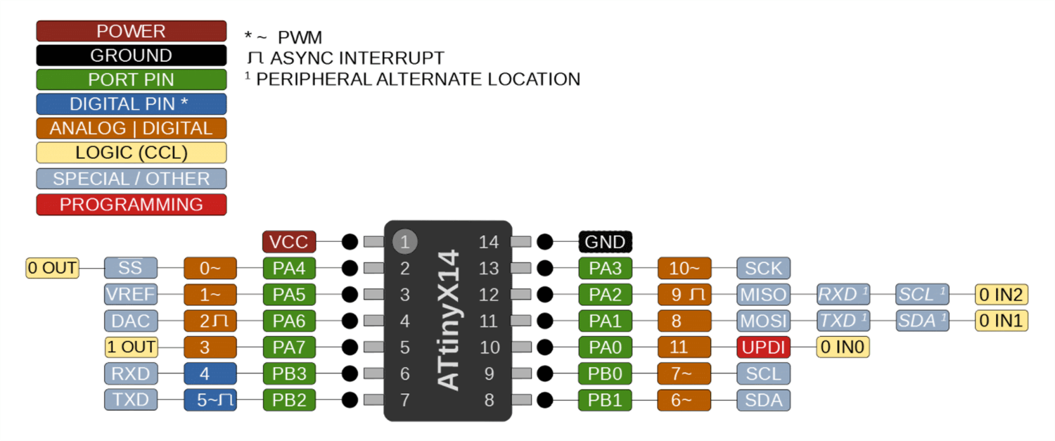
I indeed took a look at this pinout diagram and this data sheet BEFORE designing my board in the 6th week in order to know where should I connect the FTDI and UPDI headers to the chip. The RXD pin of the chip will be connected to the TX pin of the FTDI header, and the TXD pin of the chip will be connected to the RX pin of the FTDI header. This is the basic of UART serial communication.
Here are some specs of the ATtiny1614 chip:
- Flash (program memory): 16384 bytes
- EEPROM: 256 bytes
- RAM: 2048 bytes
- General-purpose I/O Pins: 12 (11 usable)
- Digital pins: 2
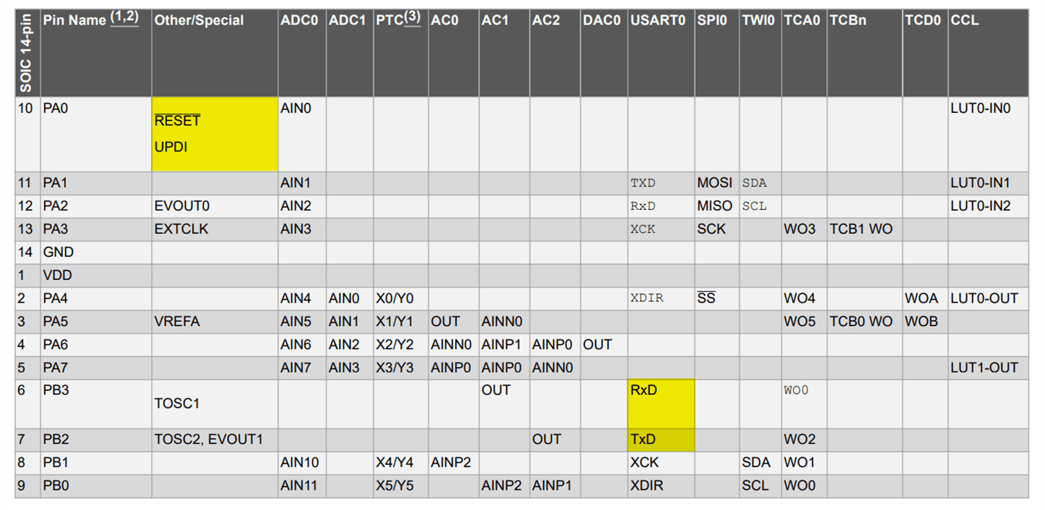
- ADC pins: 9 usable pins (pins marked with green color except for pin PA0). These pins must be used to read analog sensors.
- PWM pins: 5 pins (pins marked with orange color and a ~ sign). These pins must be used to write PWM signals.
- DAC: Yes
- Serial communication: UART, SPI, I2C
- Programming: UPDI
- Working voltage: 1.8 - 5.5V
In order to access the I/O pins and their various functions from within our code, we need to read from/write to I/O registers of the chip. The programmer uses I/O registers to provide interfaces to the I/O peripherals of the micro-controller. Generally, registers are pins, and for each pin, there is a Data register (PORTx), a Data direction register (DDRx), and a Port input register (PINn). DDRx registers configure pins as INPUT (0) or OUTPUT (1). PINx registers store a value that can be read from the register in case it is defined as INPUT. PORTx registers write the value to pins as HIGH (1) or LOW (0). Each I/O register has a name (used by high-level language/C programmer); I/O address and an SRAM address (used in low-level assembly language).
A summary of ATtiny1614's I/O pins and how to use them:
- GND: ground
- VCC: power supply
- PA0 - UDPI/RESET: programming (UPDI interface) & reset pin
- PA6 - DAC: digital to analog converter
- PA5 - VREF: the voltage reference pin used to enhance the accuracy of analog reading/writing. This pin acts as a very precise analog 'meter stick' against which the incoming analog signal is compared (as in an ADC) or the outgoing analog signal is generated (DAC).
- PA1, PA2, PA3, PA4 - MOSI, MISO, SCK, SS: Master Out Slave In, Master In Slave Out, Serial Clock and Slave Select logic signals in SPI serial communication.
- PB0, PB1 - SCL, SDA: Serial Clock and Serial Data lines in I2C serial communication. PA1 and PA2 can also be used for the same purpose.
- PB2, PB3 - RXD, TXD: Receive and Transmit functions in UART serial communication. PA1 and PA2 can also be used for the same purpose.
In the case of ATtiny1614, pin names are of type Pxn, with x being the PORT instance (A, B) and n the pin number. Notation for signals is PORTx, DDRx, and PINn. The numbers 0-10 (marked with orange and blue colors) can also be used while programming in order to indicate the pins we want to refer to.
Embedded programming
Individual assignment - Program the designed ATtiny1614 board
Arduino IDE + Arduino framework + UPDI programmer + pyupdi
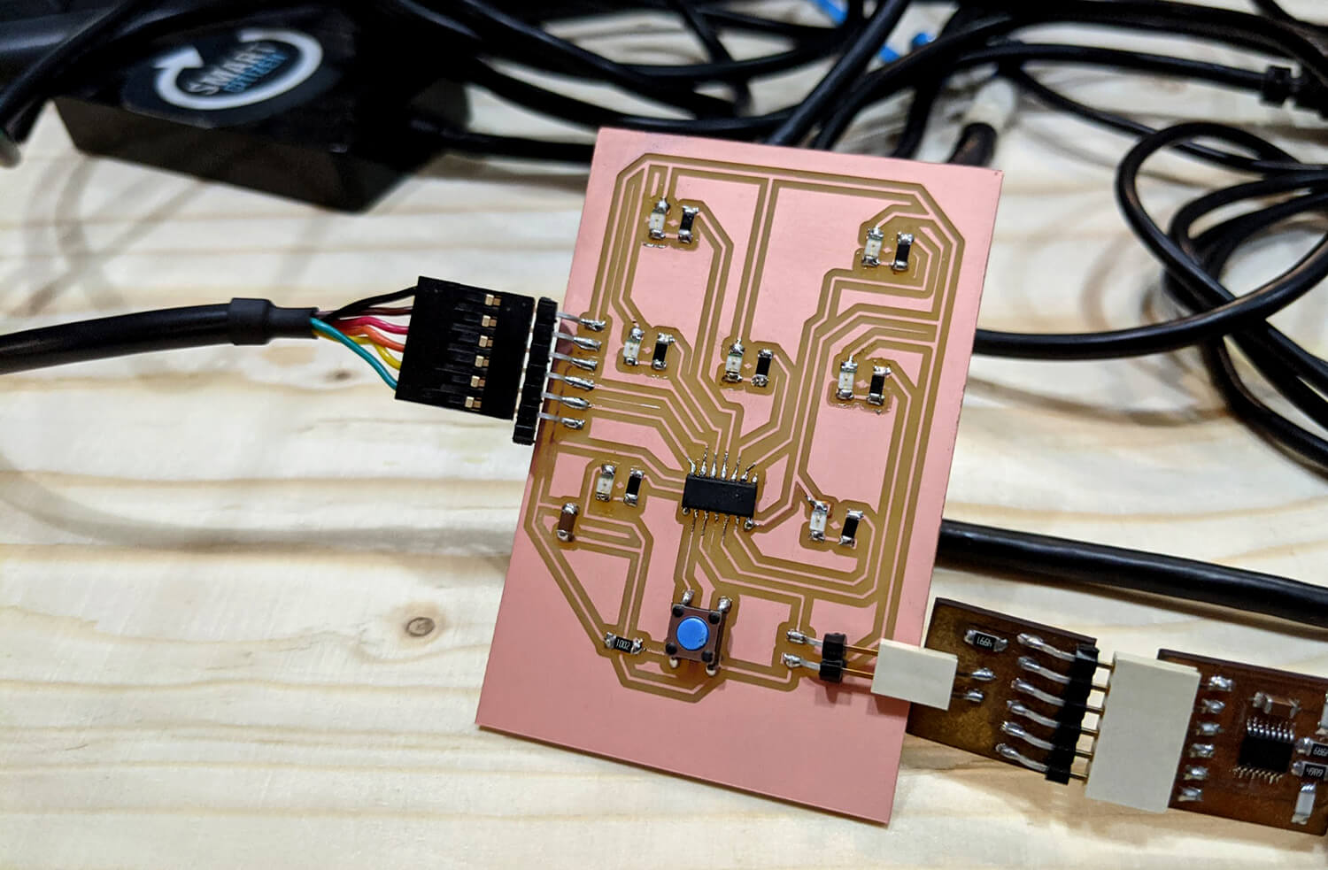
Let's take a look at my LED dice case as an example of the process: after compiling the C++ source code and linking with the AVR GNU toolchain, the Arduino IDE employs avrdude to convert the executable code into a .hex file. The .hex file then is loaded into the ATtiny1614 board via an external UPDI programmer (that I made during the 4th week), with the support of pyupdi driver.
pyupdi can be installed using pip: $ pip install https://github.com/mraardvark/pyupdi/archive/master.zip.
Below is the C++ code for a LED dice which was written in Arduino IDE using the Arduino framework:
    /*
     * assign pins to variables
     */
    int LED_1 = 8;
    int LED_2 = 9;
    int LED_3 = 1;
    int LED_4 = 0;
    int LED_5 = 10;
    int LED_6 = 3;
    int LED_7 = 2;
    int BUTTON = 7;

    /*
     * some useful variables to be used inside functions
     */
    int displayTime = 2000;
    int pendingTime = 100;
    int num = 1;

    /*
     * setup function, to run once
     */
    void setup() {
        pinMode(BUTTON, INPUT);
        pinMode(LED_1, OUTPUT);
        pinMode(LED_2, OUTPUT);
        pinMode(LED_3, OUTPUT);
        pinMode(LED_4, OUTPUT);
        pinMode(LED_5, OUTPUT);
        pinMode(LED_6, OUTPUT);
        pinMode(LED_7, OUTPUT);
    }

    /*
     * loop function, to run repeatedly
     */
    void loop() {
        // because I used a pull-up resistor, when the button is pressed, the value is LOW
        if (digitalRead(BUTTON) == LOW) {
            // get a random number from 1 to 6
            num = random(1, 7);
            // pass the random number to displayRandom() function as an argument
            displayRandom(num);
        }
        delay(pendingTime);
    }

    /*
     * turn certain LEDs of the dice on with a random number from 1 to 6 as the input parameter
     */
    void displayRandom(int numDisplayed) {
        // turn all LEDs off before display a new number
        reset();
        if (numDisplayed == 1) {
            digitalWrite(LED_3, HIGH);
        }
        if (numDisplayed == 2) {
            digitalWrite(LED_2, HIGH);
            digitalWrite(LED_6, HIGH);
        }
        if (numDisplayed == 3) {
            digitalWrite(LED_1, HIGH);
            digitalWrite(LED_3, HIGH);
            digitalWrite(LED_4, HIGH);
        }
        if (numDisplayed == 4) {
            digitalWrite(LED_1, HIGH);
            digitalWrite(LED_4, HIGH);
            digitalWrite(LED_5, HIGH);
            digitalWrite(LED_7, HIGH);
        }
        if (numDisplayed == 5) {
            digitalWrite(LED_1, HIGH);
            digitalWrite(LED_3, HIGH);
            digitalWrite(LED_4, HIGH);
            digitalWrite(LED_5, HIGH);
            digitalWrite(LED_7, HIGH);
        }
        if (numDisplayed == 6) {
            digitalWrite(LED_1, HIGH);
            digitalWrite(LED_2, HIGH);
            digitalWrite(LED_4, HIGH);
            digitalWrite(LED_5, HIGH);
            digitalWrite(LED_6, HIGH);
            digitalWrite(LED_7, HIGH);
        }
        delay(displayTime);
    }

    /*
     * reset function
     */
    void reset() {
        digitalWrite(LED_1, LOW);
        digitalWrite(LED_2, LOW);
        digitalWrite(LED_3, LOW);
        digitalWrite(LED_4, LOW);
        digitalWrite(LED_5, LOW);
        digitalWrite(LED_6, LOW);
        digitalWrite(LED_7, LOW);
    }
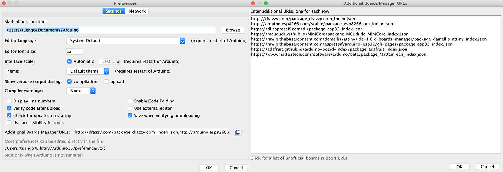
In order to compile the C++ code, the first step was to install the megaTinyCore library which includes Arduino core for the new megaAVR and tinyAVR chips. I navigated to Files > Preferences in Arduino IDE and add board definition URLs (JSON files) to the Add board manager URLs section. Knowing that I might need to try other boards in the future, I added all URLs provided by the instructors (megaTinyCore, ESP32, ESP8266, NodeMCU). And the next step was going to Tools > Board > Boards Manager and installing Arduino AVR Boards, megaTinyCore, esp32, and esp8266 libraries.
Now I had to select the correct ATTiny1614 board. Compiled sucessfully (and pay attention to the path of the generated .hex file in the console)!
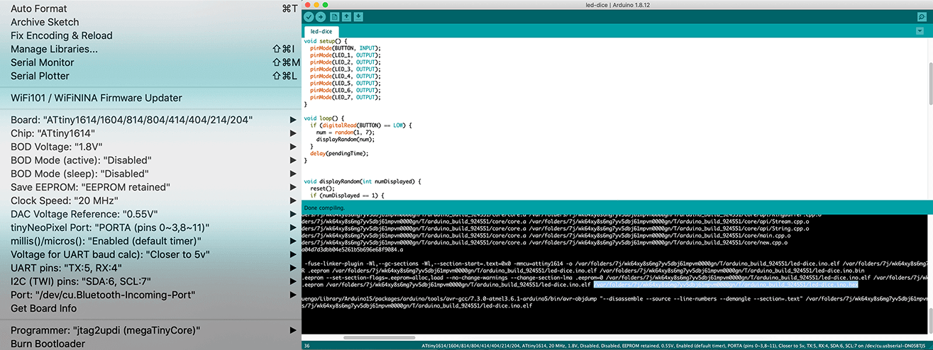
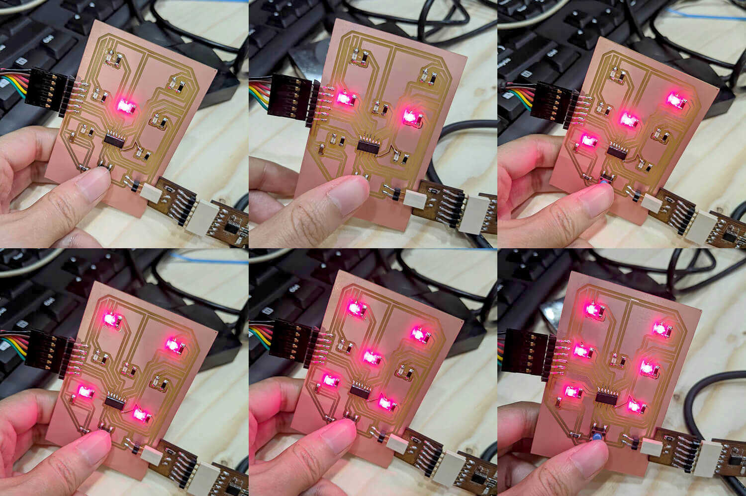
To flash the .hex program to the target board using pyupdi, I need to know the location of the compiled .hex file and the USB port to which my board is connected to. For the first part, I copied the path in the console (see the above image). For the second part, I ran this in Terminal (I was using the computer of my classmate Bruno Molteni with Linux OS since my Mac was running out of battery at the moment) while plugging and unplugging my board: $ dmesg -w. Finally, with ttyUSB0 as the port and /arduino_build_924551/led-dice.ino.hex as the path, I ran this in Terminal: $ pyupdi.py -d tiny1614 -c /dev/ttyUSB0 -b 115200 -f /tmp/arduino_build_924551/led-dice.ino.hex -v. And here you go my working LED dice!
Arduino IDE + Arduino framework + Arduino Uno as programmer + jtag2updi
Since I was not having my FTDI cable with me during the lockdown, I tried to look for another way to program my board without the UPDI programmer (I HATE it by the way). I then bumped into this video tutorial which amazingly taught me how upload my program to the ATtiny1614 board using an Arduino Uno board as UPDI programmer and jtag2updi. jtag2updi can be downloaded by cloning the project $ git clone https://github.com/SpenceKonde/jtag2updi.git. The next step was to open the jtag2updi.ino file in Arduino IDE, and upload it to the Arduino Uno board as a typical Arduino sketch.
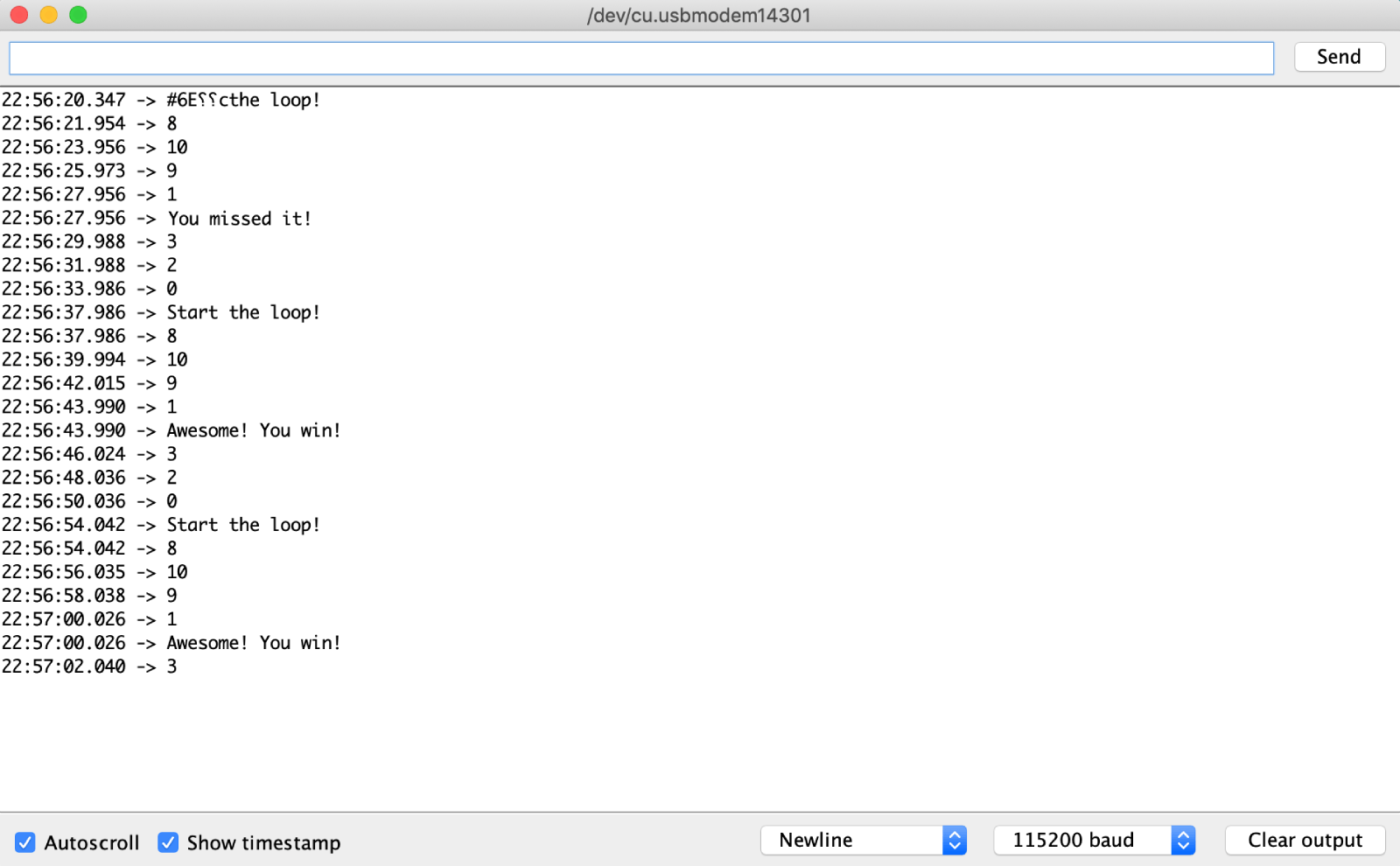
Then I wrote another program for an LED race mini game, simple because I would like to test the built-in Serial Monitor of Arduino IDE. The rule of the game is quite simple: the LEDs will be turned on one after another, and if we press the button at the same time when the LED in the middle is turned on, we win.
    /*
     * assign pins to variables
     */
    int LED_1 = 8;
    int LED_2 = 9;
    int LED_3 = 1;
    int LED_4 = 0;
    int LED_5 = 10;
    int LED_6 = 3;
    int LED_7 = 2;
    int BUTTON = 7;

    /*
     * setup function, to run once
     */
    void setup() {
        pinMode(BUTTON, INPUT);
        pinMode(LED_1, OUTPUT);
        pinMode(LED_2, OUTPUT);
        pinMode(LED_3, OUTPUT);
        pinMode(LED_4, OUTPUT);
        pinMode(LED_5, OUTPUT);
        pinMode(LED_6, OUTPUT);
        pinMode(LED_7, OUTPUT);
        // begin the serial communication with the baud rate of 115200
        Serial.begin(115200);
    }

    /*
     * loop function, to run repeatedly
     */
    void loop() {
        Serial.println("Start the loop!");
        check(LED_1);
        check(LED_5);
        check(LED_2);
        check(LED_3);
        check(LED_6);
        check(LED_7);
        check(LED_4);
        delay(2000);
    }

    /*
     * blink each LED on and check if the button is pressed
     * with the LED pin as the input parameter
     */
    void check(int led) {
        digitalWrite(led, HIGH);
        Serial.println(led);
        if (led == 1) {
            if (digitalRead(BUTTON) == LOW && digitalRead(led) == HIGH) {
                Serial.println("Awesome! You win!");
            }
            else {
                Serial.println("You missed it!");
            }
        }
        delay(200);
        digitalWrite(led, LOW);
    }
The hardware connection was quite simple: the UPDI data pin of the Arduino Uno board is configured to be pin 6 and it needs to be connected to the UPDI pin of ATtiny1614, the ground to the ground, and the 5V pin of Arduino Uno to the VCC pin of ATtiny1614. I actually had a problem with uploading the sketch:
avrdude: jtagmkII_getsync(): timeout/error communicating with programmer (status -1)
Later I found out that I had to add a capacitor 10uF between the RESET and GND pins of the Arduino Uno board in order to disable the reset that is triggered every time we upload a sketch. We also should be careful with the next step while switching from uploading jtag2updi.ino to Arduino Uno to uploading the program led-race.ino to ATtiny1614 board using jtag2updi programmer. I forgot to change the board/programmer several times and then having the same error several times.
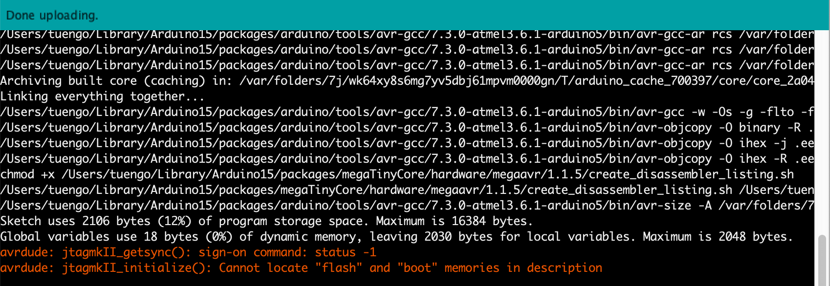
Done uploading! The message below is a spurious warning and can be safely ignored:
avrdude: jtagmkII_initialize(): Cannot locate "flash" and "boot" memories in description
And the LEDs were blinking sequentially!
The game was quite easy though. Here is the sreenshot of what were printed out in the serial monitor (remember to select the correct baud rate by using the same one that was written in the code):
Additional delivery - Program the Arduino Uno board
I would like to try writing programs using plain AVR C and I/O registers, but a whole LED dice seemed to be a bit complex. That's why I only proceeded with programming a simple LED blink and uploading it to the Arduino Uno - ATmega328P board using Make.
Plain AVR C + Make
Make basically uses its $ make command to run the following tools: avr-gcc (compiling and linking source code into a .elf file), avr-objcopy (converting .elf files to .hex), and avrdude (uploading/flashing .hex files to the chip). In order to install that AVR toolchain, I ran these commands in Terminal: $ brew tap osx-cross/avr and $ brew install avr-gcc avrdude.
The next step was to write the C code. Although I know how to code before, I usually code in class-based and object-oriented language, such as Java and C#. This was the first time I used a procedural programming language - the classic C. Since avr-gcc doesn’t know the Arduino Uno board layout, it only knows the micro-controller that is mounted on it which is the ATmega328P, I had to directly use the hardware I/O registers of the ATmega328P chip. Those information can be found in the data sheet. I also explained how to understand the DDR/PORT/PIN registers while reading the above ATtiny1614 datasheet. My C code was written in 3 styles: plain AVR C, using bit masking and using macros. I tried my best to explain the code below:
    /*
     * AVR C libraries
     */
    #include <avr/io.h>
    #include <util/delay.h>
    /*
     * main()
     */
    int main(void) {
        /*
         * the quantity of numbers after 0b are the numbers of PBn pins
         * since we have 6 PBn pins with PB0 as the first pin and PB5 as the last pin
         * then PB5 will be the first number after 0b and PB0 as the last number
         * in this case 0b100000 means setting PB5 as OUTPUT
         */
        DDRB = 0b100000;
        /*
         * similar to loop() in Arduino
         */
        while (1) {
            /*
             * 0b100000 means setting PB5 as HIGH
             */
            PORTB = 0b100000;
            _delay_ms(500);
            /*
             * 0b000000 means setting PB5 as LOW
             */
            PORTB = 0b000000;
            _delay_ms(500);
        }
    }
    #include <avr/io.h>
    #include <util/delay.h>
    /*
     * main()
     */
    int main(void) {
        /*
         * (1 << DDxn) means setting OUTPUT at DDRxn level
         * (0 << DDxn) means setting INPUT at DDRxn level
         * _BV(DDB5) equals (1 << DDB5)
         */
        DDRB |= _BV(DDB5);
        // or DDRB = (1 << DDB5) | DDRB;
        // or DDRB |= (1 << DDB5);
        /*
         * similar to loop() in Arduino
         */
        while (1) {
            /*
             * (1 << PORTxn) means setting HIGH at PINxn level
             * | OR operation
             */
            PORTB |= _BV(PORTB5);
            // or PORTB = (1 << PORTB5) | PORTB;
            // or PORTB |= (1 << PORTB5);
            _delay_ms(500);
            /*
             * (0 << PORTxn) means setting LOW at PINxn level
             * & AND operation
             * ~ NOT operation
             */
            PORTB &= ~_BV(PORTB5);
            // or PORTB = ~ (1 << PORTB5) & PORTB;
            // or PORTB = (0 << PORTB5) | PORTB;
            _delay_ms(500);
        }
    }
    #include <avr/io.h>
    #include <util/delay.h>
    /*
     * Macros
     */
    #define setOutput(directions, pin) (directions |= (1 << pin))
    #define digitalWriteHigh(port, pin) (port |= (1 << pin))
    #define digitalWriteLow(port, pin) (port &= ~(1 << pin))
    #define time_delay() _delay_ms(500)
    /*
     * main()
     */
    int main(void) {
        /*
         * Using macros defined above:
         */
        setOutput(DDRB, DDB5);
        /*
         * similar to loop() in Arduino
         */
        while (1) {
            digitalWriteHigh(PORTB, PORTB5);
            time_delay();
            digitalWriteLow(PORTB, PORTB5);
            time_delay();
        }
    }
The next step was to compile and flash the program to the board using the commands: $ avr-gcc, $ avr-objcopy, and $ avrdude. In order to deal with multiple configurations and commands, I used a Makefile to simplify and automatize the tasks. The $ make command then will read automatically the Makefile and run them. Generally, most of the parameters and options of the avr-gcc and the avrdude tools for the Uno board can be found in the hardware/arduino/boards.txt file within the Arduino IDE installation directory, and some other information are presented in the avrdude manual.
Below is the blink.c.make Makefile I wrote based on Guillem's example:
    /*
     * annotations and variables
     */
    // name of the board
    MCU=atmega328p
    TARGET_ARCH=-mmcu=$(MCU)

    // name of the C file
    TARGET=blink

    // avr-gcc and its parameters/flags
    CC=avr-gcc
    CPPFLAGS=-mmcu=$(MCU)
    CFLAGS=-Os -g -Wall -I. -DF_CPU=16000000
    LDFLAGS=-g -mmcu=$(MCU) -lm -Wl,--gc-sections -Os

    // avrdude and its parameters/flags
    PGMER=-c arduino -p m328p -b 115200 -P /dev/cu.usbmodem14301
    PGMERISP=-c avrispv2 -P /dev/cu.usbmodem14301
    DUDE=/usr/local/bin/avrdude -V -p $(MCU)

    // files with extension
    C_SRCS= $(TARGET).c
    OBJ_FILES= $(C_SRCS:.c=.out)

    /*
     * make commands and related original commands
     */
    all:
        $(TARGET).hex

    clean:
        rm -f $(TARGET).elf *.o *.hex

    %.out: %.c
        $(CC) -c $(CPPFLAGS) $(CFLAGS) $< -o $@

    $(TARGET).elf: $(OBJ_FILES)

        $(CC) $(LDFLAGS) -o $@ $(OBJ_FILES)
    $(TARGET).hex: $(TARGET).elf
        avr-objcopy -j .text -j .data -O ihex $(TARGET).elf $(TARGET).hex
        avr-objcopy -j .eeprom --set-section-flags=.eeprom="alloc,load" --change-section-lma .eeprom=0 -O ihex $(TARGET).elf eeprom.hex

    upload: $(TARGET).hex
        $(DUDE) $(PGMER) -U flash:w:$(TARGET).hex

    size: $(TARGET).elf
        avr-size --format=avr --mcu=$(MCU) $(TARGET).elf
I ran all the commands separately and took a look at the logs to see how Make used the Makefile to compile, link, and flash the program to the chip. At each step, a new file (blink.out, blink.elf, or blink.hex) was generated respectively. The last command uploaded the .hex file to the chip.
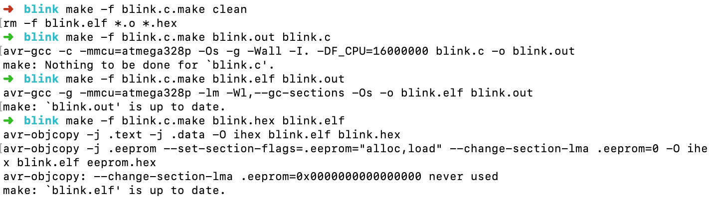
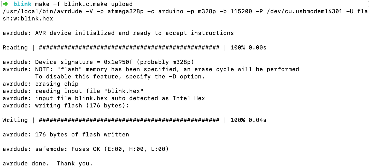
The LED blinked on and off as expected!
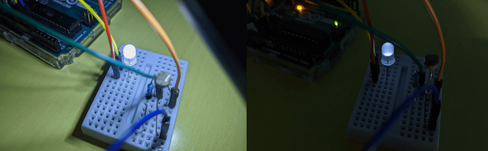
Let's do something a bit more complicated. I intended to write a simple AVR C program with which the LED fades based on LDR analog value. I followed some AVR C examples (here and here) in order to know how to analogRead() an LDR and analogWrite() an LED. In short, I had to work with ADC register and conversion, Timer/Counter interrupt handler, PWM mode, and duty cycle.
And below is the C code:
    #include <avr/io.h>
    #include <util/delay.h>

    /*
     * main() function, by default returns 0
     */
    int main (void) {
        // setup ADC
        initialize_ADC();
        // setup PWM
        initialize_PWM();

        // initial brightness, duty cycle = 0%
        uint8_t brightness = 0;
        // store LDR readings as volatile data
        volatile uint8_t adc;

        /*
         * loop() function
         */
        while (1) {
            // divide the reading by 8 and use the result as input duty cycle
            set_PWM(read_ADC()/8);
            _delay_ms(5);
        }
        return 0;
    }
    /*
     * initialize ADC pin and mode
     */
    void initialize_ADC() {
        // set pin PC0 as INPUT and select ADC(0) as ADC channel
        DDRC |= (1 << PC0);
        ADMUX = 0;

        // use AVCC as the reference, and adjust for 8 bit resolution
        ADMUX |= (1 << REFS0) | (1 << ADLAR);

        // set prescaler to clock/128 and enable ADC
        ADCSRA |= (1 << ADPS2) | (1 << ADPS1) | (1 << ADPS0) | (1 << ADEN);
    }

    /*
     * read and return the LDR
     */
    int read_ADC() {
        int ADCval;
        // start the ADC conversion
        ADCSRA |= (1 << ADSC);
        // wait for the ADC to finish
        while (ADCSRA & (1 << ADSC));
        ADCval = ADCL;
        // update reading
        ADCval = (ADCH << 8) + ADCval;
        // return reading
        return ADCval;
    }

    /*
     * initialize PWM pin and mode
     */
    void initialize_PWM() {
        // set pin PD6 (pin 6~) as OUTPUT
        DDRD |= (1 << PD6);
        // use timer0, activate fast PWM mode and non-inverting mode
        TCCR0A |= (1 << WGM00) | (1 << WGM01) | (1 << COM0A1);
        // set prescaler to clock/8 and start PWM
        TCCR0B |= (1 << CS01);
    }

    /*
     * use the input duty cycle to control the brightness of the LED
     */
    void set_PWM(uint8_t duty) {
        OCR0A = duty;
    }
I used the same Makefile and followed the same process to flash the program to the Arduino Uno board (remember to change all file names from blink to fade). Ta-dah! The fading was not really smooth, but my code worked as expected!
Additional delivery - Program the ESP32-WROOM Barduino 2.0
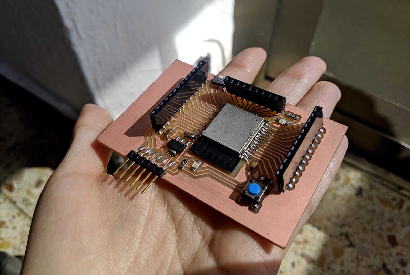
Barduino 2.0 is an ESP32 compatible board designed by our instructor Eduardo Chamorro, and during the last day of the lab before the lockdown, we had a chance to quickly fabricate it. I'd like to play around with the Barduino board in order to try other programming frameworks, especially ESP-IDF and MicroPython.
Arduino IDE + Arduino framework
In order to test whether the Barduino board worked, I tried a simple blink program written and compiled using Arduino IDE. As shown in the pinout diagram, the built-in LED is connected to the GPIO-13 pin.
Below is the classic blink program:
    #define BUILTIN_LED 13
    void setup() {
        pinMode(BUILTIN_LED, OUTPUT);
    }
    void loop() {
        digitalWrite(BUILTIN_LED, LOW);
        delay(1000);
        digitalWrite(BUILTIN_LED, HIGH);
        delay(1000);
    }
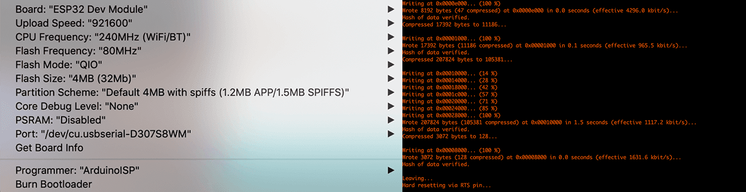
The process was exactly the same as my LED dice, except for choosing the ESP32 Dev Module as the board, /dev/cu.usbserial-D307S8WM as the port (I was using my Mac at the moment). The interesting thing about ESP32 boards is that I don't need an external programmer, since the ESP32 will enter the serial bootloader when GPIO0 is held low on reset, otherwise, it will run the program in flash. Many boards use a button marked "Flash" or "Boot" that pulls GPIO0 low when pressed. In the case of the Barduino board, we have a programmer slider switch that changes the mode of the chip: programming mode or normal execution mode. This is indeed very important since I had to switch on the programming mode and keep pressing the reset button during the flashing process in order to upload my program. Otherwise, I would have the below error:
A fatal error occurred: Failed to connect to ESP32: Timed out waiting for packet header
And it worked as expected! Good soldering!
Proof of a working board:
PlatformIO + ESP-IDF framework
PlatformIO is a cross-platform, cross-architecture and multiple framework tool for embedded programming. I personally prefer PlatformIO to Arduino IDE since it works effectively in Terminal (they have an IDE, but I simply used vim as the editor and directly used the command lines). Besides, PlatformIO offers integrated libraries for a wide range of boards and frameworks, including Arduino framework and ESP-IDF framework. Thanks to PlatformIO, I didn't have to go through all the complicated setup and configuration steps. All that I had to do to set up the ESP-IDF development environment was:
- $ brew install platformio: install PlatformIO
- $ mkdir barduino-blink-platformio and $ cd barduino-blink-platformio: create a folder for my project and go inside the folder (meh)
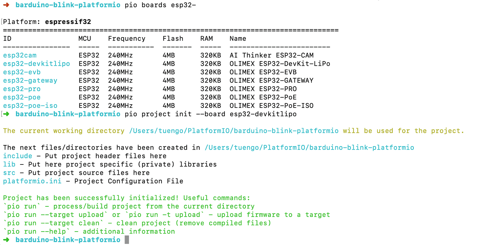
- $ pio boards esp32-: browse the libraries and look for the ESP32 board. Here I saw many boards, and the esp32-devkitlipo seemed to be the one I was looking for.
- $ pio project init --board esp32-devkitlipo: initialize the project. Now if I run $ ls I would see a typical ESP-IDF structure with an
empty.cfile andplatformio.inifile (all that I should care about unless I want to rename the C file).
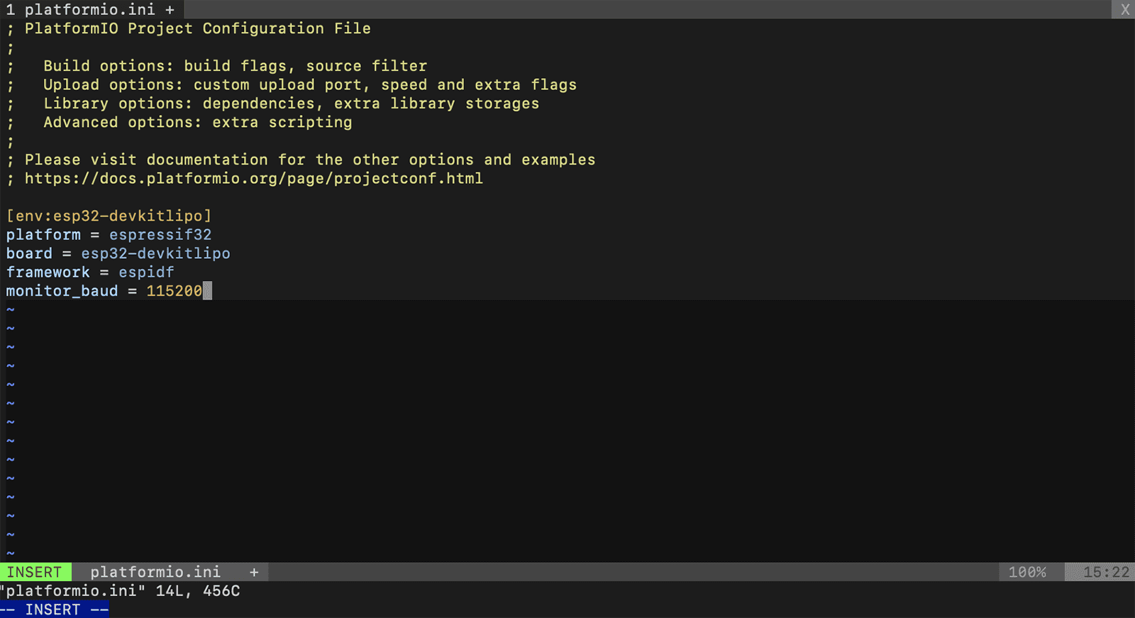
The next step was to put some configurations into the platformio.ini file. I haven't read about it carefully, but the baud rate 115200 was recommended by many tutorials.
And below is the C code to put into the empty.c file, with some not-so-useful comments (yes you're right, I'm the type of developer that can comment something like /* Lorem ipsum dolor sit amet */):
    /*
     * C libraries
     */
    // define several macros and various functions for performing input and output
    #include <stdio.h>
    // FreeRTOS is a real-time operating system kernel for embedded devices
    #include <freertos/FreeRTOS.h>
    #include <freertos/task.h>
    // ESP-IDF driver used to setup/configure GPIO's mode, interupt trigger type, and many more...
    #include <driver/gpio.h>
    // auto-generated ESP-IDF config file containing saved settings
    #include <sdkconfig.h>

    /*
     * assign pins to variables
     */
    #define BLINK_GPIO 13

    void app_main(void){
        gpio_pad_select_gpio(BLINK_GPIO);
        /*
         * set the GPIO as an output - similar to setup() in Arduino
         */
        gpio_set_direction(BLINK_GPIO, GPIO_MODE_OUTPUT);
        /*
         * similar to loop() in Arduino
         */
        while(1) {
            gpio_set_level(BLINK_GPIO, 0);
            /*
             * FreeRTOS function to specify a time
             * at which the task wishes to unblock relative to
             * the time at which vTaskDelay() is called
             */
            vTaskDelay(1000/portTICK_PERIOD_MS);
            gpio_set_level(BLINK_GPIO, 1);
            vTaskDelay(1000/portTICK_PERIOD_MS);
        }
    }
In order to compile and flash the program to the chip, these commands were executed:
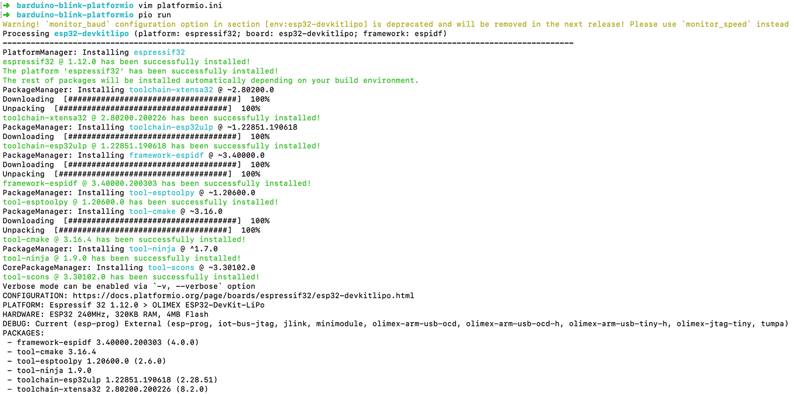
- $ pio run: compile the C source code. In order to understand what was going on behind the scenes, I analyzed the log a bit. Basically, by running $ pio run, PlatformIO helps us to install and run some useful tools: esp-idf framework, toolchain-xtensa32 (ESP32 toolchain to compile code), CMake and Ninja (build systems similar to Make), and esptool.py (flashing utility similar to pyupdi).
- $ pio run -t upload: flash the program to the chip using esptool.py commands
The LED blinked on and off again, but it's unnecessary to keep posting another video with the same content ;)
MicroPython + esptool.py + ampy
MicroPython is an open-source Python interpreter that runs on small embedded development boards. With MicroPython we can write easy-to-read Python code instead of having to use brain-tangled languages like C/C++ (I don't know why many people consider Python as simpler than C++, to me they're quite the same). Actually, the nice thing about MicroPython is that it has an interactive REPL feature which is a simple computer programming environment that takes single user inputs, evaluates them piecewise, and returns the result to the user. I definitely had to try MicroPython, since they said using MicroPython is a great way to get the most of an ESP32 board, and vice versa, the ESP32 chip is a great platform for using MicroPython.
To use MicroPython, the first thing was to download the most recent MicroPython firmware .bin file which would be loaded onto the ESP32 board. I followed this tutorial and downloaded the firmware here.
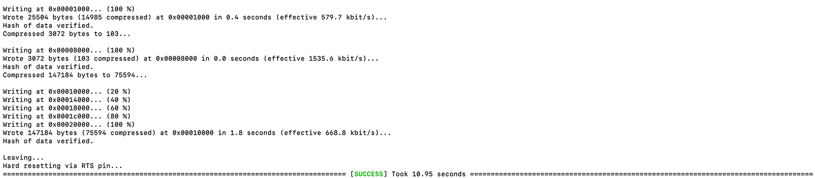
It is recommended to first erase the entire flash of the ESP32 board before putting on the new MicroPython firmware. To do that, first I had to install esptool.py by running $ pip install esptool in Terminal. Then these commands were executed:
- $ esptool.py --port /dev/cu.usbserial-D307S8WM erase_flash: erase the entire flash
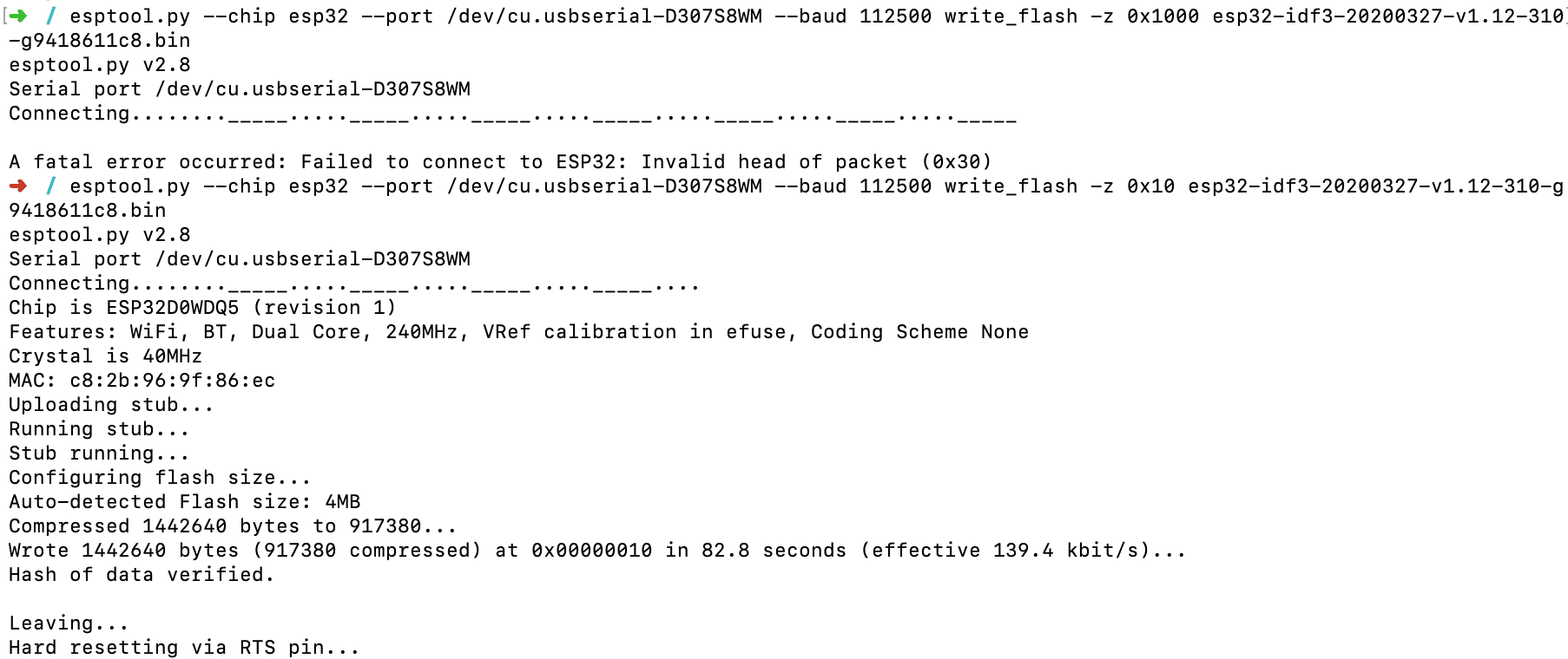
- $ esptool.py --chip esp32 --port /dev/cu.usbserial-D307S8WM --baud 112500 write_flash -z 0x10 esp32-idf3-20200327-v1.12-310-g9418611c8.bin: deploy the new firmware
Actually I had an error trying to deploy the firmware while following the exact command line mentioned in the tutorial $ esptool.py --chip esp32 --port /dev/cu.usbserial-D307S8WM --baud 112500 write_flash -z 0x1000 esp32-idf3-20200327-v1.12-310-g9418611c8.bin:
A fatal error occurred: Failed to connect to ESP32: Invalid head of packet (0x30)
After checking carefully again, I assumed the problem was not the port or the firmware's path, and after bumping into this section, I found out that I should use the correct address of the GPIO0 pin, which is 0x10 instead of 0x1000. And the MicroPython firmware was successfully deployed!
Below is the Python code I wrote in a new main.py file.
    // control GPIO pins
    import machine
    // give access to underlying interpreter values
    import sys
    // tell the program to wait for a specified amount of time
    import time

    /*
     * similar to setup() in Arduino
     */
    led = machine.Pin(13, machine.Pin.OUT)

    /*
     * similar to loop() in Arduino
     */
    while True:
        // print something to debug in the serial monitor
        print("LED ON")
        led.value(1)
        time.sleep(0.5)
        print("LED OFF")
        led.value(0)
        time.sleep(0.5)
MicroPython is a little different at first glance compared to all of the above workflows. With MicroPython, the language may have come with the hardware, and we have the option of working with it interactively via its REPL (read-evaluate-print-loop) feature. For most MicroPython boards, we can access the MicroPython REPL over USB serial connection or Wifi. To get a serial REPL on a Mac, I entered the built-in serial terminal and connect to the board by running: $ screen /dev/cu.usbserial-D307S8WM 115200.
In order to upload the main.py program to ESP32 chips, I used a tool called ampy, which is a Python script that can read and write files to a MicroPython board over a serial connection. I followed this tutorial and ran $ pip install adafruit-ampy to install ampy.
At this point I faced 2 problems:
- I couldn't see >>> prompt while entering the serial terminal. After pressing Control-C a couple times to interrupt any running program on the board, it still didn't work.
- All ampy commands took forever to execute. I tried running $ ampy --port /dev/cu.usbserial-D307S8WM ls to list the available files, $ ampy --port /dev/cu.usbserial-D307S8WM get boot.py to read the
boot.pyconfig file, and $ ampy --port /dev/cu.usbserial-D307S8WM put main.py to upload themain.pyblink program to the chip. Both commands took a long time without finishing execution or returning any errors.
After researching for a while, I noticed that ampy is no longer maintained by Adafruit which is a piece of bad news for my previous attempts since issues will no longer be solved. The biggest downside of MicroPython could be a small community where there are only a few example codes or questions solved online. I assumed that the problem could be because I didn't enter the programming mode of the board correctly, but, losing motivation, I decided to leave it like that for this week. I might get back to MicroPython in the future, but for now I'm pretty sure I will continue using Arduino or ESP-IDF for upcoming assignments.
Group assignment - Compare tinyAVR, megaAVR and Xtensa families
Or should I call it the TL,DR; section?
Comparing the micro-controllers
Due to the COVID-19 lockdown, I couldn't work with my classmates for the group assignment. Hence, again, I tried to fulfill it myself by comparing my experiences reading the data sheets and programming the ATtiny1614, ATmega328P and ESP32-WROOM boards (we classmates were working with similar MCUs anyway).
| MCU - MCU family | Working voltage | Flash memory | EEPROM | RAM | GPIO pins | ADC | DAC | PWM | Serial protocol | Wireless communication | Programming protocol/interface | External programmer required |
|---|---|---|---|---|---|---|---|---|---|---|---|---|
| ATtiny1614 - Atmel tinyAVR | 1.8 - 5.5V | 16 kiB | 256 bytes | 2 kiB | 11 usable | 10 channels | Yes | 5 channels | UART, SPI, I2C | No | UPDI | Yes |
| ATmega328P - Atmel megaAVR | 1.8 - 5.5V | 32 KiB | 1 KiB | 2 kiB | 23 usable | 8 channels | No | 6 channels | UART, SPI, I2C | No | AVRISP, ArduinoUSP, USBasp | Yes (in general) - No (in case of Arduino Uno board) |
| ESP32-WROOM - Xtensa ESP32 | 2.3 - 3.6V | 16 MB | 512 bytes | 520 KiB | 34 usable | 18 channels | Yes | 16 channels | SPI, UART, I2C, I2S, SDIO, Ethernet | Wifi, Bluetooth, IR, RF | UART bootloader, OTA | No |
Comparing development workflows
To make this part more like a "group" assignment, I included here the development workflows that my classmates went through in addition to what I did. All of them tried many workflows and made amazing programs, but I limited the list to workflows that are different from mine.
| MCU | Student | Editor/IDE/IDP | Language | Framework | Configuration file | Compiler/Linker | Flashing tool/utility | Hardware ISP | Serial monitor |
|---|---|---|---|---|---|---|---|---|---|
| ATtiny1614 | Myself | Arduino IDE | C++ | Arduino | No | avr-gcc + ld (Arduino IDE) | pyupdi | UPDI adapter | Arduino IDE's Serial Monitor |
| ATtiny1614 | Myself | Arduino IDE | C++ | Arduino | No | avr-gcc + ld (Arduino IDE) | avrdude (Arduino IDE) + jtag2updi | Arduino Uno | Arduino IDE's Serial Monitor |
| ATmega328P (Arduino Uno) | Myself | vim | C | No | Makefile | avr-gcc + arv-objcopy (GNU Make) | avrdude (GNU Make) | No | Mac OS X's screen |
| ESP32-WROOM | Myself | MicroPython's REPL + vim | Python | No | boot.py |
MicroPython | esptool.py + ampy | No | Mac OS X's screen |
| ESP32-WROOM | Myself | PlatformIO + vim | C | ESP-IDF | platformio.ini and CMakeLists.txt |
CMake + Ninja (PlatformIO) | esptool.py (PlatformIO) | No | PlatformIO's Miniterm-based serial monitor |
| ESP32-WROOM | Benjamin Scott | GNU nano | C | ESP-IDF | CMakeLists.txt |
CMake + Ninja (idf.py) | esptool.py (idf.py) | No | IDF Monitor |
| ATSAMD21 (Circuit Playground Express) | Antoine Jaunard | PlatformIO + Neovim | C++ | Arduino | platformio.ini |
gcc-arm-embedded (PlatformIO) | SAM-BA (PlatformIO) | No | PlatformIO's Miniterm-based serial monitor |
Conclusion
In general, it was a hardcore but fun week and I understood better some terms and concepts I heard before. I really enjoyed working with the ESP32 micro-controller, and its ESP8266 predecessor seems to be good too. They're cheap, they have many GPIO pins, and they don't need an external ISP in order to be programmed. Something similar to the Arduino Uno board could also be a good choice. PlatformIO is also really amazing! It supports many boards and platforms, includes many toolchains and frameworks. In case I need help from the active Arduino communities, I can easily refer to similar issues and apply solutions using PlatformIO. It also has a very stable Miniterm-based built-in serial monitor, which is much better than Arduino IDE's Serial Monitor and Mac OS X's screen. The workflow was also simple and straightforward, and I can do everything using command lines. I will definitely use PlatformIO and Xtensa chips for upcoming assignments!