This week's assignment is to test run-out, alignment, speeds, feeds, and toolpaths of the CNC machine (in-group); to make something big (individual).
* All G-CODE, STL, and original editable files can be downloaded here.
* This week's group assignment is to test the feeds, speeds, and toolpaths of the CNC machine with a chosen material.
* I need to individually design, mill, and assemble something big.
CNC machining
Due to the COVID-19 pandemic, we had to confine ourselves at home right after the global class and couldn't get access to the machines by any means. Hence, my plan was to go ahead with designing the individual assignment first and prepare all possible CAM files, then when we can go back to the lab we should be ready to test, fabricate and assemble.
Group assignment - Characterize the CNC machine
Generating toolpaths with RhinoCAM
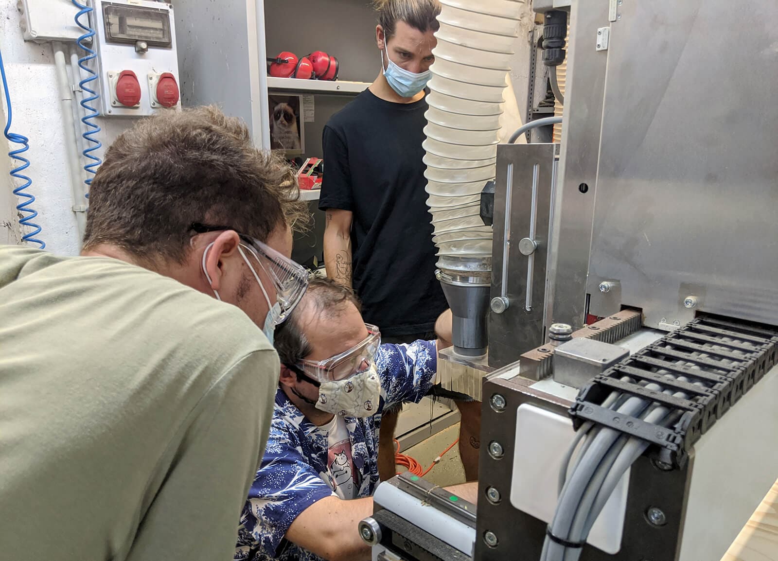
This part was done after we got back to Fab Lab Barcelona. Although it was not easy to gather people after the lockdown, I had a chance to team up with my classmates Arman Naraji, David Prieto, Antoine Jaunard, and Lynn Dika for this group assignment.
The CAM file of the test was done in RhinoCAM. I myself documented the detailed steps below in the individual assignment, but here you go some of them:
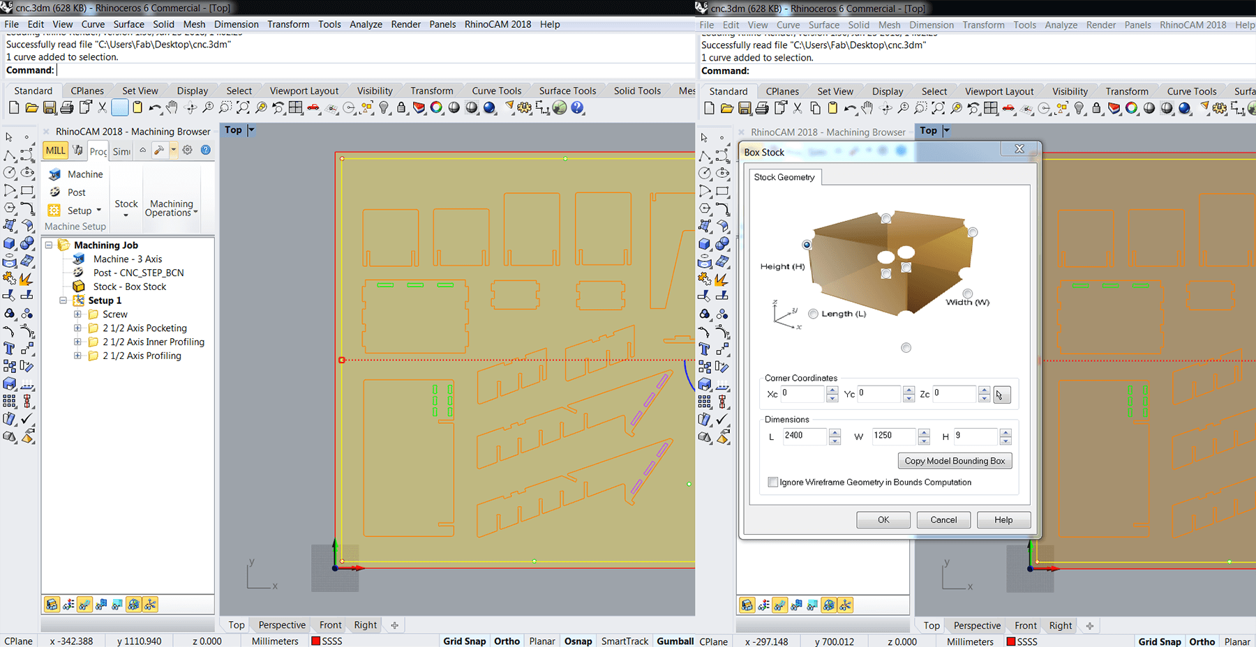
- Navigate to Stock > Box Stock, select the stock object (2,400 x 1,250 x 9mm rectangle) and select the right X0,Y0,Z0 (left-bottom-upper point of the stock)
- Create an inner offset of around 20mm and create multiple points along the offset line. These marks would be drilled to mark the screw locations.
- Create a 1-flute new Flat-end Mill 6mm with below details:
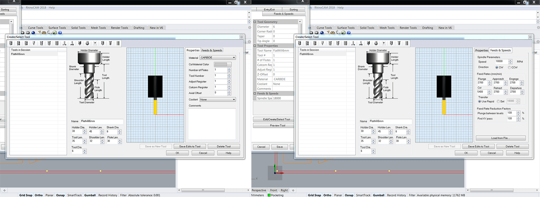
The formula used to calculate the tool's feed and speed is: Feed rate = N x CPT x RPM, with feed rate as the speed at which the cutter engages the part, N as the number of flutes (the sharp slots that corkscrew upwards along the length of a milling bit), CPT as the chip load (the thickness of material removed by each cutting edge during a cut), and RPM as the spindle speed at which the spindle of the machine rotates. We checked the chipload for plywood here and the calculation tool gave us a range of 0.28 - 0.33. Hence, the first cutting feed rate we put in the Feed & Speed tab was 1 flute x 0.3mm x 18,000rpm = 5,400mm/min. Other feed rates were set around 2,700mm/min which is half of the cutting feed rate. We then used these feed rates for the tolerance test.
Next, we created a Machining Operation > Engraving strategy for the screw marks and Machining Operation > 2-axis Profiling strategy for the pieces. Remember to put 30mm in Clearance Plane > Stock Max Z + Distance for the screw marks. This would help to prevent the tool from crashing with the bent material while traveling.
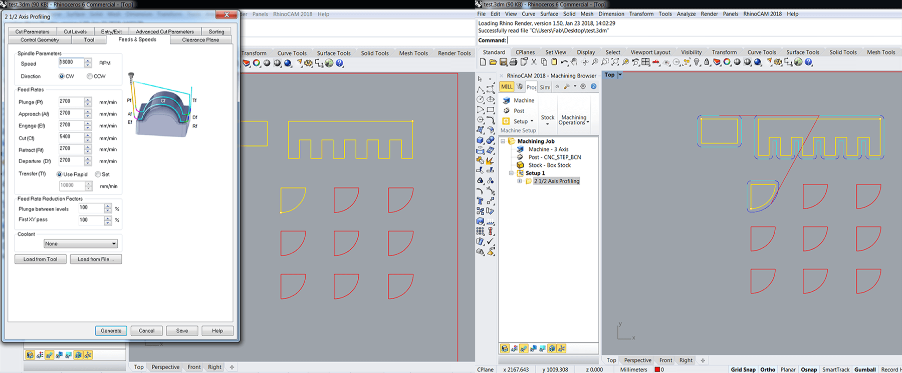
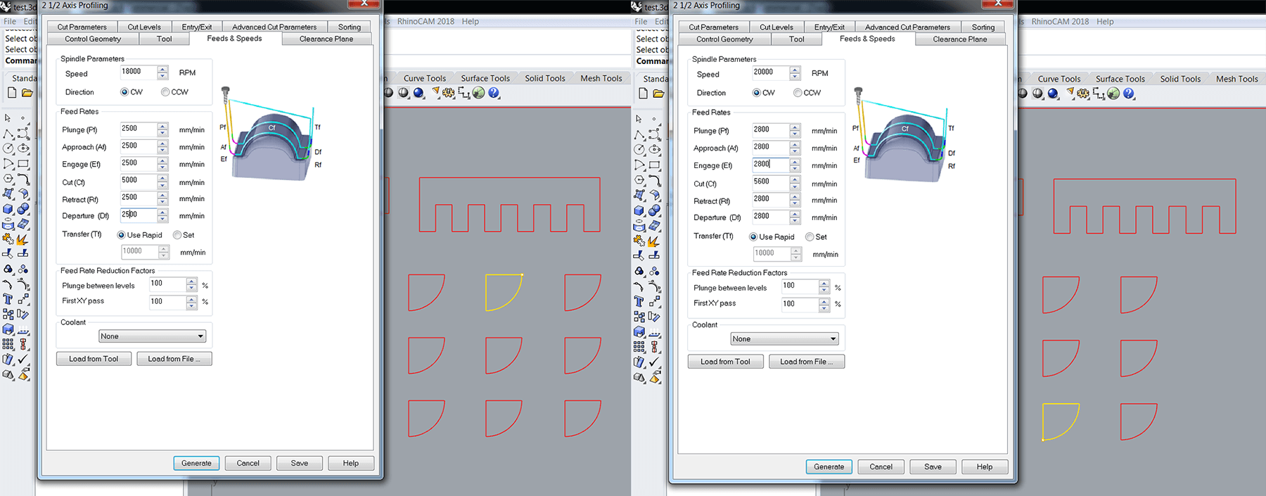
Now it's time to play with the spindle speed and the feed rates as per the requirements of the assignment. We used the same formula and created these operations:
- 1 flute x 0.28mm x 18,000rpm = 5,000mm/min
- 1 flute x 0.3mm x 18,000rpm = 5,400mm/min
- 1 flute x 0.33mm x 18,000rpm = 5,900mm/min
- 1 flute x 0.28mm x 20,000rpm = 5,600mm/min
- 1 flute x 0.3mm x 20,000rpm = 6,000mm/min
- 1 flute x 0.33mm x 20,000rpm = 6,600mm/min
The last step was to Post these operations to the CNC_STEP_BCN processor as a .nc file. Ready to go!
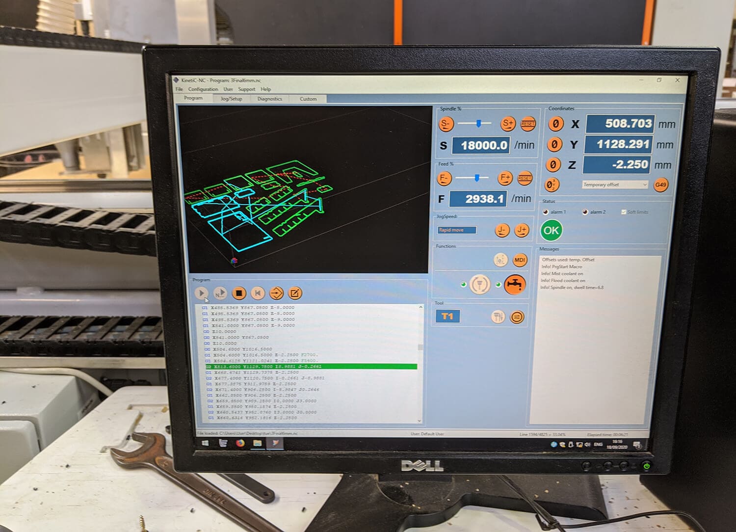
Machining with RaptorX-SL
We used the Raptor X-SL 3200/S20 machine and its software KinetiC-NC to do the test. The detailed specs of the machine:
- Working area: 3,200 x 2,010 x 300mm
- Clamping area: X -3,500mm x Y -2,200mm
- Positioning speed X+Y/Z: maximum 40,000mm/min
- Working speed: maximum 20,000mm/min
- Step width X: 0.0213mm
- Step width Y+Z: 0.0113mm
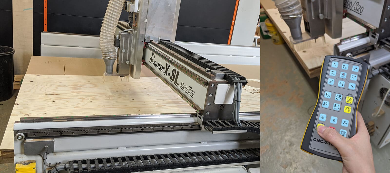
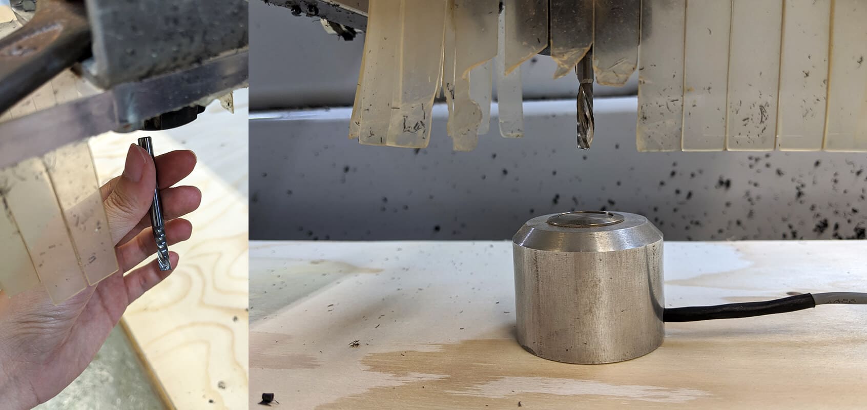
Mikel guided us through the whole process. Before launching the .nc file, we used the machine’s wrench and key to release the collet and holder, and put on the climb (cut down) 6mm flat-end mill. Then we needed to find a good Z0 by using a button-like Z0 finder.
After running the toolpath of the screw marks, screwing the stock, and running the toolpath of the cut pieces, we got the test result. The tolerance test starts with tolearnce=0.1mm, 0.2mm, 0.3mm, 0.4mm, and 0.5mm.
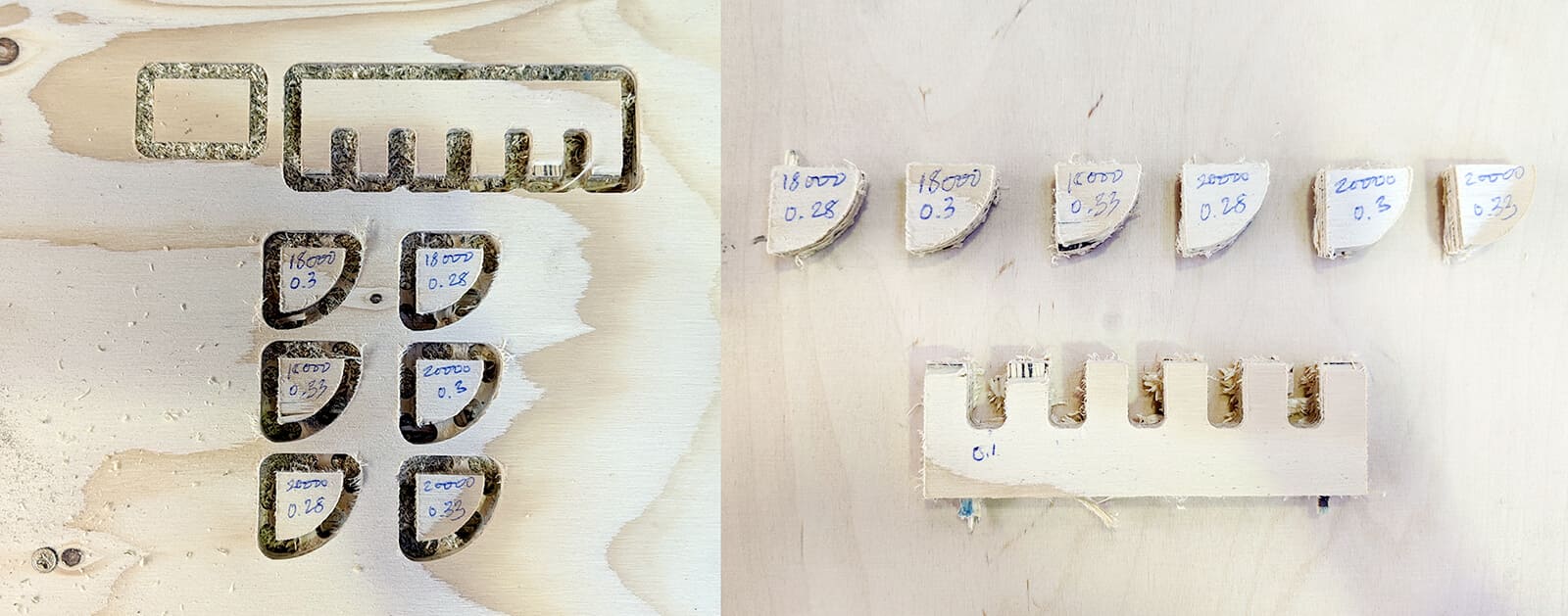
When the machine performed the 2 last cuts, we could hear an annoying sound like a baby crying for breast-feeding. This helped me to confirm that we should never play with a feed rate above 6,000mm/min. Also, I personally find the feed rate of 5,400mm/min and the spindle speed of 18,000RPM to be the most satisfying settings. As for tolerance measurement, 0.3-0.4mm will be the perfect one for a tight fit.
What I personally learned:
- Safety first: wear safety glasses and earbuds!
- It is important to measure the full stock from every corner since the material will never be exactly 9mm or 15mmm, also different parts can have different thicknesses due to fabrication or storage conditions
- The 0 position of the machine is set by default to the left-bottom-upper point of the stock and the X axis is always the longer side of the stock
- Be really careful with the screws: when they're fucked up, it will be annoyingly difficult to handle them
- Math does not lie: we should never play with a feed rate above 6,000mm/min, else the baby will cry!
- We should take it slowly and carefully while breaking the tabs and removing the pieces since the piece removal can harm the final pieces and create splinters on the visible parts of the final result
- KNOW WHERE THE EMERGENCY STOP BUTTON IS!
- TURN ON THE AIR VENTILATION!
- MEASURE THE MATERIAL AND RUN A TOLERANCE TEST BEFORE FINALIZING THE DESIGN!
Individual assignment - Make something big
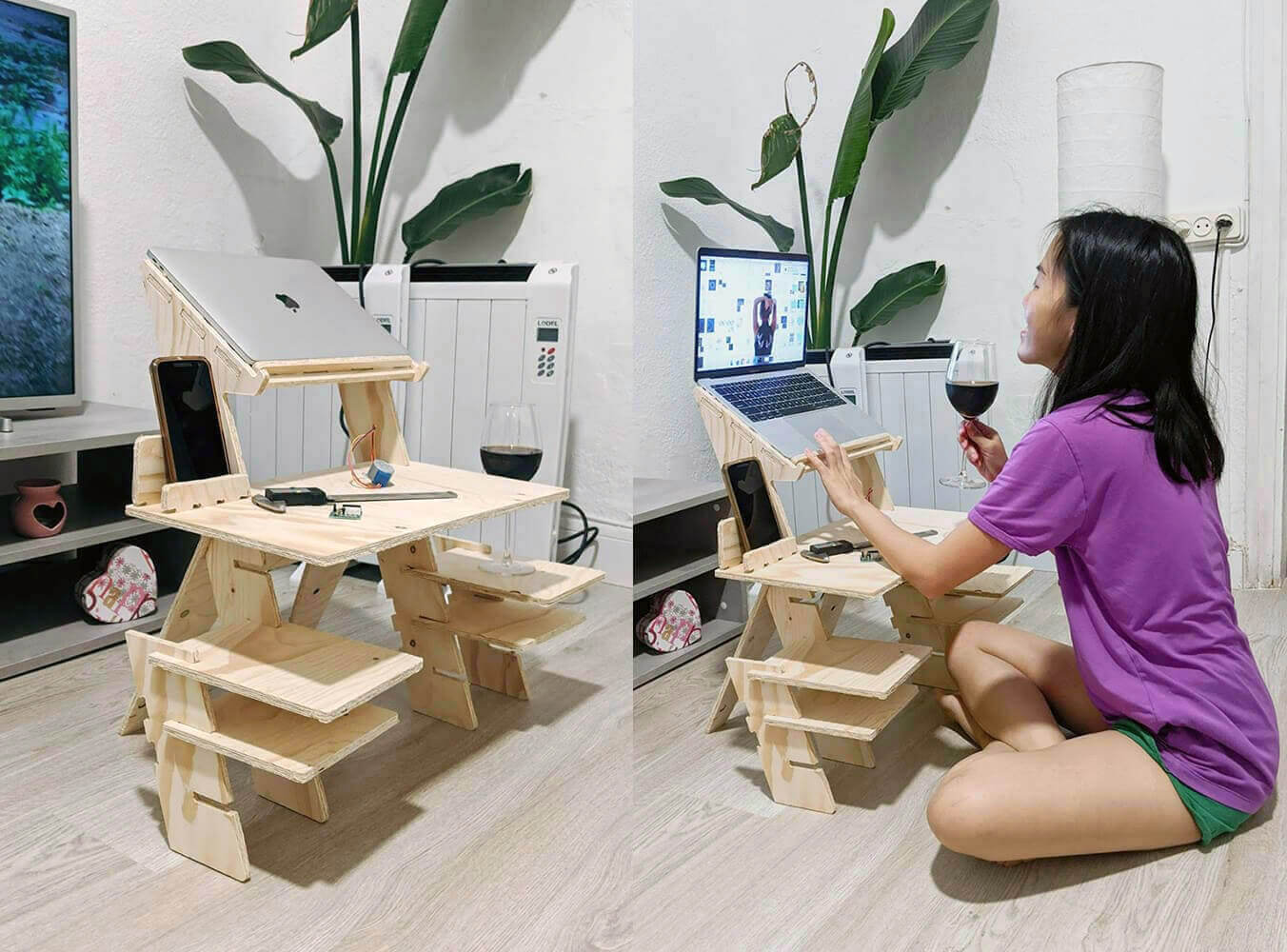
This part was designed during the COVID-19 lockdown. I had to work at home quite a lot during the lockdown, and sometimes I was in the mood of working on the balcony, in the kitchen, or even while lying down on my bed. It was really inconvenient to carry my laptop and all other pieces of stuff (phone, mouse, cables, boards, electronic components, etc.) around. Hence, I decided to design a 560 x 580 x 300mm portable desk using Fusion 360. RhinoCAM and Aspire CAM were introduced by the instructors, however, after researching online, I learned that I can generate toolpaths for ShopBot using Fusion 360. So, why not?
Designing with Fusion 360
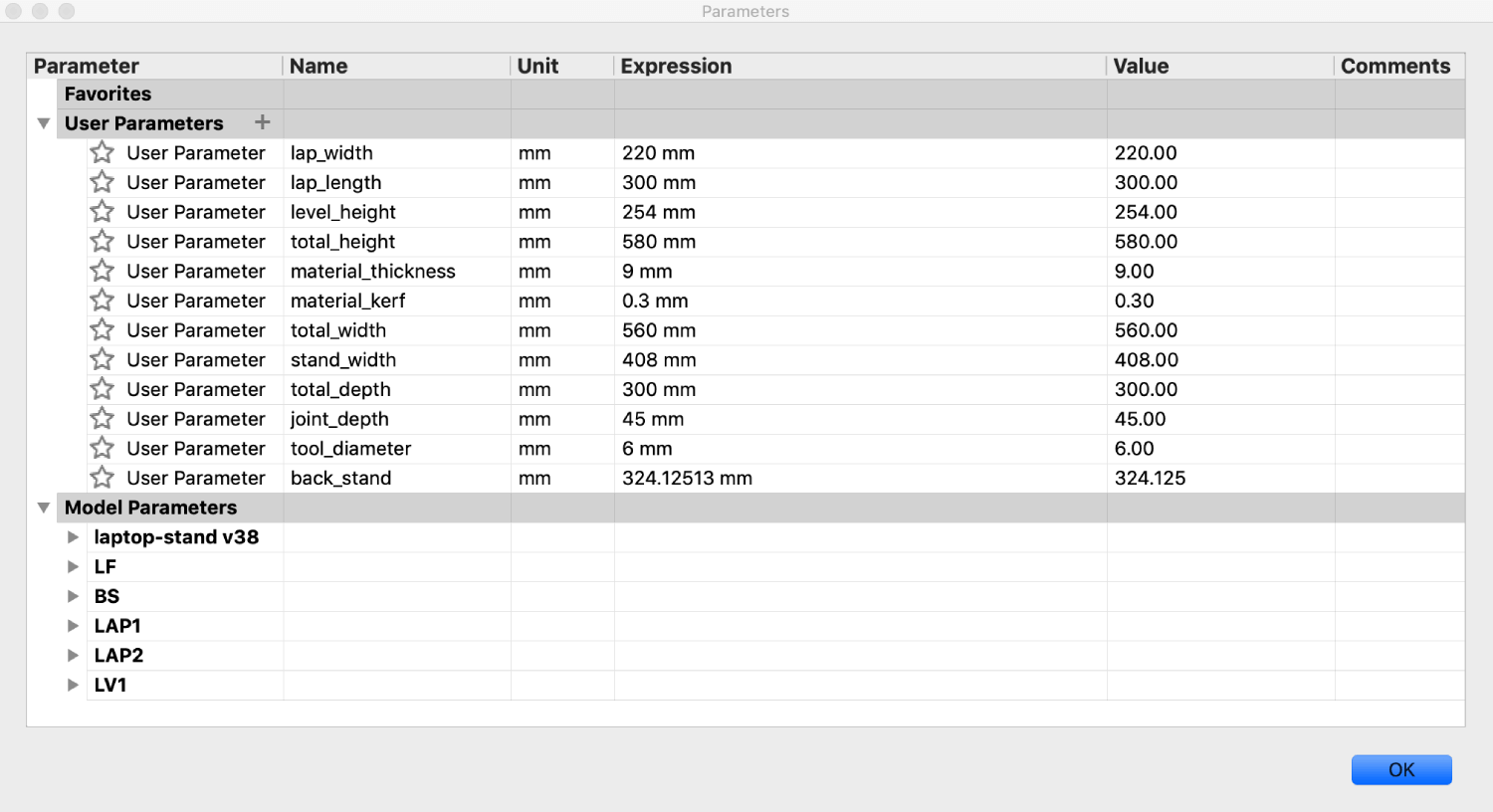
Now I can follow the UNFOLDING design process which I couldn't do properly during the 4th week. The very first thing I need to know was the stock size and the thickness of available materials at Fab Lab Barcelona. Since measuring materials and doing a press-fit test was impossible during the social distancing, I had to talk to Josep and also took a look at the alumni's websites. Based on gathered information (2,400 x 1,250mm plywood, 9mm and 15mm thickness, 0.2 - 0.3mm tolerance, 6mm end mill), I assumed some below parameters (which might be modified after I get access to the lab):
The next step was to plan the possible joints. Some useful references for CNC-able joints: the classic 50 Digital Wood Joint and this SATISFYING collection of Japanese-styled joinery. I tried to apply many types of joinery in my design, but some joints I'd like to try (such as tongue and groove, tenon and mortise, dovetails, etc.) could not be done since we are limited to only perform one-sided cuts. Therefore, I could only include simple slotting joints and finger joints.
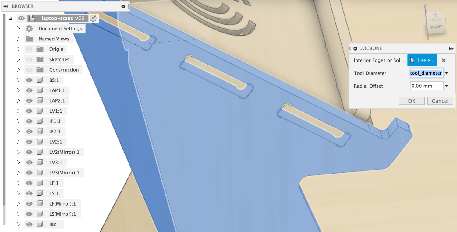
Next, I had to create dogbones which are additional interior corner cuts for removing more material in the CNC process in order to clear out the interfering corner (the result of cutting material using a round-shaped tool). In order to add dogbone fillets to the joints, I installed this Fusion 360 add-in. Basically, the add-in helped me performing 3 tasks at once: creating a Plane Along Path from an edge, create a sketch (supposedly the edge itself), and Sweep it with the same diameter as the tool diameter (6mm).
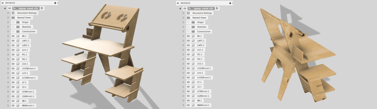
This is how my portable desk should look like after being fully assembled. Here I have an integrated Macbook holder, adjustable trays (where I can put my mouse, my keyboard, my touchpad, working PCBs, etc.), phone holder, and assemblable drawers (storing electronic components, cables, and other tools):
Here you go the 3D model on Sketchfab, ready to be unfolded!
I felt quite confident with the 0.3mm tolerance even before we could get back to the lab to do the test, so I went ahead with it. NOTE: tolerance=0.3mm means to allow an offset of 0.15mm from each side to make a perfect fit.
Generating toolpaths with Fusion 360
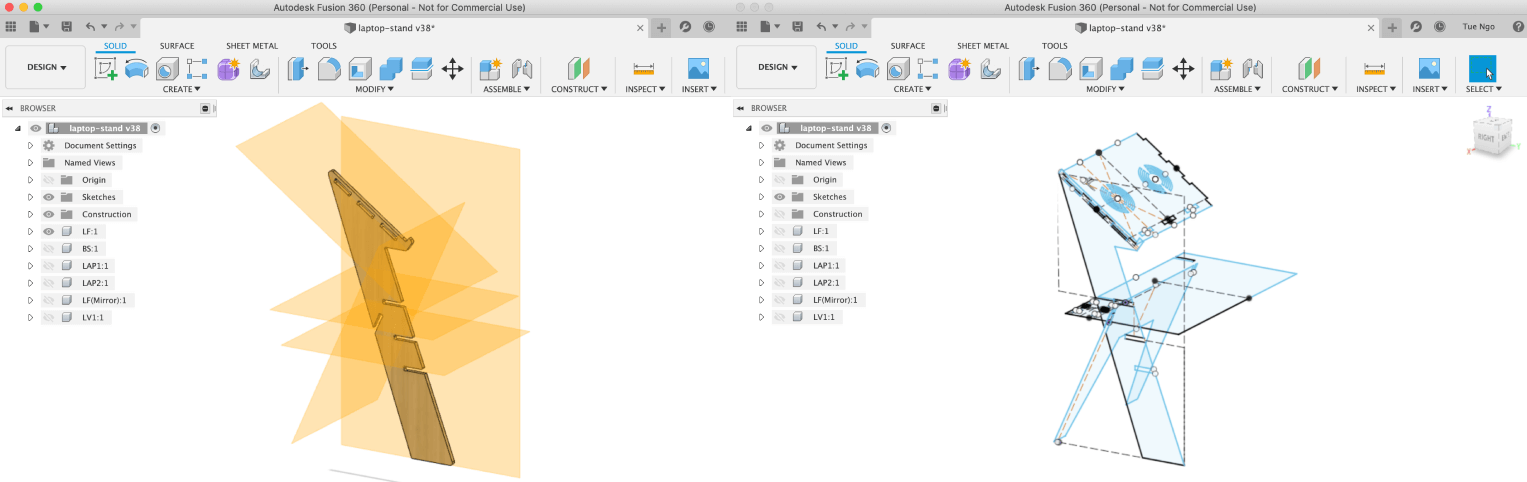
In order to avoid wasting time during the social distancing, I decided to continue with the process of preparing CAM files before testing the stability and press-fit clearance (FINGER-CROSSED). It's good to go through the process once anyway, and if I'm lucky, I won't need to re-design everything. I found great documentation from Krisjanis Rijnieks (Fab Lab Barcelona 2018) where he described in detail the whole process of using Fusion 360 to prepare files for manufacturing on a ShopBot. Before switching from the Design environment to the Manufacture environment, I had to unfold all pieces in my design and align them onto the stock.
Some steps followed to unfold the portable desk:
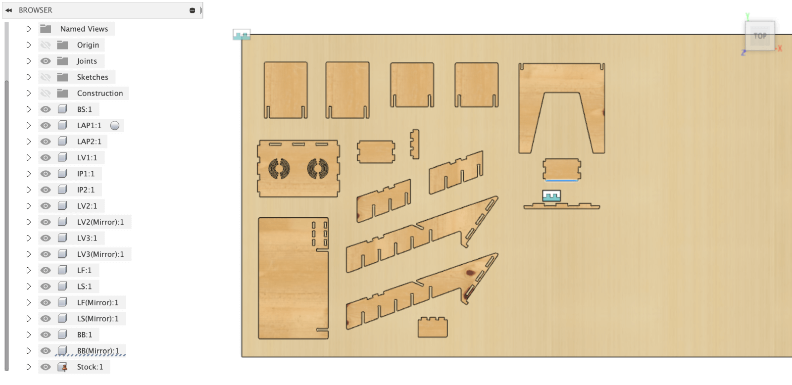
- Convert all available bodies into components
- Create a 2,400 x 1,250 x 9mm Stock component and Ground it
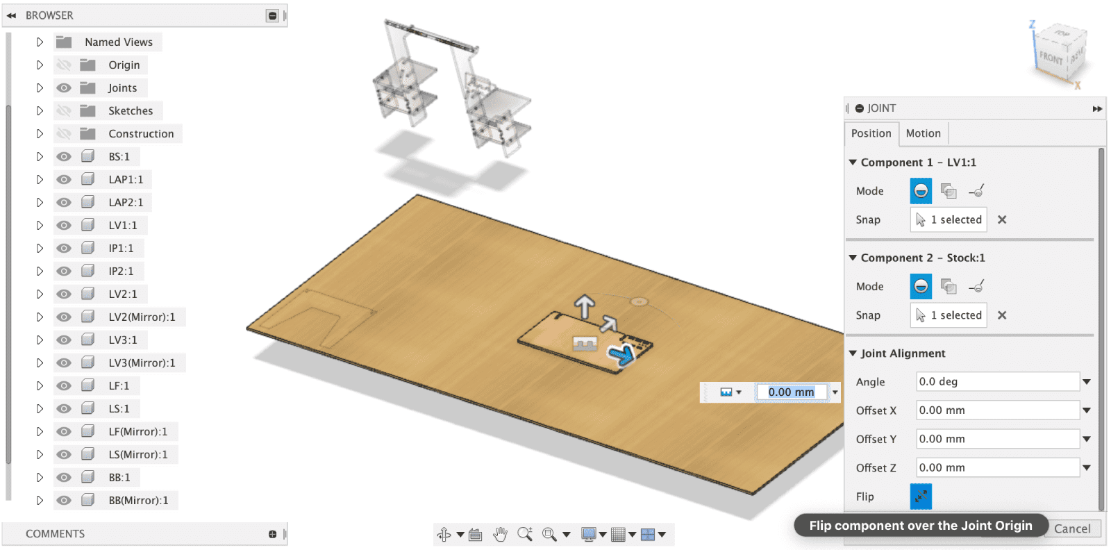
- Navigate to Assemble > Joints, select faces (which will be placed onto the stock) of all the bodies and create Planar joints
- Flip the pieces and Move them around to nest them within the stock
Below is the how-I-did-that video:
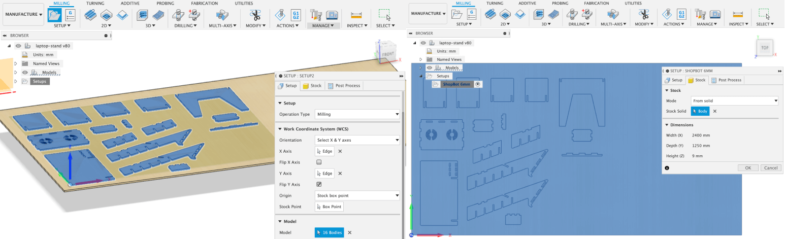
The next step was to create a ShopBot 6mm setup for generating toolpaths. Some steps to follow:
- Create a Setup > New Setup
- In the Setup tab, change Orientation to Select X & Y axes, select the longer side as X axis, the shorter side as Y axis, and select the left-bottom-upper point of the stock as the Stock Point
- For Model section in Setup tab, select all the parts to be cut
- For the Stock tab, select From solid mode and the stock component
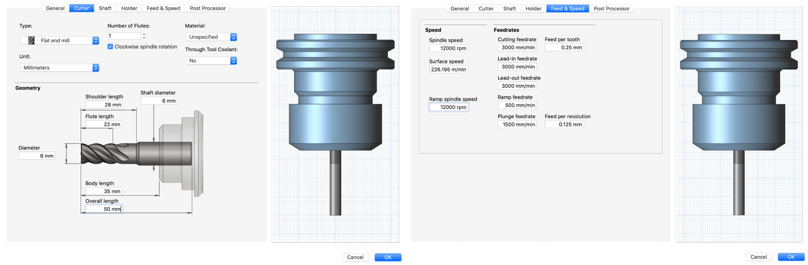
I used the same parameters as what Krisjanis did for creating a New Mill Tool in Manage > Tool library, and the final cutting feed rate I put in the Feed & Speed tab was 1 flute x 0.25mm x 12,000rpm = 3,000mm/min. A lower ramp and plunge feed rates of 500mm/min and 1,500mm/min were used.
I modified some other parameters in other tabs:
- In the Cutter tab, choose a Flat end mill with 1 flute, check the Clockwise spindle rotation option, and set Unit to Millimeters
- In the Geometry tab, set a 6mm tool diameter as we will mostly work with a 6mm tool, and some other parameters as the pictures below
- In the Post Processor tab, check the Manual tool change checkbox
To generate CAM toolpaths for my design, I had to perform 4 operations:
- Mark the position of the screws that we will use to fix the stock to the bed of the machine with a Drilling strategy
- Cut the invisible joints with a 2D Pocketing strategy
- Cut the inner parts of the pieces with an internal 2D Contouring strategy
- Cut the pieces out of the stock with an external 2D Contouring strategy
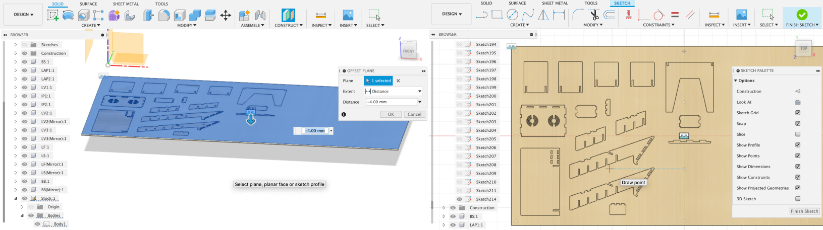
The first operation was drilling marks of the screw locations. First I had to go back to the Design environment, created a -4mm offset plan from the top surface of the stock component, and sketched points where I want to drill the marks. Then I switched to the Manufacture environment and created a New Operation > Drilling > Drill operation. In the Geometry tab, I selected all the points I recently created.
Here you go the yellow toolpath!
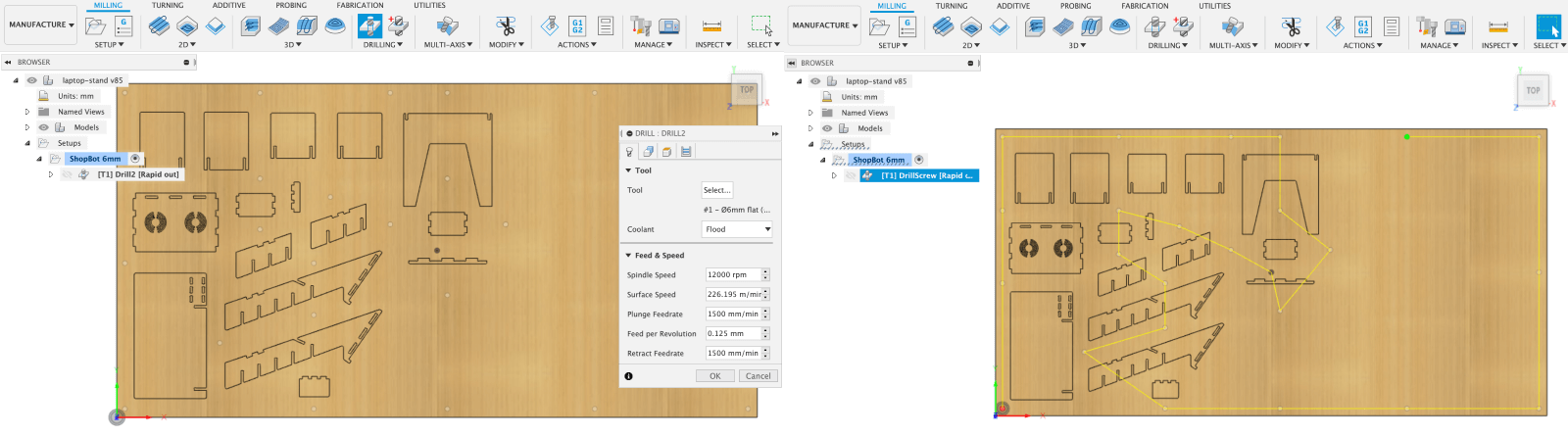
The next strategy was 2D Pocketing. Pocketing is for creating pockets or pits into the material and we can create invisible joints by using this strategy. I created a New Operation > 2D > 2D Pocket operation, and selected all the holes that I'd like to leave some materials unmilled in the Geometry tab. An important thing is the pockets need to be started inside, and we can check that by clicking the red arrows to see whether the blue areas are inside or outside the holes. In the Passes tab, I chose the Right (conventional milling) Sideways Compensation. I also put 5mm to all these sections: Maximum Stepover, Maximum Roughing Stepdown, and Finishing Stepdown.
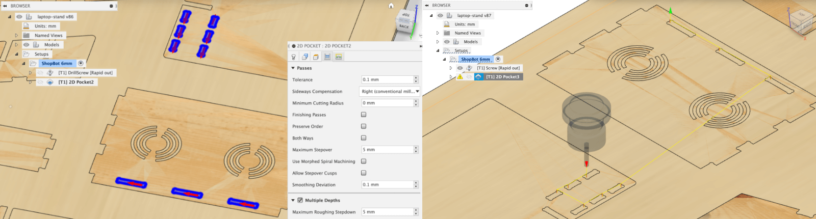
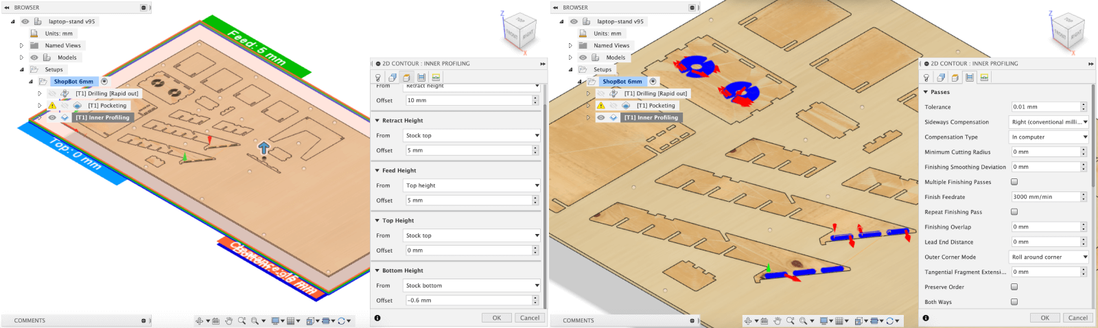
The New Operation > 2D > 2D Contour strategy in Fusion 360 is used to cut the pieces out by following their vector outlines, which works similarly to Profiling in RhinoCAM. In the Heights tab, I modified the Bottom Height as a -0.6mm offset from Stock bottom to make sure the material will be cut through completely. As a good practice, the internal contouring cuts need to be performed before the external ones:
However, I couldn't generate toolpaths for the circular air vents of the laptop holder for some reason which I haven't figured out. Hence, I decided to remove them from my design. Bad news: I had to go through the CAM process once again because the design was outdated!
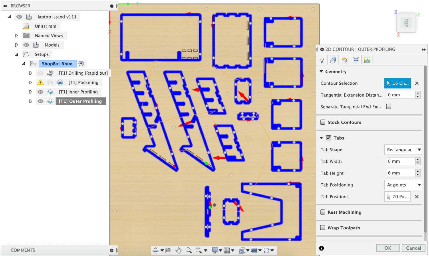
It is important to create Tabs in the Geometry tab for the external 2D contouring cut. Tabs keep the pieces to be removed in place while cutting material. If there are no tabs, the pieces can get loose or jump off, which can be very dangerous. I manually placed 4 tabs per piece, and the settings used are as below image (hope I didn't overdo it):
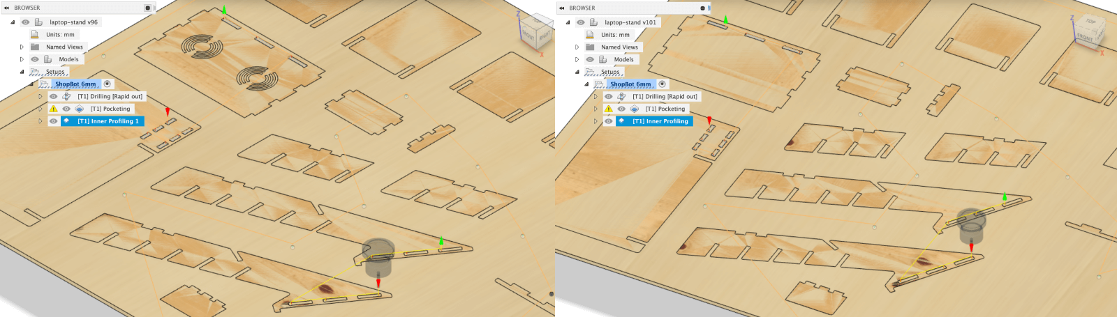
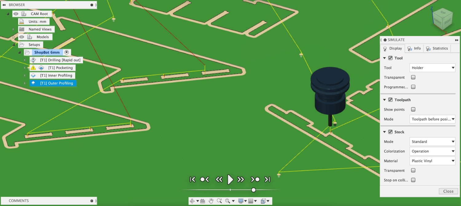
Before finalizing toolpaths, I navigated to Action > Simulate in order to check whether the plywood material will be removed as I wish. I was a bit worried about whether I should "drill" the dogbones separately, but after reviewing the simulation, everything seemed fine.
All toolpaths displayed:
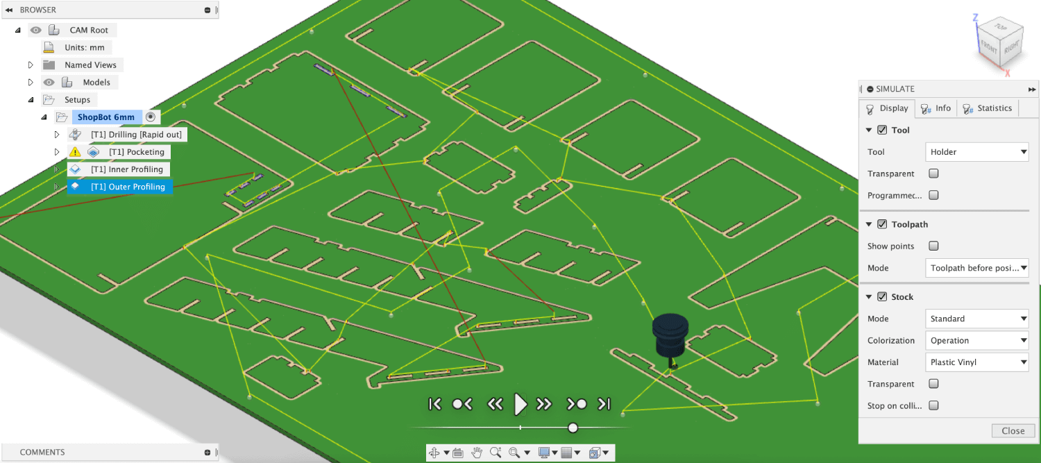
Below is the a video for the whole simulation:
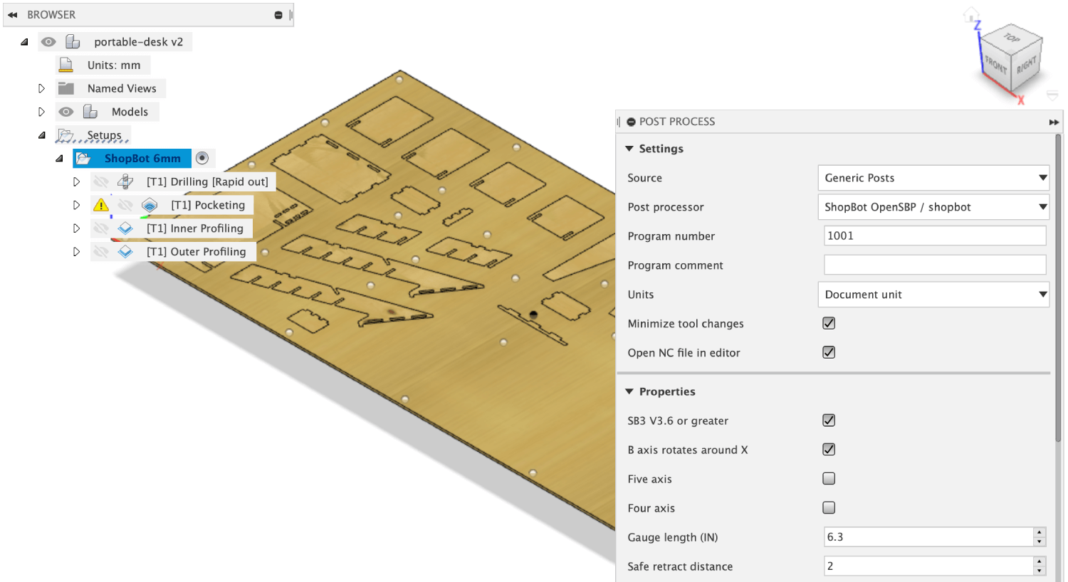
Now it's time to export the G-CODE! What to do is to navigate to Action > Post Process and look for a ShopBot post processor. I made a mistake by selecting the ShopBot ISO processor which generated a failed .nc file with the below error:
    ...
    Error: Failed to invoke function 'onSection'.
    ^^^^^^^^^^^^^^^^^^^^^^^^^^^^^^^^^^^^^^^^^^^^^
    Error: Failed to invoke 'onSection' in the post configuration.
    Error: Failed to execute configuration.
    Stop time: Thu May 21 19:45:36 2020
    Post processing failed
Finally I could export G-CODE by selecting the other ShopBot OpenSBP processor and generated an .sbp file. Ready to fabricate!
Generating toolpaths with RhinoCAM
After getting back to the lab, I realized (in tears) that we have to use RhinoCAM installed on the computers at Fab Lab in order to generate CAM files that are compatible with the available RaptorX-SL machine at the lab (there is no ShopBot machine as in 2018!). I had to export the design to .dxf and imported the file in Rhino 6. Then I navigated to RhinoCAM 2018 > Mill to see the RhinoCAM toolbar. Essential steps:
- Create a 2,400 x 1,250 x 9mm rectangle (the longer side is at the X axis), navigate to Stock > Box Stock, and select the stock object
- Select the right X0,Y0,Z0 (left-bottom-upper point of the stock)
- Create an inner offset of 20mm and create multiple screw marks along the offset line
- Create a 1-flute new down-cut Flat-end Mill 6mm with settings similar to what we did above with the group assignment (1 flute x 0.3mm x 18,000rpm = 5,400mm/min)
The drilling operation in RhinoCAM is called 2 Axis > Engraving and the contouring operation is called 2 Axis > Profiling. It is a good practice to create layers for engraving, pocketing, inner profiling, and outer profiling.
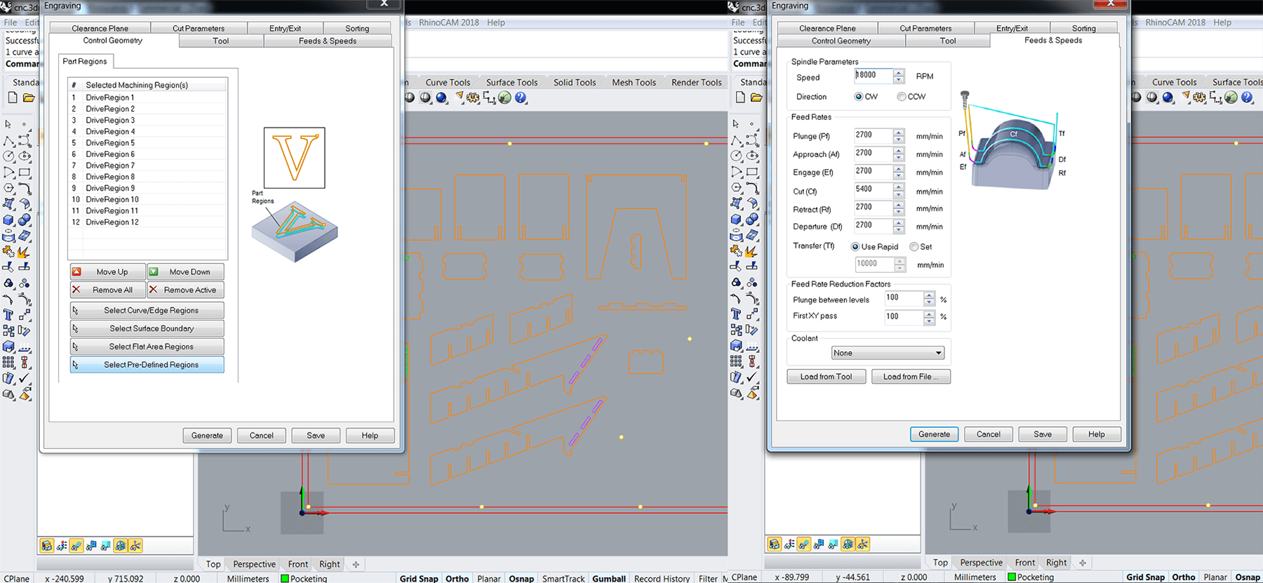
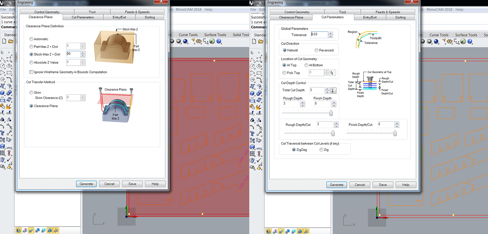
Clearance is similar to zjog setting while using the small milling machine. It is the distance above the material when the end mill rapidly changes its location. For the Engraving operation, I filled the Clearance Plane > Stock Max Z + Distance with 30mm and the Rough Depth Cut with 3mm. Also, I chose Minimum Distance Sorting in the Sorting tab (this will be the same for all the strategies).
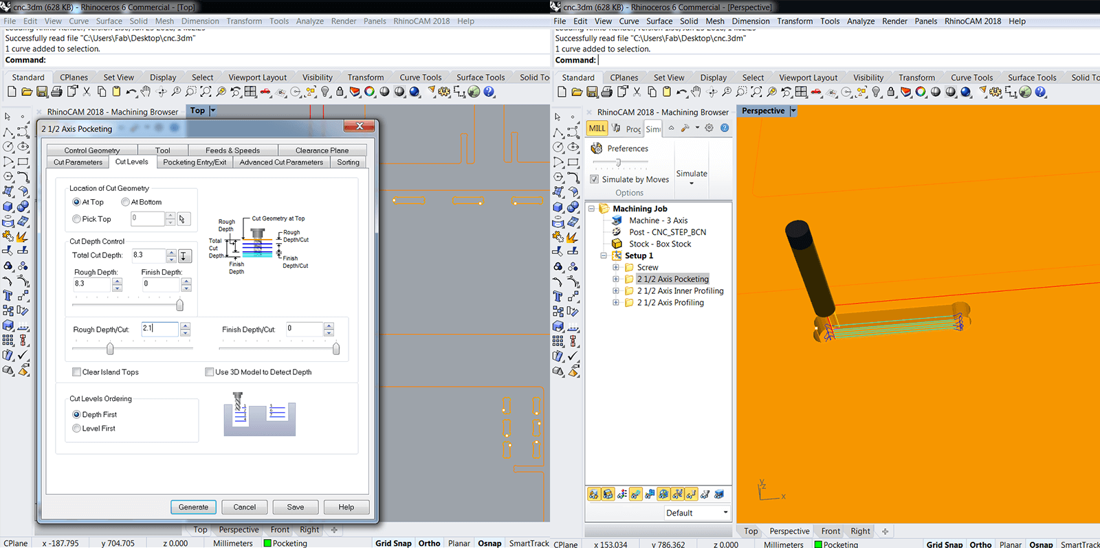
For the Pocketing strategy, I filled the Clearance Plane > Stock Max Z + Distance with 10mm. Next, I navigated to the Cut Parameters tab. Here I defined how the tool should move along the line and in what direction it should spin. In Global Parameters, I specified Stock to be 0 and left everything else as default. Remember to choose Climb (Down Cut) direction and Inside start point.
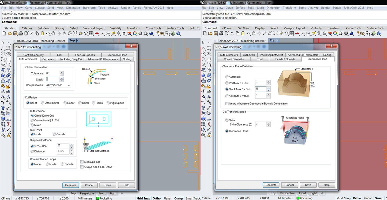
I specified how much material I want to keep in the Cut Levels tab. I wanted to leave 1mm of material to create invisible joints, so the Total Cut Depth in this case was 8.3mm. We were told that Rough Depth Cut should be less or equal to the diameter of the tool (which means each cut level should be 3mm maximum), so I put 2.1mm here, then there will be 4 cut levels. Clicking Depth First would help to fasten the process since it would reduce the traveling time of the tool. Also, I could right-click and preview the simulation of the created strategies.
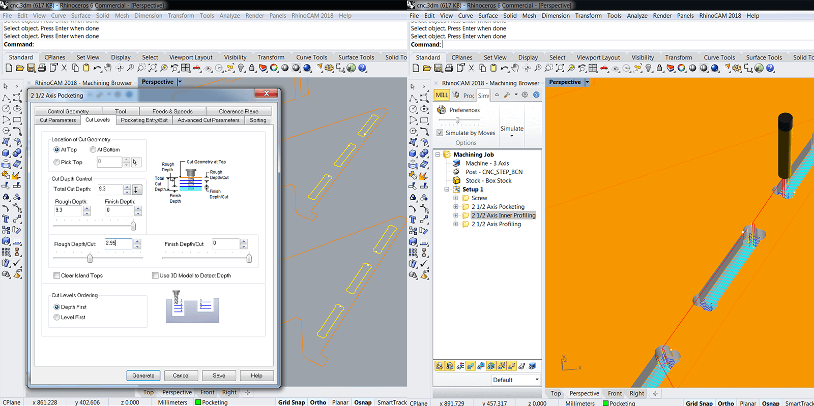
My Inner Profiling was basically the Pocketing operation with no material left. The Total Cut Depth in this case was 10mm as I added 0.7mm more in order to make sure that the tool cuts through.
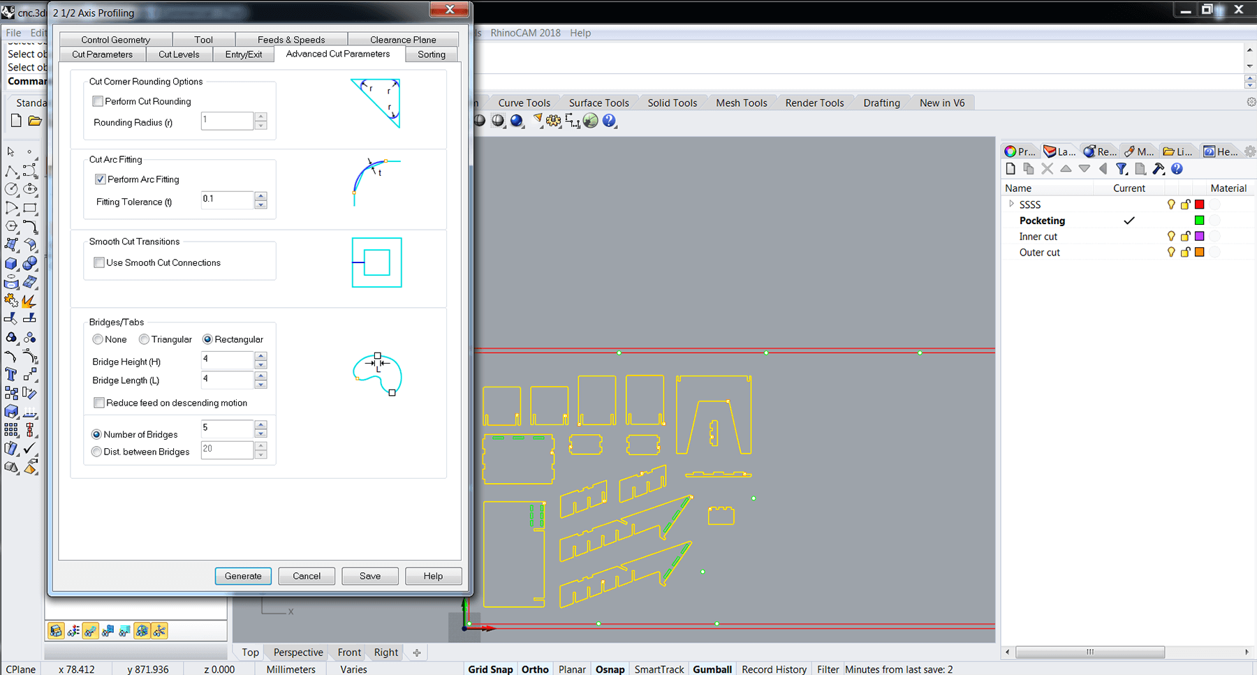
Profiling cuts follow a line from the inside or outside. In my case, I chose Outside. As in Fusion 360, I had to create tabs for the Outer Profiling operation. Tabs keep the pieces to be removed in place while cutting wood, and if there are no tabs, the piece can get loose, jump off and hurt people. I increased the frequency of tabs to 5 tabs per piece.
Machining with RaptorX-SL
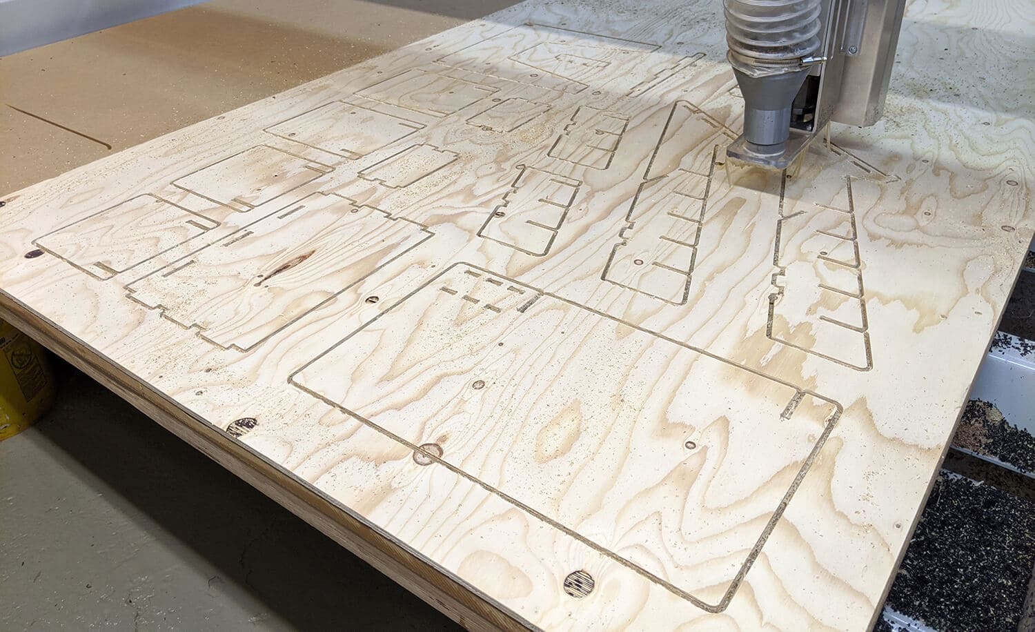
I did my individual assignment right after the group test, so I had all the setup ready (finding X0,Y0,Z0 and putting the tool). The next step was to launch the .nc file with the marks for the screws, to drill the stock down, and to launch the rest of the job.
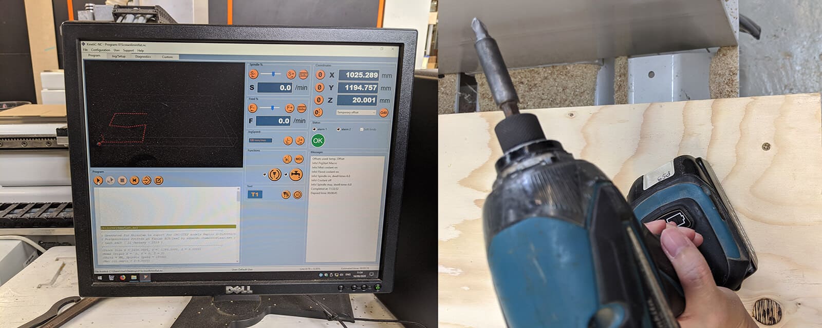
Below is a video recording the process:
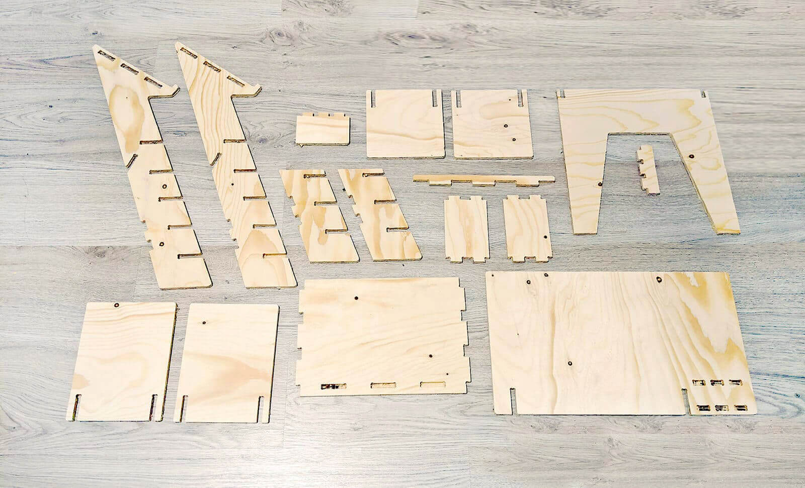
Milling job is done!
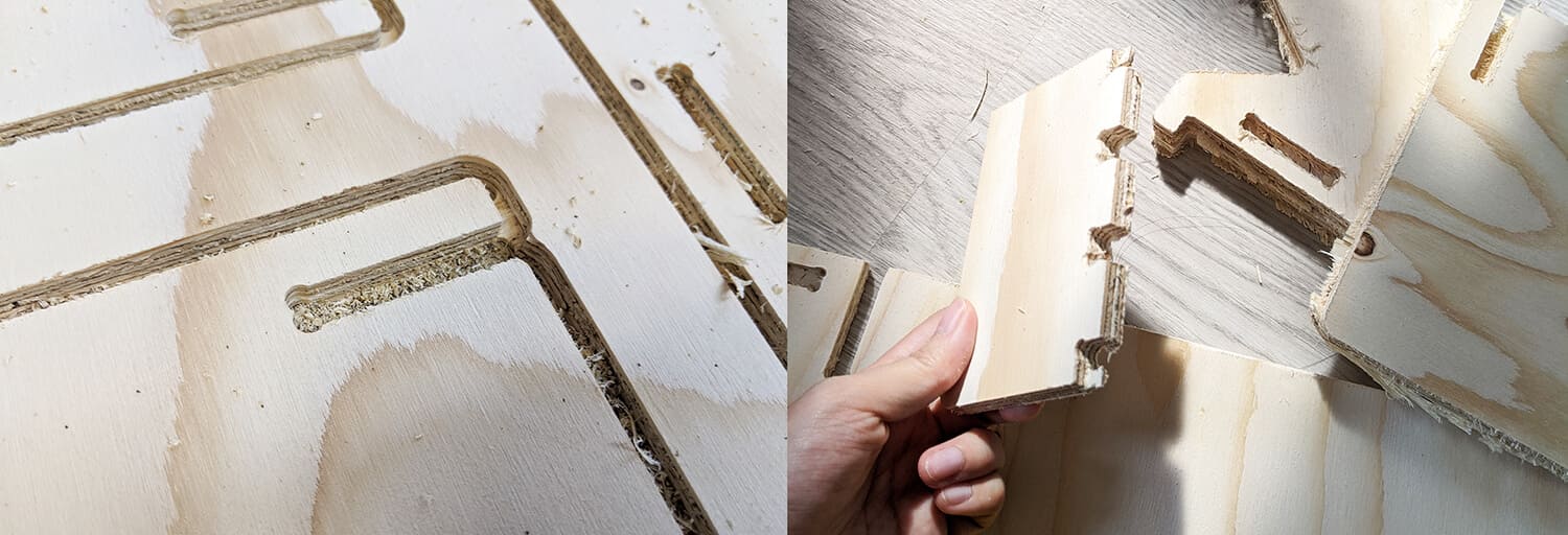
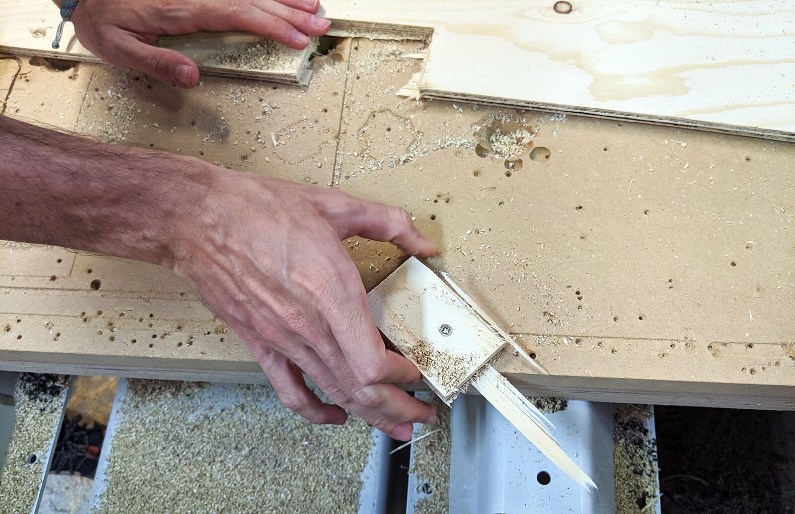
I used a hammer and a chisel to cut the tabs and remove the pieces from the stock. Sad news: they don't fit together. Then I realized I made a HUGE mistake: I didn't measure the material before finalizing the design! The actual thickness of the material is 9.3mm, not 9mm! (the above screenshots were taken during the 2nd time generating the CAM files). Also, I didn't increase the Profiling's Total Cut Depth to be a bigger number than 9mm, and that's why the quality of the job was not good at all.
So, I had to re-design my .dxf file, re-did the CAM files, and performed the jobs again. That was quite stressful! This time, my classmates Arman and Antoine helped me a lot in handling the screws. In the end, 1 screw was fucked up, and we were unable to take it out. Josep had to quickly create a file in RhinoCAM (which we named FuckedScrew.nc) and cut a rectangular piece, and then manually rotated it to remove the fucked-up screw. Annoyingly problematic screw!
Final result
I brought the final result home for assembling. Although I was quite satisfied with the quality of the 2nd cut, however, I still had to sand the pieces a lot by hand (especially areas with dogbones) to make them fit properly. There were some parts that hadn't been cut through, but they're not the important parts or joints.
And here you go the final product after assembly. We can notice that some joints didn't actually fit 100% all the way, but I left them like that since I was too tired to keep sanding, and the portable desk already stood super strong and stable. Fancy, huh? Totally!
Conclusion
This was one of the last assignments regarding CAM techniques and also our last opportunity to work with the biggest machine in the lab before saying goodbye to the Fab Academy. It may sound ridiculous to some extent, but I was quite obsessed with the story that Neil told us about a girl who died using a CNC machine. I was so worried that I would be the second one to have a tragic accident, but in the end, I felt very confident and comfortable working with the machine, and the whole process went smoothly. I'm so proud of myself!