Machine_Building
Group Assignment
- Design a machine that includes mechanism + actuation + automation + application
- Build the mechanical parts and operate it manually
- Actuate and automate your machine
- Document the group project
Overview
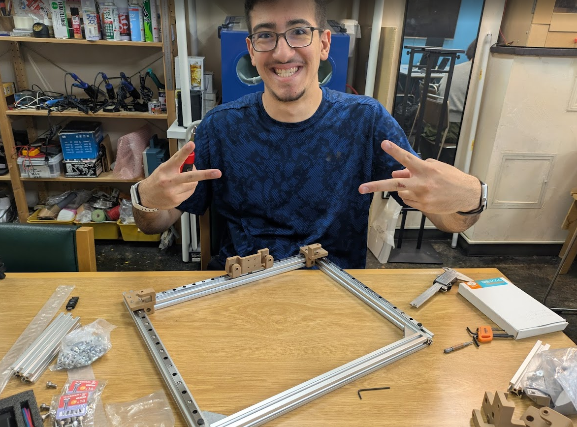
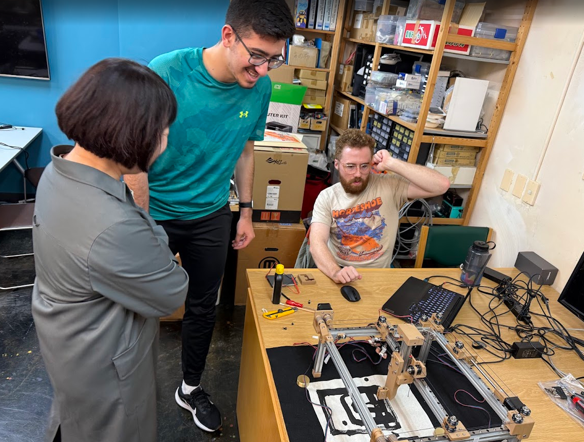
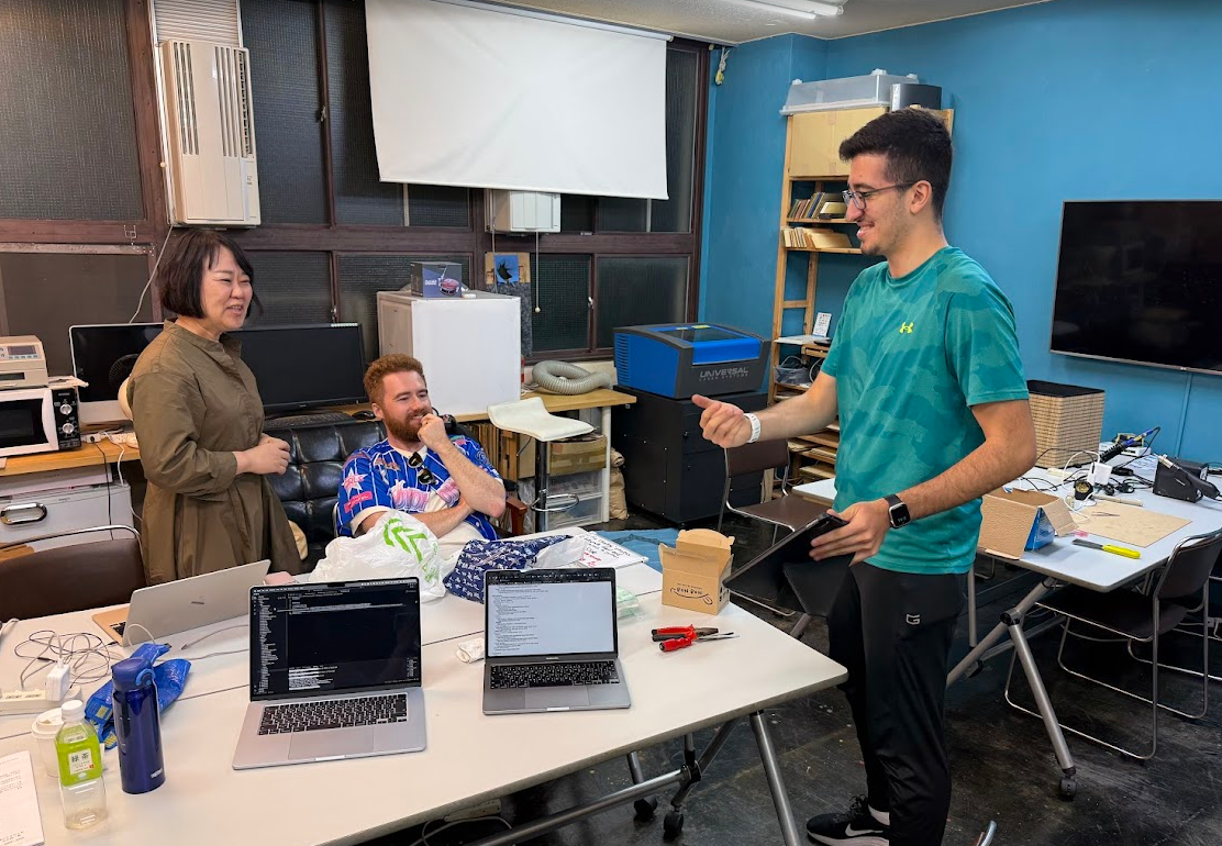
Our first group assignment together as a team! Welcome Kieran and Youssef to Yokohama!
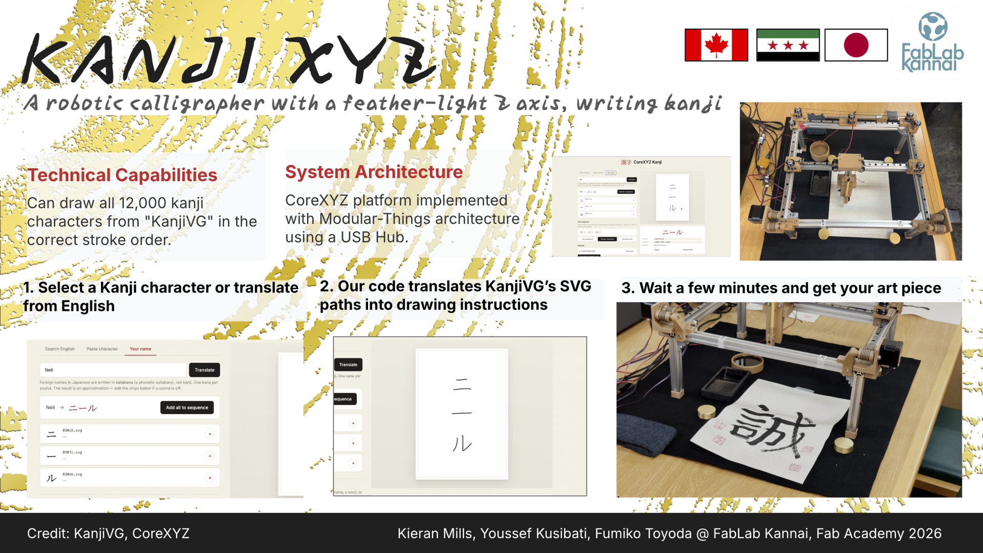
We wasted no time getting started after our introductions! Yuichi had a prototype built of the brand new CoreXYZ system that he learned about during his time at the 2026 Instructors Bootcamp with Quentin Bolsee and which was briefly touched on during this week’s lecture. Thanks to Yuichi’s prototype, we were able to get a good look at it and study how it functioned before designing our own system.
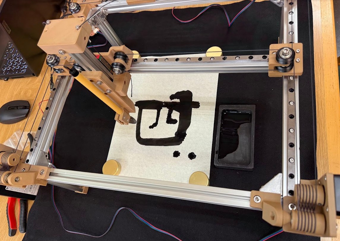
Our first day was all about defining the scope of our machine and our action items for the coming days to make sure we could finish by our goal of Friday. After some chatting, we decided that we would want our CoreXYZ-based machine to be able to draw Kanji (Japanese characters) with a paintbrush! We sat down to scope out the materials we would need, what work would need to be done individually and together, and what we needed to prioritize.
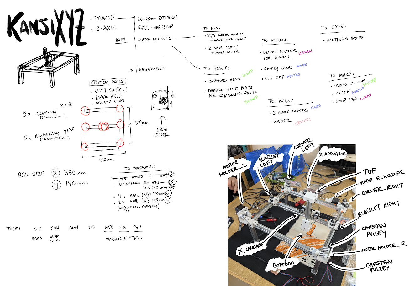
The first thing we did was take inventory with reference to this spreadsheet and order the missing parts. We also made the decision here as to what size our “canvas” would operate. Quentin’s documentation shows a much smaller machine to show off his proof of concept, so we decided to order aluminum extrusion that would better fit our needs, which required 5 lengths of 390mm for the X/Y plane and 5 lengths of 140mm extrusion for the Z axis and the legs. We found some linear rails on Amazon that could be delivered within the weekend, and opted to purchase some wood filament PLA to give our device a much more fitting look for the end purpose. Youssef and Yuichi carefully checked all of the bolt lengths in use for the prototype to ensure we had the right hardware to get started.
Once our purchases were out of the way, it was time to start delegating tasks and start working!
Bill of Materials
Here are the main parts that make up the machine. We took this list from here and ordered most of the metal and motion hardware from Misumi and Amazon Japan.
You can also download the full bill of materials (machine and board) as a spreadsheet.
| Item | Spec | Qty | Source |
|---|---|---|---|
| Aluminium extrusion | 2020, 390mm | 5 | Misumi |
| Aluminium extrusion | 2020, 140mm | 5 | Misumi |
| Bracket | 5 series | 4+8 | Misumi |
| T-nut | M3 | as needed | Misumi |
| T-nut | M5 | as needed | Misumi |
| Miniature guide rail | MGN9 350mm with MGN9H block | 4 | Amazon |
| Miniature guide rail | MGN9 100mm with MGN9H block | 2 | Amazon |
| Lead screw | Tr8x8 (Ø8, pitch 2, 4 starts) | 1 | Amazon |
| POM anti-backlash spring nut | For Tr8x8 | 1 | Amazon |
| Kevlar thread | Ø1.6mm | 1 | Amazon |
| Hex socket head bolts | M3 | as needed | Misumi |
| Hex socket head bolts | M3, M5 | as needed | Monotaro |
| V-wheel | POM | as needed | AliExpress |
| Powered USB hub | Individual switches | 1 | Amazon |
| USB cable | USB-C to USB-A 3.0 | 3 | Amazon |
We left the bolt lengths and counts open. They were too fiddly to pin down up front, so we sized them against Yuichi’s prototype as we assembled, and the exact mix depends on how your printed parts stack up.
Individual Documentation
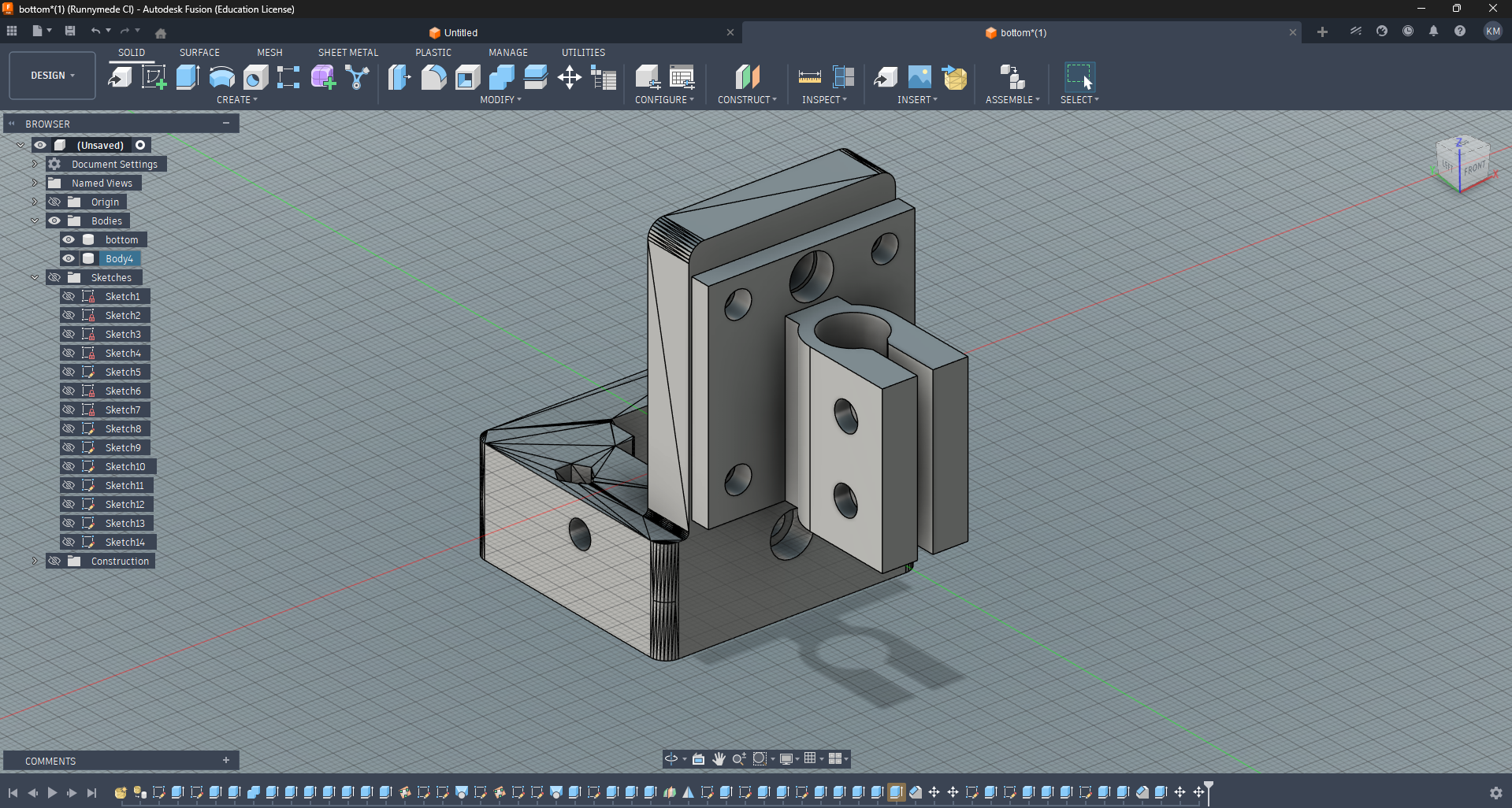
Modifications to 3D Models
Youssef
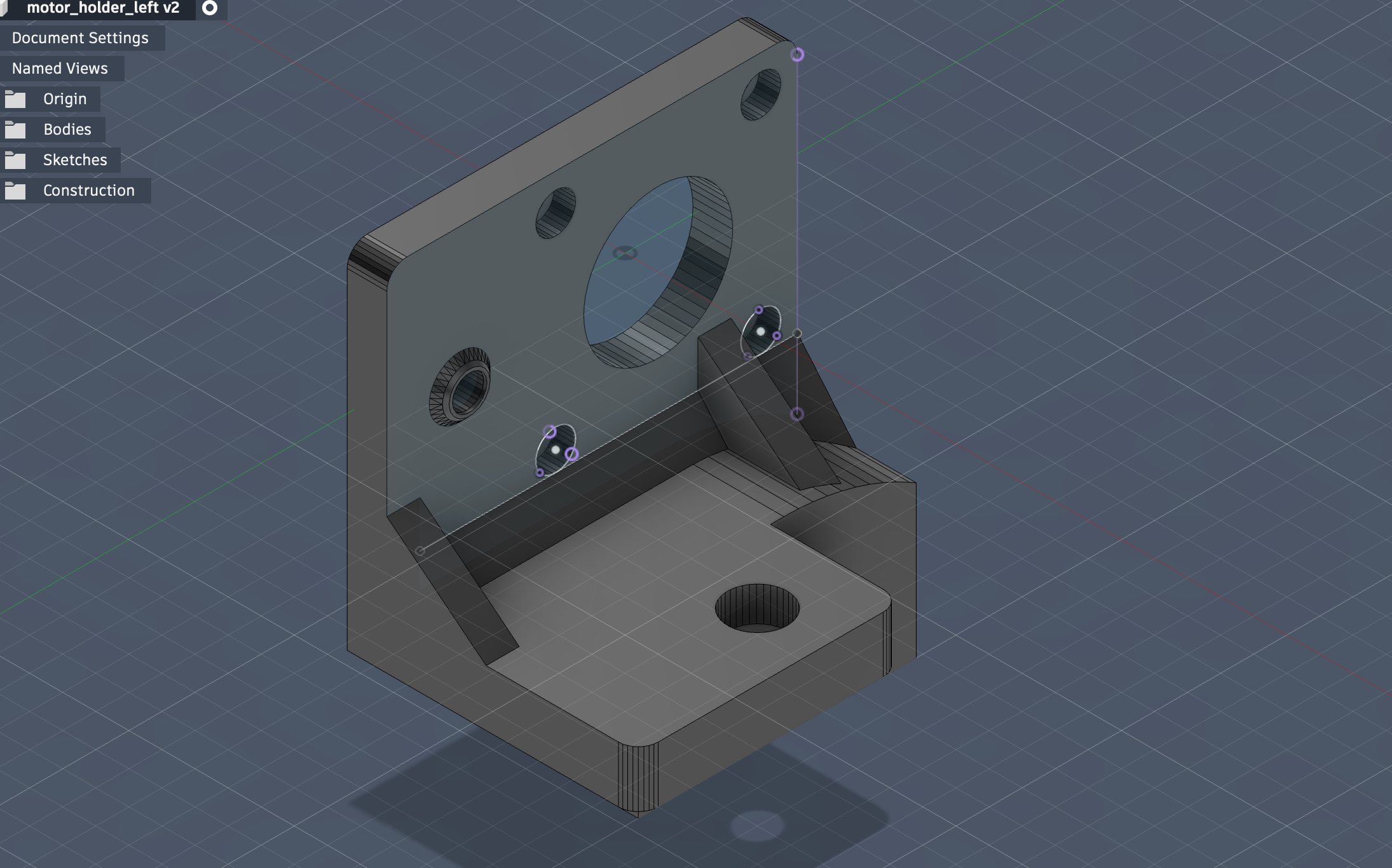
We required a few modifications to the stock files provided to us by Quentin through Yuichi. We needed to make the caps for the Z-axis gantry wider to properly line up with the pulley system.
We also decided that the motor mounts where the capstans interface needed a bit more support; the sizes of some of the nut slots needed to change; and we needed to change the thickness of different elemntsto work better with all the screws.
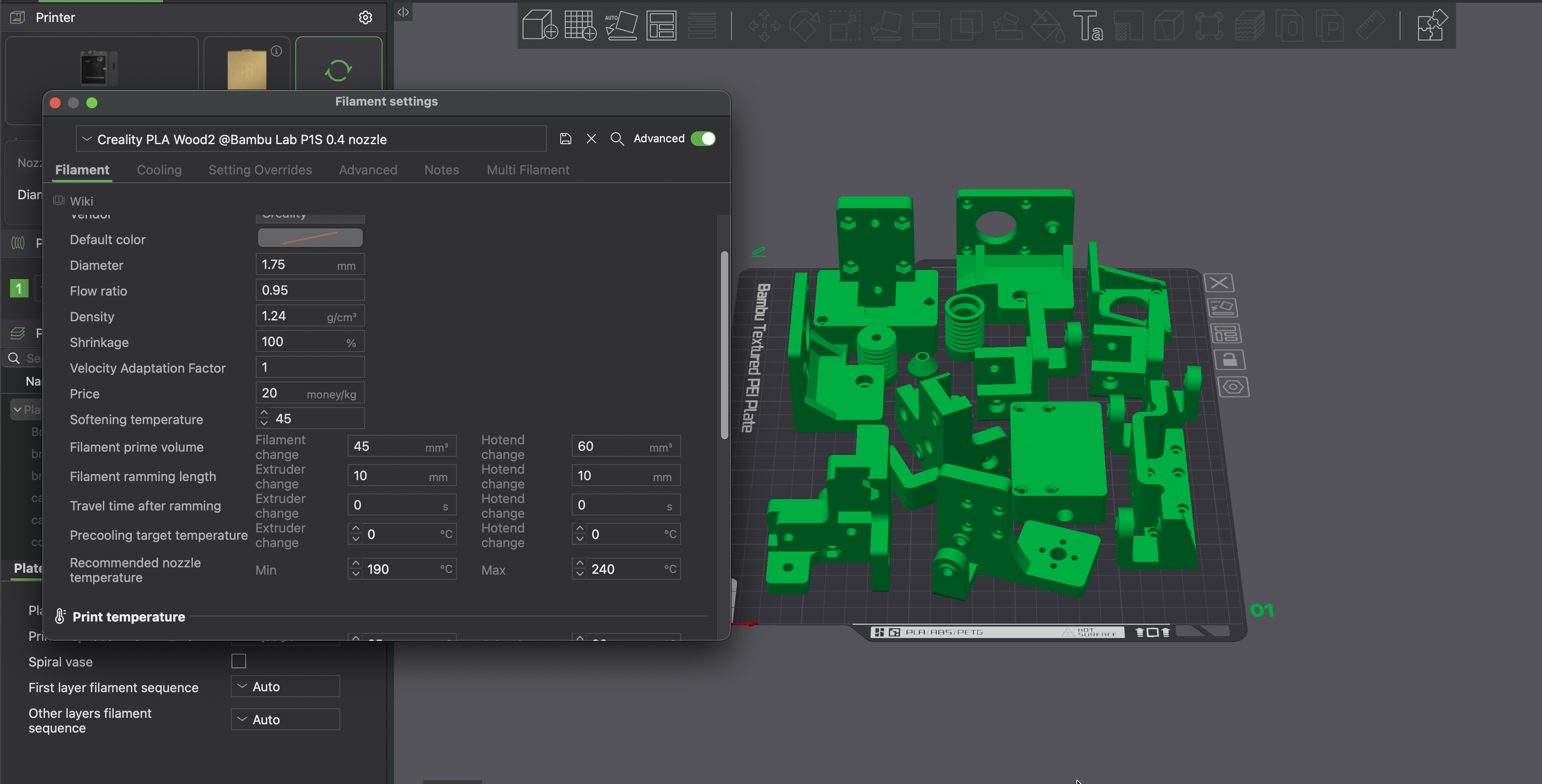
Youssef took the lead on redesigning these and getting them printed. We also had a hard time printing the new wood filament PLA on our lab’s P1S printer, so Youssef thankfully created a custom filament profile for us to import into our slicers that handled the extrusion better.
Additional 3D Models
Brush Holder
Kieran
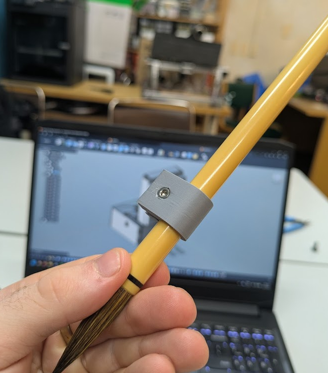
Kieran designed a clamp for the brush purchased at DAISO earlier that day. It works by allowing the PLA to flex a little to insert the cylinder, and then it can pinch the brush in place with a few nuts and bolts.
Decorative Feet
Fumiko
Fumiko designed decorative feet for the aluminum extrusion legs to give our machine a professional and quality look.
Limit Switches
Fumiko
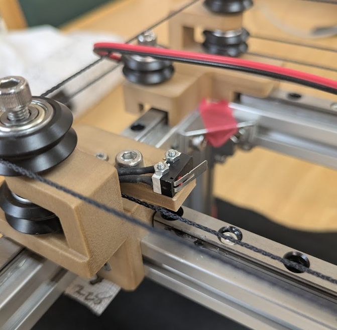
Fumiko designed and printed mounts for the microswitches that would serve as our limit switches. They could be easily bolted to existing holes on the other 3D printed parts, aside from the Z axis, where we needed to drill a small hole to accommodate the bolt.
Smaller Brush Adapter
Youssef
After realizing our first brush choice was a bit thick for more complex Kanji, we decided to use a thinner brush. Not wanting to reprint the whole brush holder with a new diameter, Youssef printed an adapter that could fill the space between the two brush thicknesses.
Water Dish
Fumiko
Fumiko designed and printed a matching water dish to allow our machine to clean the brush in some water so we didn’t have to fully unmount the brush when we went on our lunch breaks.
3D Print Files
These are the printed parts that make up the frame and motion system. They started from Quentin’s CoreXYZ files, edited with the tweaks described above.
Download all the 3D print files here: kanjixyz_3d_print_parts.zip
Download the parts individually
- bottom.3mf
- top.3mf
- corner_left.3mf
- corner_left_v2.3mf
- corner_right.3mf
- bracket_left.3mf
- bracket_right.3mf
- motor_holder_left.3mf
- motor_holder_right.3mf
- motor_z_holder.3mf
- capstan_motor.3mf
- capstan_pulley.3mf
- cone.3mf
- pulley_holder_left.3mf
- pulley_holder_right.3mf
- pulley_holder_right_v2.3mf
- x_carriage_MGN9H.3mf
- z_actuator_MGN9H.3mf
- cable_covers.3mf
The _v2 files are the revised versions of those parts.
Microcontrollers and PCBs
Fumiko
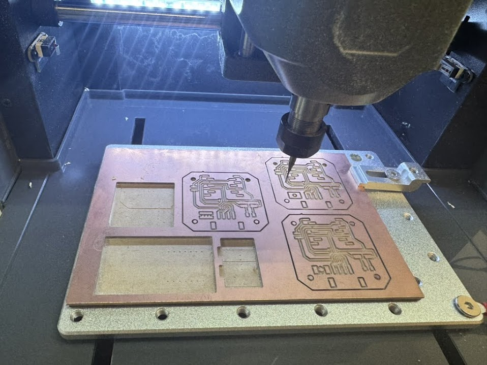
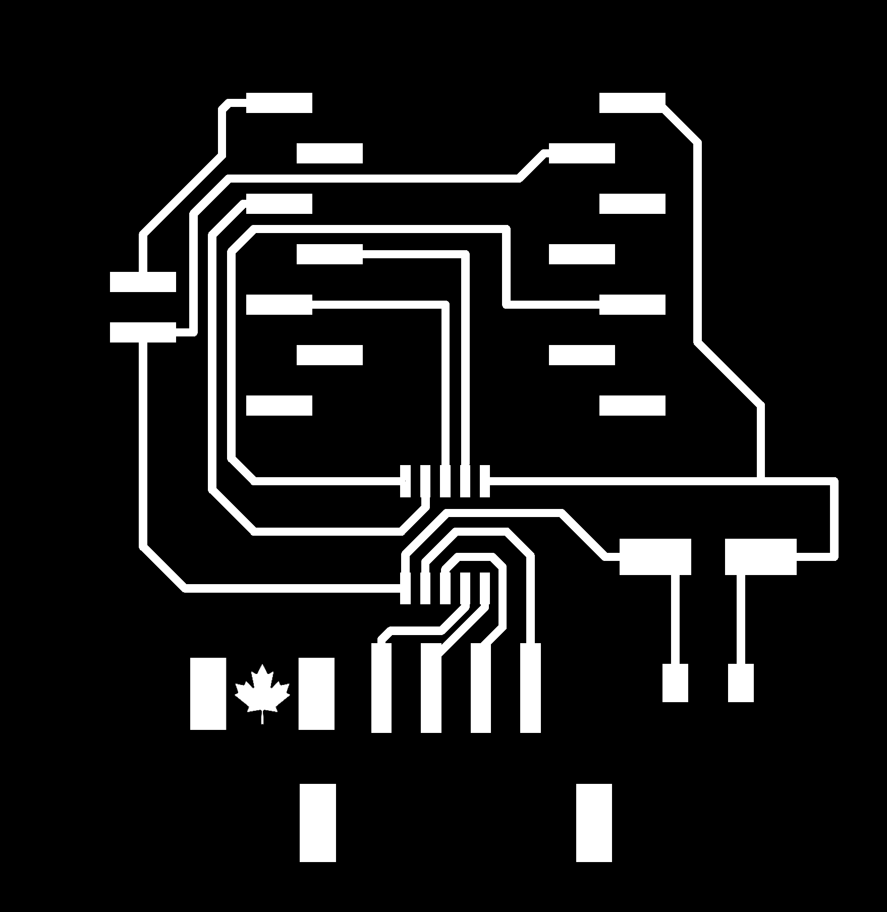
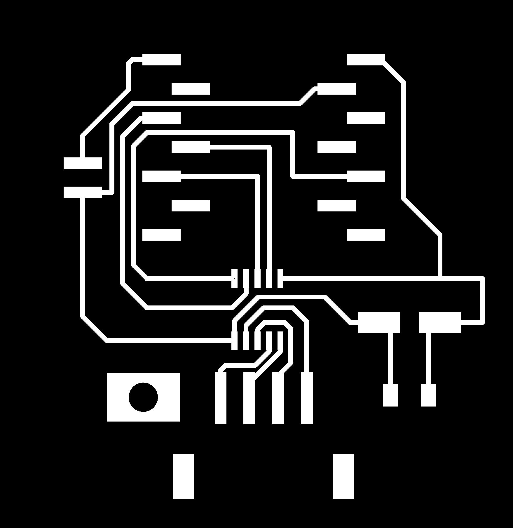
Fumiko designed and milled three new motorcontroller PCBs to control each of the stepper motors. She also included the flags of each of our origin countries (Canada, Syria, Japan) on the boards!
Here are the mill layouts for the three boards, one country flag each.
| Canada | Japan | Syria |
|---|---|---|
 |
 |
 |
Board Bill of Materials
All three boards carry the same parts. We took the design and the component list from here.
| Item | Qty |
|---|---|
| XIAO RP2040 | 1 |
| DRV8421A dual H-bridge stepper driver | 1 |
| 100µF capacitor | 1 |
| 0.1µF 1206 capacitor | 1 |
| S4B-XH-SM4-TB or 1x4 SMD pin header | 1 |
| 1x2 SMD pin header | 1 |
| 1x7 SMD vertical pin socket | 2 |
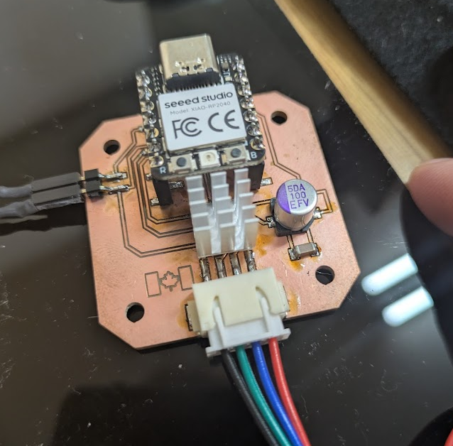
Soldering
Youssef, Fumiko, Kieran
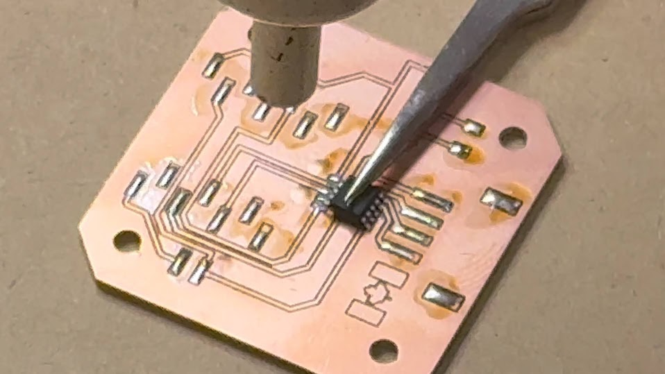
We utilized a mix of hand soldering and reflow soldering with the heat gun to solder each of the components (pin headers for XIAO RP2040, H-bridge SOIC, capacitor, molex pinheader and pin headers for the limit switches) to the board.
Assembly
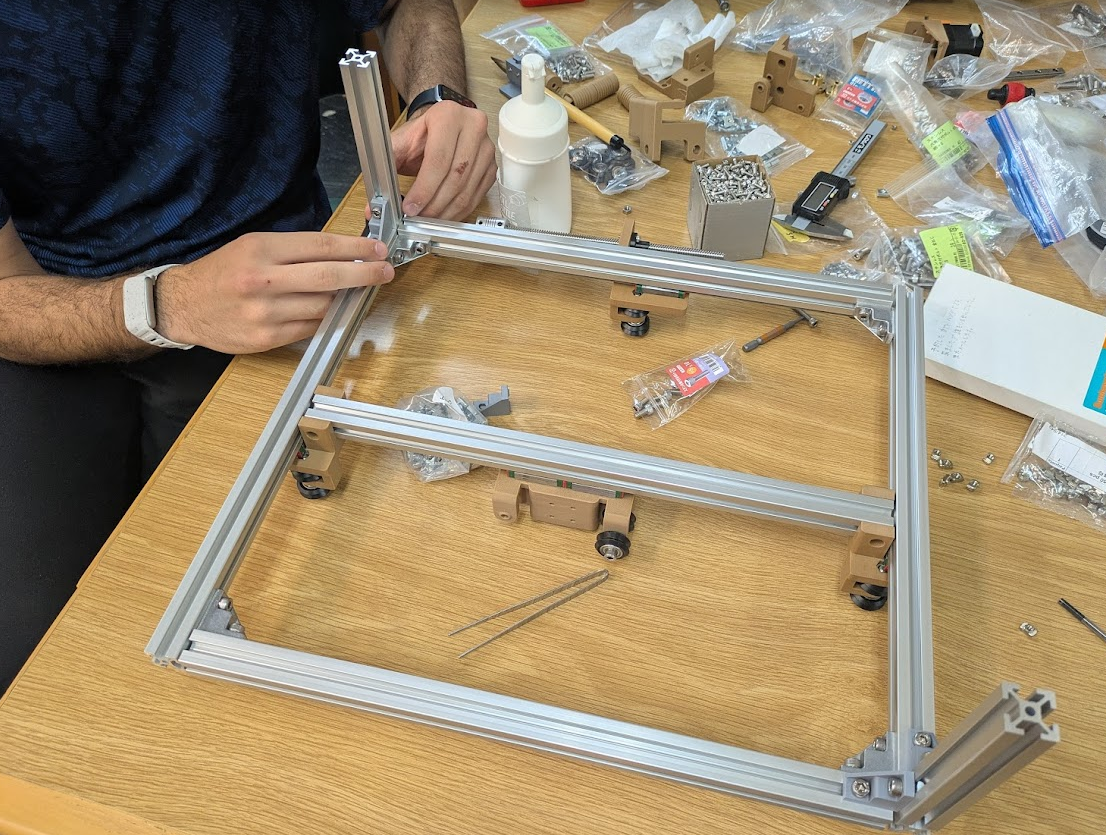
Youssef, Fumiko, Kieran
Using Yuichi’s assembled prototype and Quentin’s documentation page as reference, we assembled the machine! Some tips for anyone having trouble assembling this:
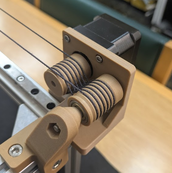
-
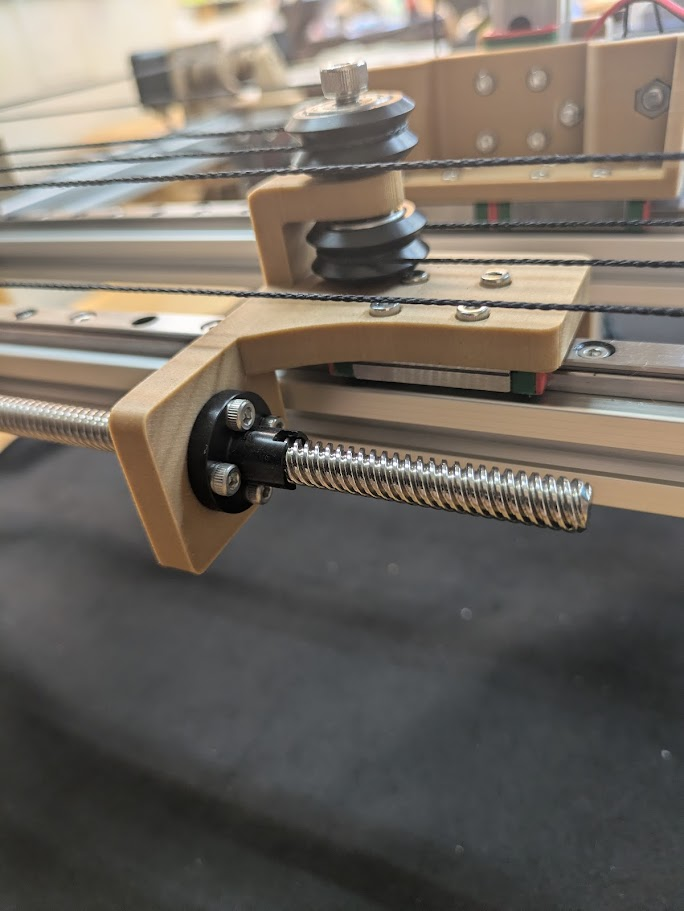
Ensure your capstans have the correct number of revolutions and that the threads leave at the same height they enter. In this image you can see the thread coming in at the top level and leave at the top level as well. Pay close attention to the capstan threading and the criss-cross of the kevlar needed.
-
Also note the direction of the cone-shaped part. It should be facing in toward the capstan. Don’t overtighten the bolt that runs through this axel!
- Tension the threads with the back lead screw cap fully removed. In this image, it is fully screwed in, remove all 4 screws so that the Z axis pulley/gantry system right next to it can move freely back and forth when your threads are being tensioned.
- Fumiko carefully measured out the kevlar thread for each motor.
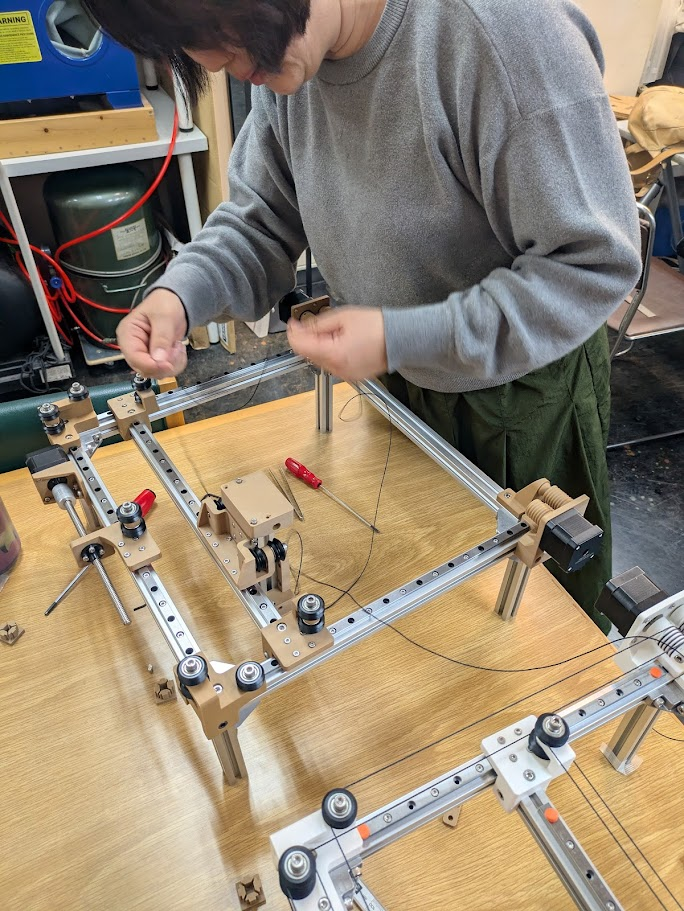
Apart from that, just make sure everything is nice and squared up! Don’t take shortcuts here because your resulting machine will not like any stray angles!
A demonstration of the effector moving with manual control (no electricity!).
Firmware
Each board runs the same firmware, an Arduino sketch called simple stepper that we flashed onto its XIAO RP2040. It comes from Quentin’s modular printable axis project and is the starting point the Kannai prep page points to.
The firmware listens on USB serial for a target position, decodes it with COBS, and drives the DRV8421A H-bridge to step the motor. The Python control code below (the goto_xyz() calls) is what sends those targets to each board.
The pin definitions match the boards we milled. The H-bridge inputs and the limit switch sit on these XIAO pins:
#define AIN1_PIN 29
#define AIN2_PIN 6
#define BIN1_PIN 4
#define BIN2_PIN 28
#define PIN_LIMIT 26
The XIAO runs at 200MHz. The full sketch (the COBS serial layer, the motion state machine, the stepper driver and its lookup table) lives in the prep page’s simple stepper folder.
KanjiVG
Kieran
Early in development, Kieran found a resource online called KanjiVG which contained files for the over 10,000 kanji characters we would want our machine to be able to draw. The repo contains data for all of the stroke information for each kanji, including the stroke order and the small nuanced paths that are required to draw each Kanji accurately.
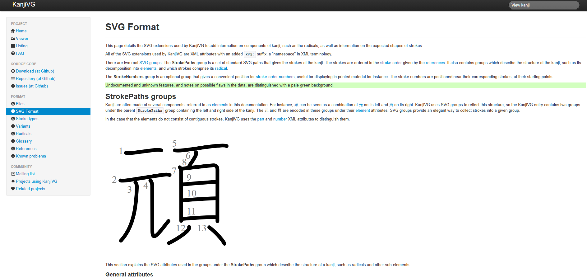
Within each of these SVGs contains vector paths that we could extract and convert into XY coordinates for our machine. Below is an excerpt from the SVG file (which is basically just an XML document with a list of vectors that make up the image or text in the file) for the Kanji “組” (class of students) where you can see each element of the kanji defined as a series of “d” paths.
<g id="kvg:07d44" kvg:element="組">
    <g id="kvg:07d44-g1" kvg:element="糸" kvg:position="left" kvg:radical="general">
        <path id="kvg:07d44-s1" kvg:type="㇜" d="M29.36,13.5c0.53,2,0.21,3.32-0.93,5.03C24.81,24,20.5,30.75,16.47,35.03c-0.64,0.68-0.72,2.22,0.5,2.7c3.54,1.39,7.51,2.92,10.58,5.26"/>
        <path id="kvg:07d44-s2" kvg:type="㇜" d="M41.28,23.94c0.59,2.06,0.34,3.18-1.2,5.12c-6.78,8.53-16.25,19.61-23.43,27.05c-1.74,1.8-0.65,3.01,1.57,2.47c5.67-1.39,15.12-4.02,21.23-5.49"/>
        <path id="kvg:07d44-s3" kvg:type="㇔" d="M37.75,46.5c2.38,2.12,6.15,8.71,6.75,12"/>
        <path id="kvg:07d44-s4" kvg:type="㇑" d="M29.85,59.01c0.9,1.24,1.16,3.24,1.16,4.7c0,13.05,0,20.59-0.22,27.55c-0.07,2.26-0.12,4.02-0.12,5"/>
        <path id="kvg:07d44-s5" kvg:type="㇒" d="M19.63,69.88c0.19,1.31,0.29,2.26-0.19,3.46c-1.54,3.79-4.88,10.28-6.69,13.17"/>
        <path id="kvg:07d44-s6" kvg:type="㇔" d="M39.5,67.5c2.75,3.61,4.86,11.98,5.5,15.25"/>
    </g>
    <g id="kvg:07d44-g2" kvg:element="且" kvg:position="right" kvg:phon="且">
        <g id="kvg:07d44-g3" kvg:element="月">
            <path id="kvg:07d44-s7" kvg:type="㇑a" d="M54.21,21.59c0.97,0.97,1.43,2.53,1.43,4.06c0,0.89,0.12,45.52,0.12,59.34c0,2.23,0,3.66-0.01,3.97"/>
            <path id="kvg:07d44-s8" kvg:type="㇕b" d="M56.8,23.76c6.84-0.85,22.52-3.05,23.81-3.19c3.03-0.31,4.81,1.67,4.81,3.73c0,2.82-0.2,36.53-0.27,57.44c0,1.47-0.01,2.87-0.02,4.19"/>
            <path id="kvg:07d44-s9" kvg:type="㇐a" d="M56.88,45.15c7.76-1,20.45-2.19,27.27-2.5"/>
            <path id="kvg:07d44-s10" kvg:type="㇐a" d="M57.34,65.11c7.54-0.86,18.41-1.73,26.33-2.06"/>
        </g>
        <g id="kvg:07d44-g4" kvg:element="一">
            <path id="kvg:07d44-s11" kvg:type="㇐" d="M43.79,90.07c1.99,0.43,5.39,0.32,7.37,0.18c12.34-0.88,27.34-2.13,41.51-2.41c3.31-0.07,5.3,0.21,6.96,0.42"/>
        </g>
    </g>
</g>
</g>
Kieran wrote a script to help us extract these strings and convert them into XY coordinates which later went on to form the basis of the final python script for the machine. The script functions by opening up the desired .svg file and looking for the elements that begin with that “d” attribute with the “path” tag, and pushing them into a string, essentially clearing all the non-required parts of the .svg file.
import os

def extract_svg_paths(svg_filepath):
    tree = ET.parse(svg_filepath)
    root = tree.getroot()
    path_strings = []
    for elem in root.iter():
        if elem.tag.endswith('path'):
            d_attr = elem.attrib.get('d')
            if d_attr:
                path_strings.append(d_attr)
    return path_strings
The next part of the script takes the outputted string from the previous function and turns it into a series of XY coordinates. This is done by utilizing a great library for this function called svg.path which has a function called parse_path() that converts the text into geometric segments with ease. We had to make a call on how many “points” each path would be made out of, because these SVGs were defined by a lot of bezier curves that would be useless in an XY coordinate system, so we chose to average each stroke to 15 points and then have the script connect the dots between each of the segments in a curve. The result is a bit messy and overkill for shorter strokes, and it produces a bit of a slower toolpath for the effector, but it works!
import xml.etree.ElementTree as ET
from svg.path import parse_path

def discretize_path(d_string, num_points=15):
    #use the svg.path library to translate the <d> strings into coordinates
    parsed_path = parse_path(d_string)
    points = []
    draw_segments = [seg for seg in parsed_path if type(seg).__name__ not in ['Move', 'Close']]

    if not draw_segments:
        return points

    total_length = sum(seg.length() for seg in draw_segments)

    for i in range(num_points):
        t = i / float(num_points - 1)
        if total_length < 1e-5:
            pt = draw_segments[0].point(0)
            points.append((pt.real, pt.imag))
            continue

        target_len = t * total_length
        current_len = 0.0

        for seg in draw_segments:
            seg_len = seg.length()
            if current_len + seg_len >= target_len - 1e-6:
                seg_t = (target_len - current_len) / seg_len if seg_len > 0 else 0
                pt = seg.point(seg_t)
                points.append((pt.real, pt.imag))
                break
            current_len += seg_len
    return points
Lastly we want allow the machine to transit in between strokes, lifting the brush in the Z-axis before moving from the last point of the current stroke to the first point of the next stroke. This function just uses regular math (linear interpolation) to find the transit line between two strokes.
def generate_transit_line(x1, y1, x2, y2, steps=10):
    points = []
    for i in range(steps):
        t = i / float(steps - 1) if steps > 1 else 1.0
        x = x1 + (x2 - x1) * t
        y = y1 + (y2 - y1) * t
        points.append((x, y))
    return points
Then to get the pen to actually lift and lower to draw we call our movement function (more on that later) to navigate to those transit points but also to raise and lower the Z axis.
for pt in transit_points:
            mx, my = to_machine(pt[0], pt[1], scale)
            goto_xyz(m1, m2, m3, mx, my, z_up, vel, acc)

#lift
mx, my = to_machine(start_rx, start_ry, scale)
goto_xyz(m1, m2, m3, mx, my, z_down, vel, acc)

#draw
for pt in stroke_points[1:]:
    mx, my = to_machine(pt[0], pt[1], scale)
    goto_xyz(m1, m2, m3, mx, my, z_down, vel, acc)
We then call on a goto_xyz() function the coreXYZ.py example code provided to us by Yuichi. This code was developed by Quentin Bolsee originally as main_test.py in FAB25, then worked into CoreXY. The subsequent coreXYZ.py script was generated with gemini based on Kannai site FA26 and CoreXYZ theory, which became the basis of our software.
The goto_xyz() function helps us control the motors with our new coordinates. This function translates your X, Y, Z coordinates into the specific physical revolutions required for each motor using CoreXYZ kinematic equations. Kieran has a more detailed breakdown of how this function works on his individual class page if you want a deeper dive.
Testing
We were able to integrate the beforementioned goto_xyz() function from Quentin’s example code into our workflow. We could create a simple GUI to control the motor using this command.
Kieran created a python script that utilized the tkinter libraries to create a few buttons on screen that could be used to send function calls to the main script which let us start manually controlling the machine and doing our first real brush to paper tests.
They weren’t the prettiest drawings, but it proved our machine worked! We just needed to automate it by combining the earlier python scripts and dressing things up with a nice front end.
Front End
Youssef
Youssef designed a front end system using Claude Code that could connect our final python script to a flask server for a more user friendly approach.
The front end is a Flask app, which is a lightweight Python web framework. In Flask, you define Python functions for URL routes, and Flask maps incoming browser requests to those functions and returns HTML, JSON, or files.
In this project, a route like this serves the main page and returns the UI from Python:
@app.route("/")
def index():
    return render_template("index.html")
The browser then talks to API routes to move from search to drawing flow. For example, this endpoint takes a query and serves matching character matches:
@app.route("/api/search")
def search():
    query = request.args.get("q", "")
    return jsonify(results=search_kanji(query))
And in the browser, static/app.js calls that endpoint with fetch, then uses the response to populate the UI and preview area:
const response = await fetch(`/api/search?q=${encodeURIComponent(query)}`)
const { results } = await response.json()
renderSearchResults(results)
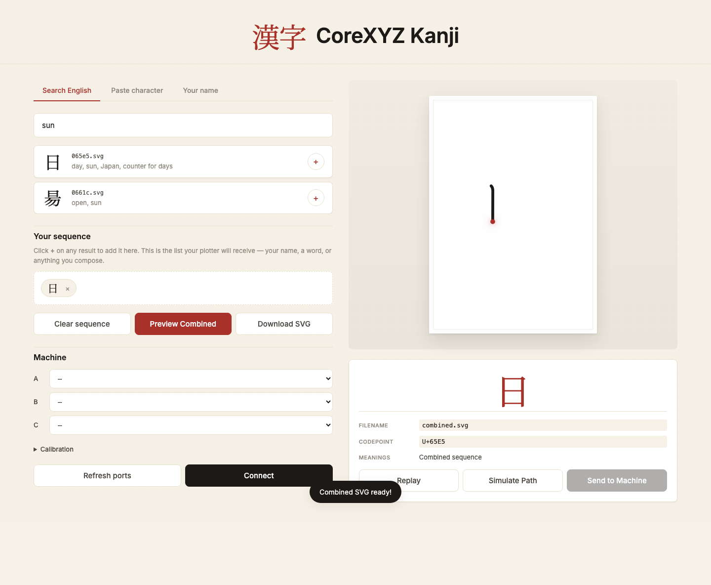
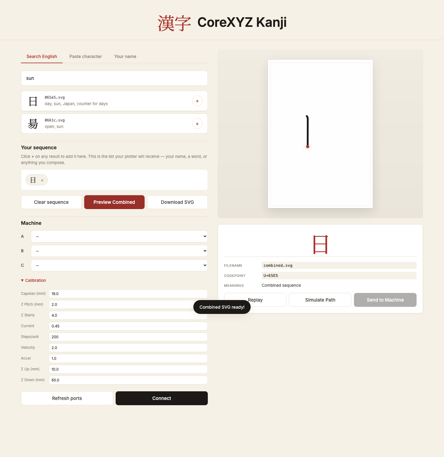
Here is the same flow in practice. First search, then combine SVGs:
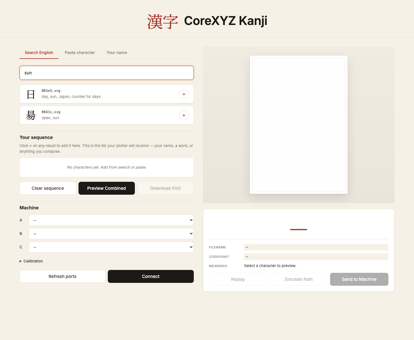
After combining a word into one SVG, the page previews the merged path.
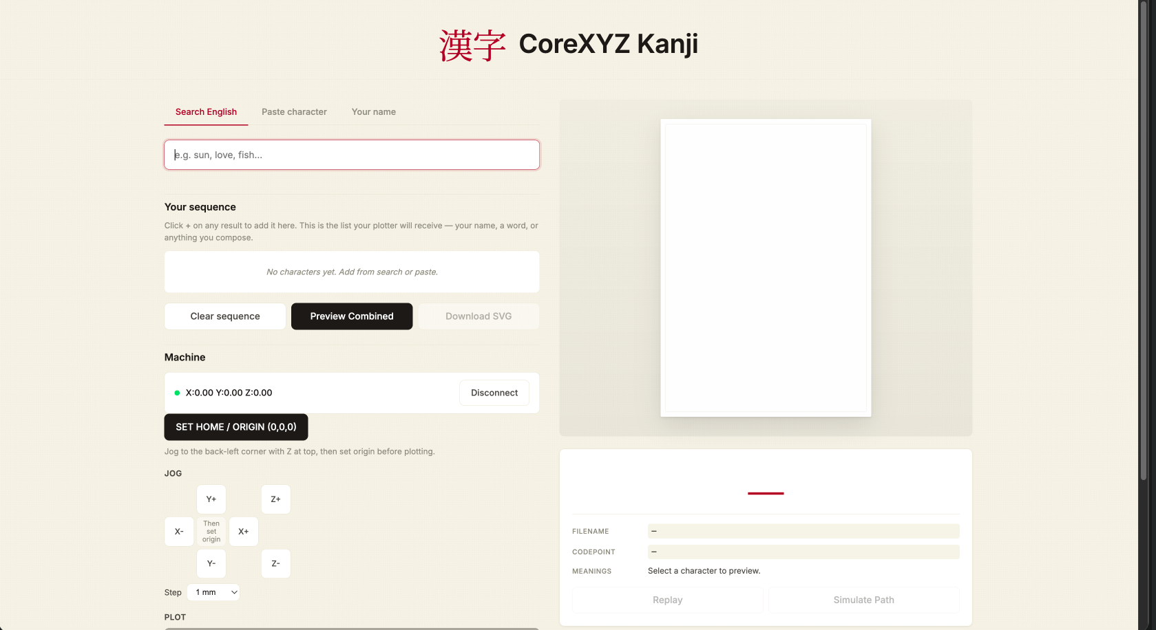
Then the machine panel exposes serial connect, calibration, and movement controls in the same app.
To run it on your own machine:
- Open Terminal in
frontend/. - Install dependencies:
pip install -r requirements.txt. - Start the server:
python3 app.py. - Open
127.0.0.1:5001in the browser.
Youssef also integrated a translation feature to the site with Claude that allows users to type a word in English and then choose from a selection of appropriate translations to be drawn.
Youssef created a function that could combine multiple Kanji (or in our demonstration cases, Katakana) characters into a single “file” vertically to have a multi-character name or phrase written on a single piece of paper.
Here’s Youssef’s documentation of how the frontend was created: Youssef’s Week 12 frontend section, and here is the frontend code: app.py and the backend: kanjiXYZ.py.
Drawing Kanji!
We had a great time testing out different characters on the machine. Here’s a video of one character being drawn start to finish (with a bonus crash at the end).
Troubles
We ran into a number of issues with the machine and how it behaved, only being able to fix or pinpoint some issues, while other issues were left unresolved or bodged to adapt to our goals for the week.
- The X (sometimes the Y) axis experienced some parasitic movement when we moved the Z axis exclusively. We tried to create some scripts to compensate for this motion, but ultimately we could not come up with a fix. We decided that this movement in the X axis did not impede our machine’s function, and even contributed a kind of “style” to the way our kanji were drawn. We believe this to have something to do with the slack compensation on the motor A and B vinyl cords not matching with the actual kinematics, but we couldn’t figure it out.
- Motors aggressively jumped upon initialization because the script dropped the steps_per_unit configuration and failed to overwrite stale target coordinates stored in the motor boards’ physical memory.
- Our limit switch safety loop worked too well and we had to ultimately remove them from the final project. Once the gantry pressed the switch, the software froze the motors, but when a new command was issued, it was sent in a multiple or corrupted manner and often gave us movement we did not want - which made it very difficult to code it to home itself if it kept losing track of where it was.
- The Z-axis was moving twice as far and twice as fast as it was supposed to. The cause was the script defaulted to a 2-start lead screw (4mm travel per rev), but we had a 4-start lead screw (8mm travel per rev).
- We mixed up our X and Y axis a lot, mostly due to the orientation we were working on the machine.
- The machine ignored the hooks and curves of some Kanji (like the second stroke in 口), drawing straight lines from the start to the end of the stroke. This was fixed by adding a
wait_for_move()at the end of the for loop for each stroke. The result is that the machine fully decelerates for each of the 15 segments, causing it to take more time to draw the Kanji, but the end result is still good enough! - The motors loudly skipped steps and crunched during long transit moves between strokes or when returning home. We couldn’t figure out why this was - we were operating the machine at pretty small velocity and acceleration values - certainly much smaller than what we saw in Quentin’s demonstration.
- The gantry would fall out of alignment a lot, requiring us to rebuild the machine.
- Kevlar threads would lose their tension if you crashed the motor too hard, requiring a reloop of the full circuit
- Lots of kevlar thread ended up getting cut by the tensioning bolt on the top cap, we realized that it was because a hidden nut found its way inside of the screw hole, adding unwanted friction to the screwing motion.
Creating the Video
Youssef drew and wrote out a storyboard for our 1 minute demonstration of the machine. We took turns saying a single line of dialogue on camera which could be paired up in editing software with B-roll of our machine in operation.
Youssef used Davinci Resolve to edit the video :D