Week04 | Embedded Programming
Group members
1. Objectives
- Study and analyze the RP2040 microcontroller datasheet to understand architecture, GPIO configuration, memory structure, and peripheral interfaces.
- Explore and compare different programming environments including MicroPython, CircuitPython, Thonny, and Arduino IDE.
- Perform practical soldering of components to prepare and verify the microcontroller board functionality.
- Develop and upload test programs using Arduino and MicroPython to validate input/output operations.
Thonny IDE Setup and MicroPython Configuration (RP2040)
For this assignment, I explored different development environments including MicroPython, CircuitPython, Arduino IDE, and mBlock. After testing, I decided to primarily use Thonny IDE for MicroPython development with the Raspberry Pi Pico (RP2040), as it provides a clean interface and direct serial interaction with the board.
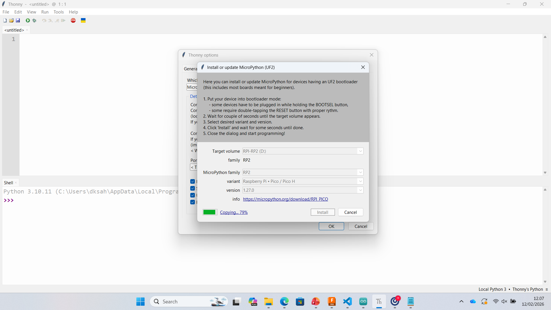
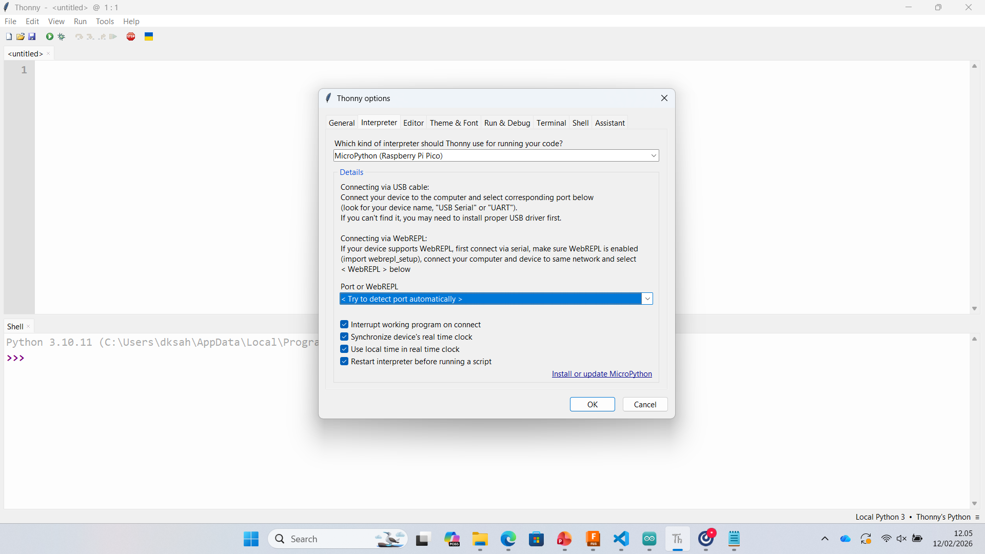
Step 1 – Installing / Updating MicroPython Firmware
To begin, I installed MicroPython firmware on the Raspberry Pi Pico using Thonny's built-in installer.
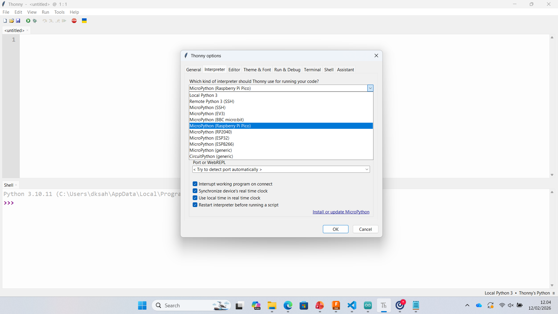
- Open Tools → Options → Interpreter
- Select MicroPython (Raspberry Pi Pico)
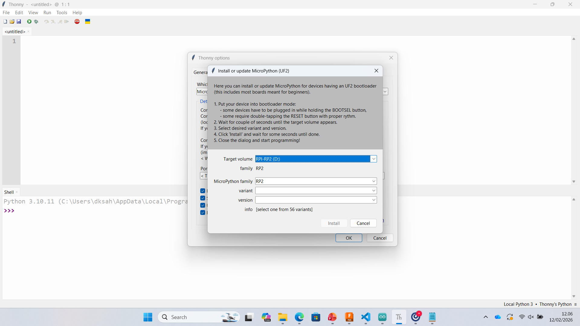
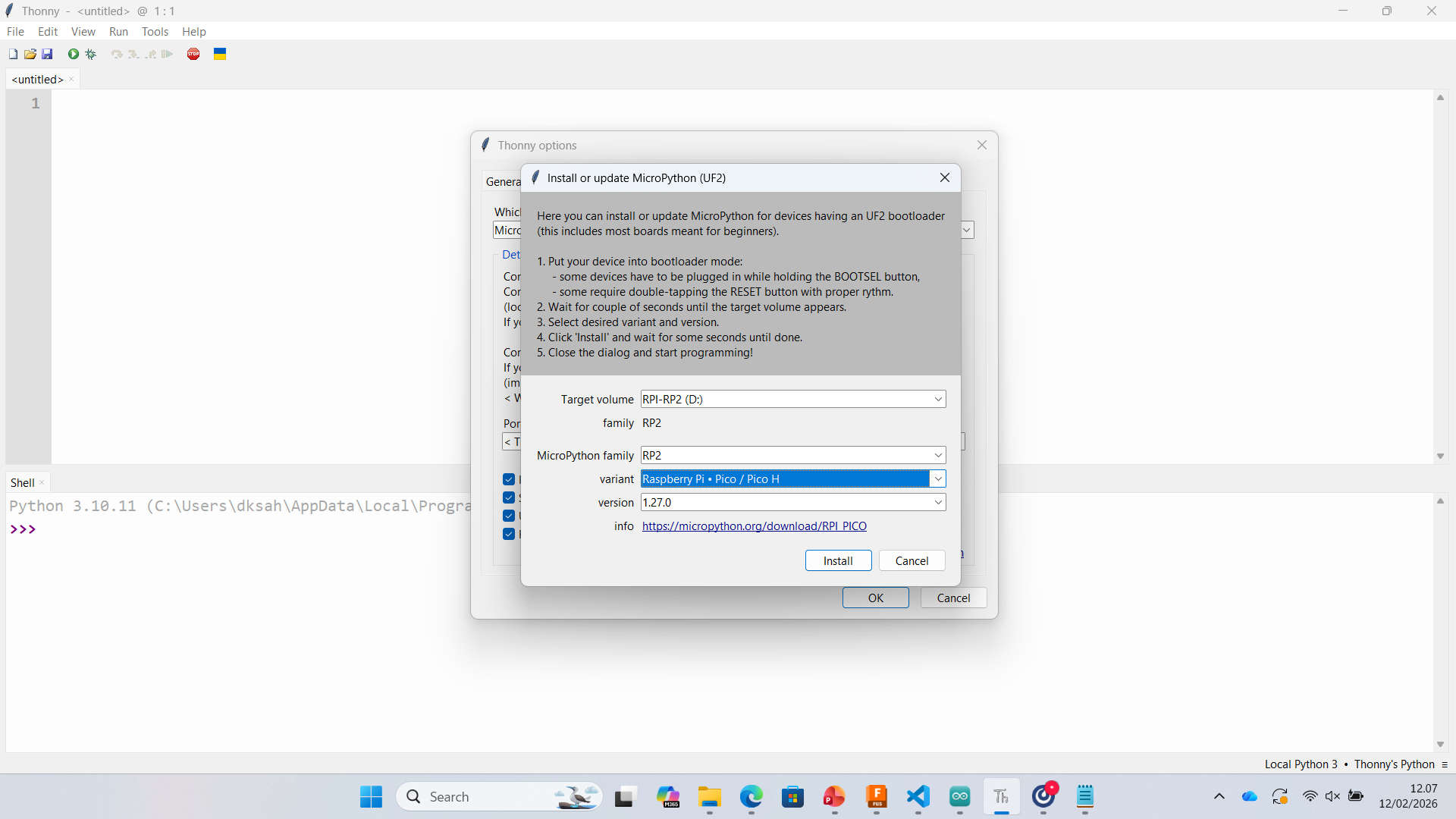
- Click Install or update MicroPython
- Put Pico into BOOTSEL mode and install firmware
 |
 |
 |
 |
The firmware was successfully installed (MicroPython v1.27.0 on RP2040).
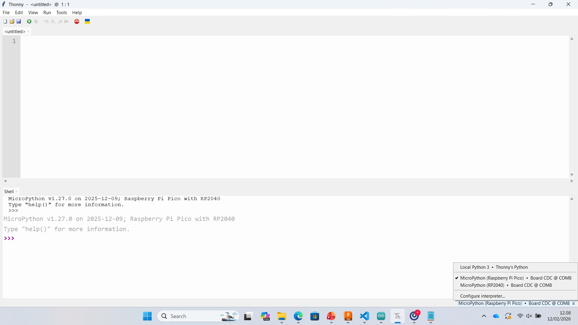
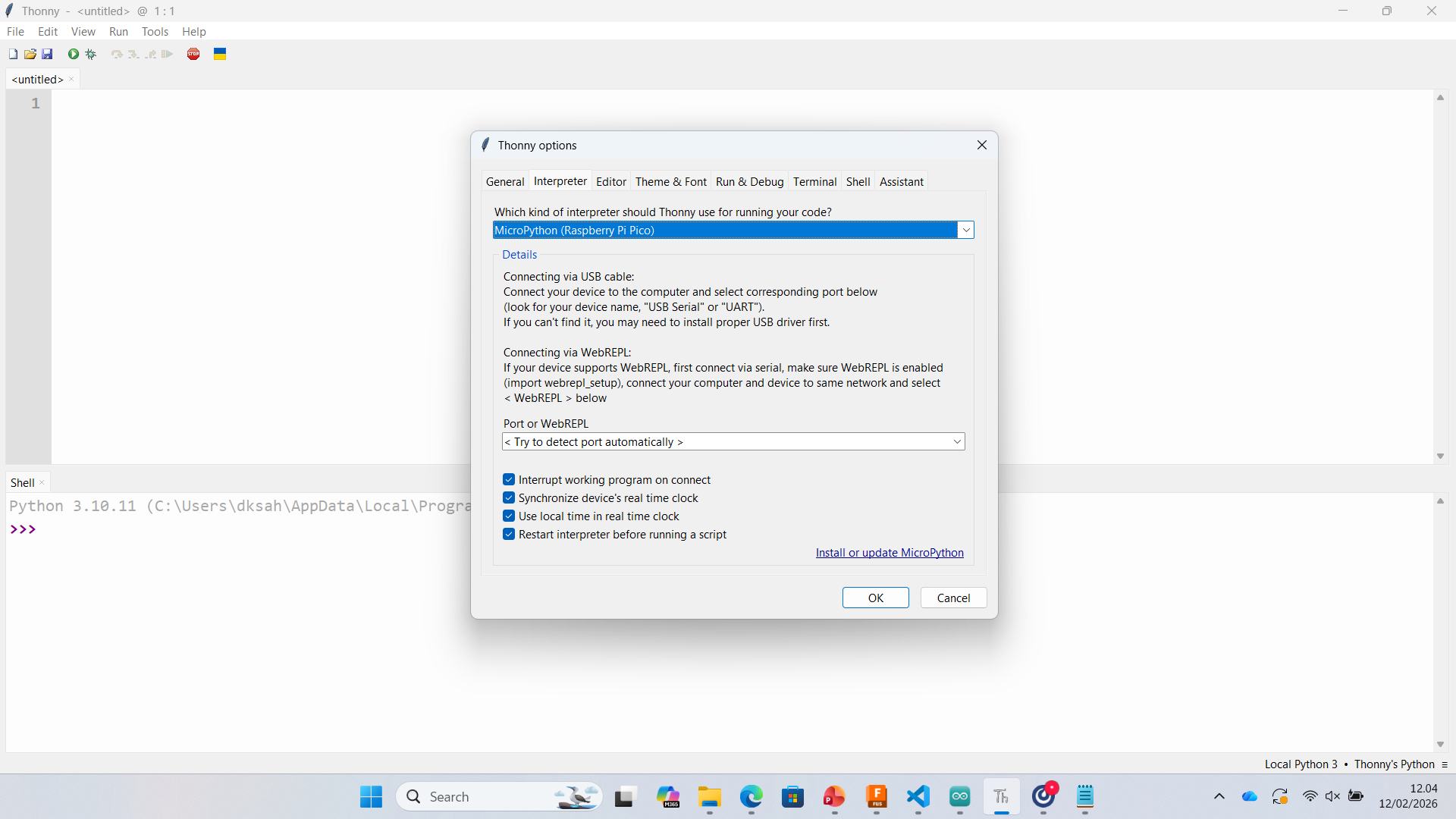
Step 2 – Configuring Interpreter
After installation, I configured the interpreter inside Thonny:
- Select MicroPython (Raspberry Pi Pico)
- Choose the correct COM port (Board CDC)
- Enable auto-detection
 |
 |
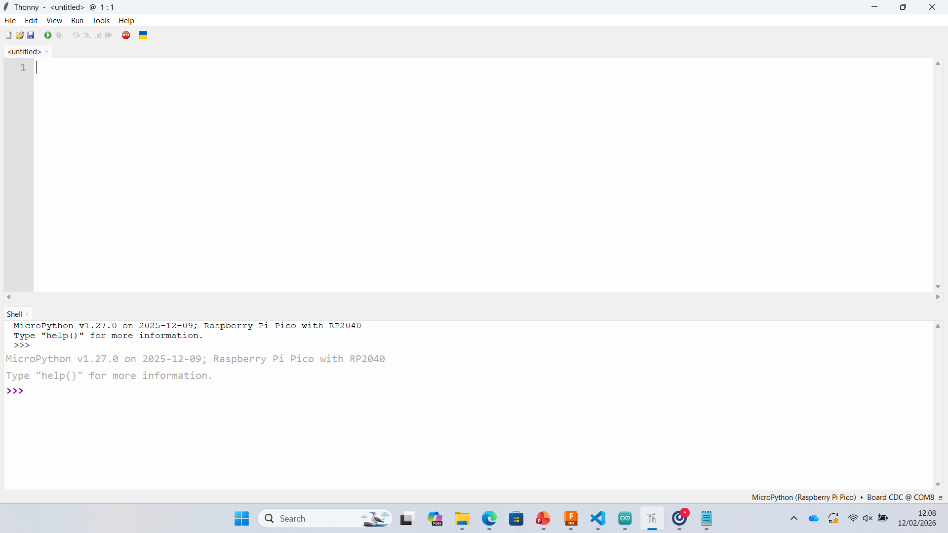
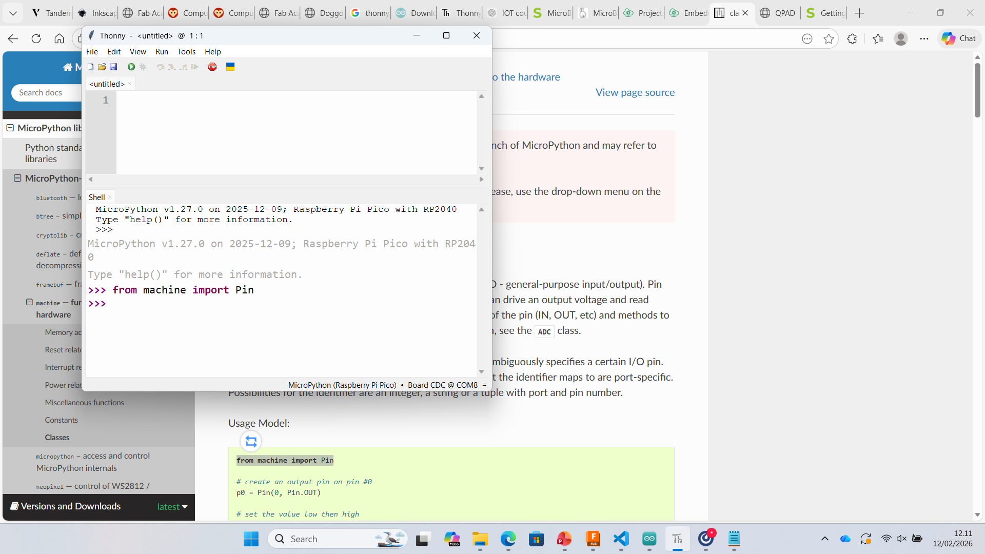
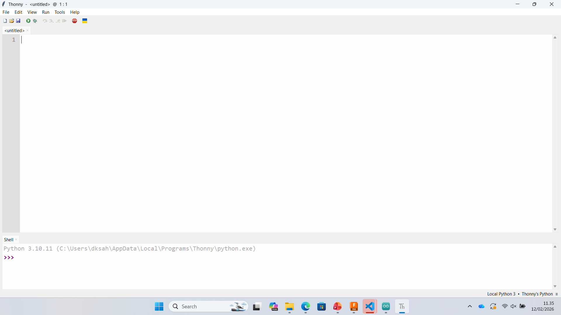
Step 3 – Accessing MicroPython Shell
Once connected, the MicroPython REPL (Shell) becomes active. This allows direct interaction with the microcontroller.
 |
 |
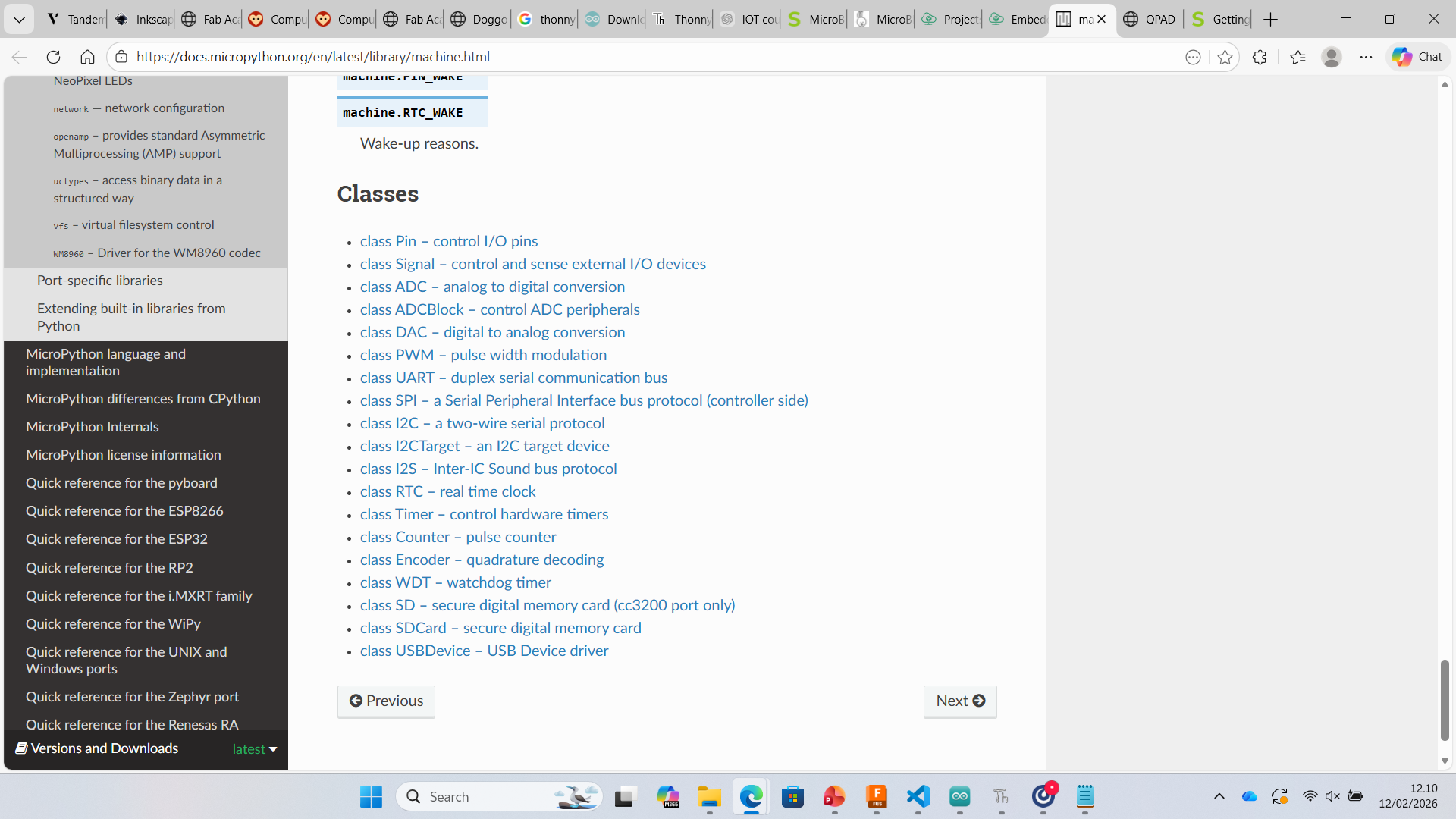
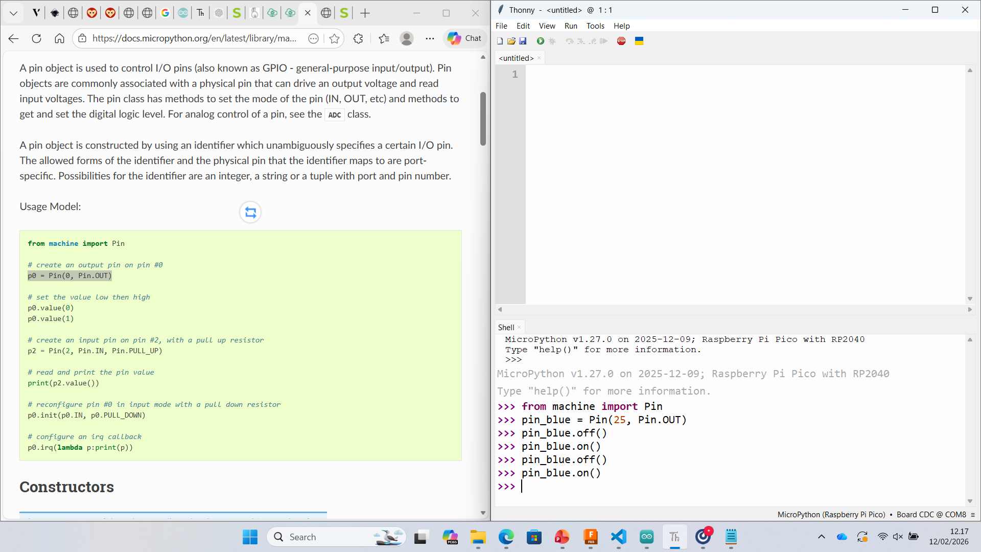
Step 4 – Testing GPIO using machine.Pin
I explored the machine library from MicroPython documentation. Specifically, I used the Pin class to control GPIO outputs.
 |
 |
Basic LED test on onboard LED (GPIO 25):
from machine import Pin
import time

led = Pin(25, Pin.OUT)

while True:
    led.on()
    time.sleep(1)
    led.off()
    time.sleep(1)
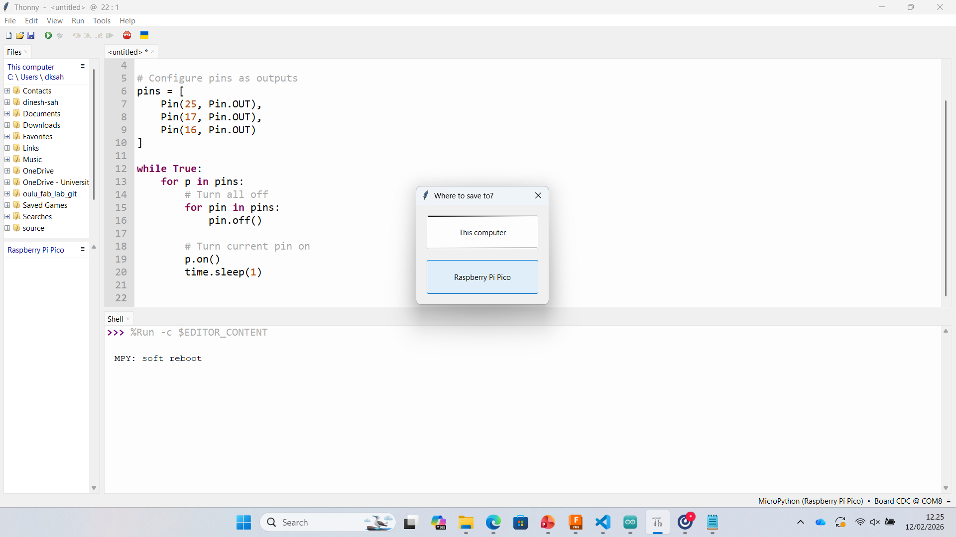
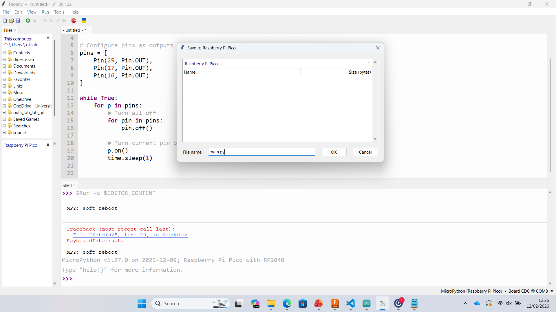
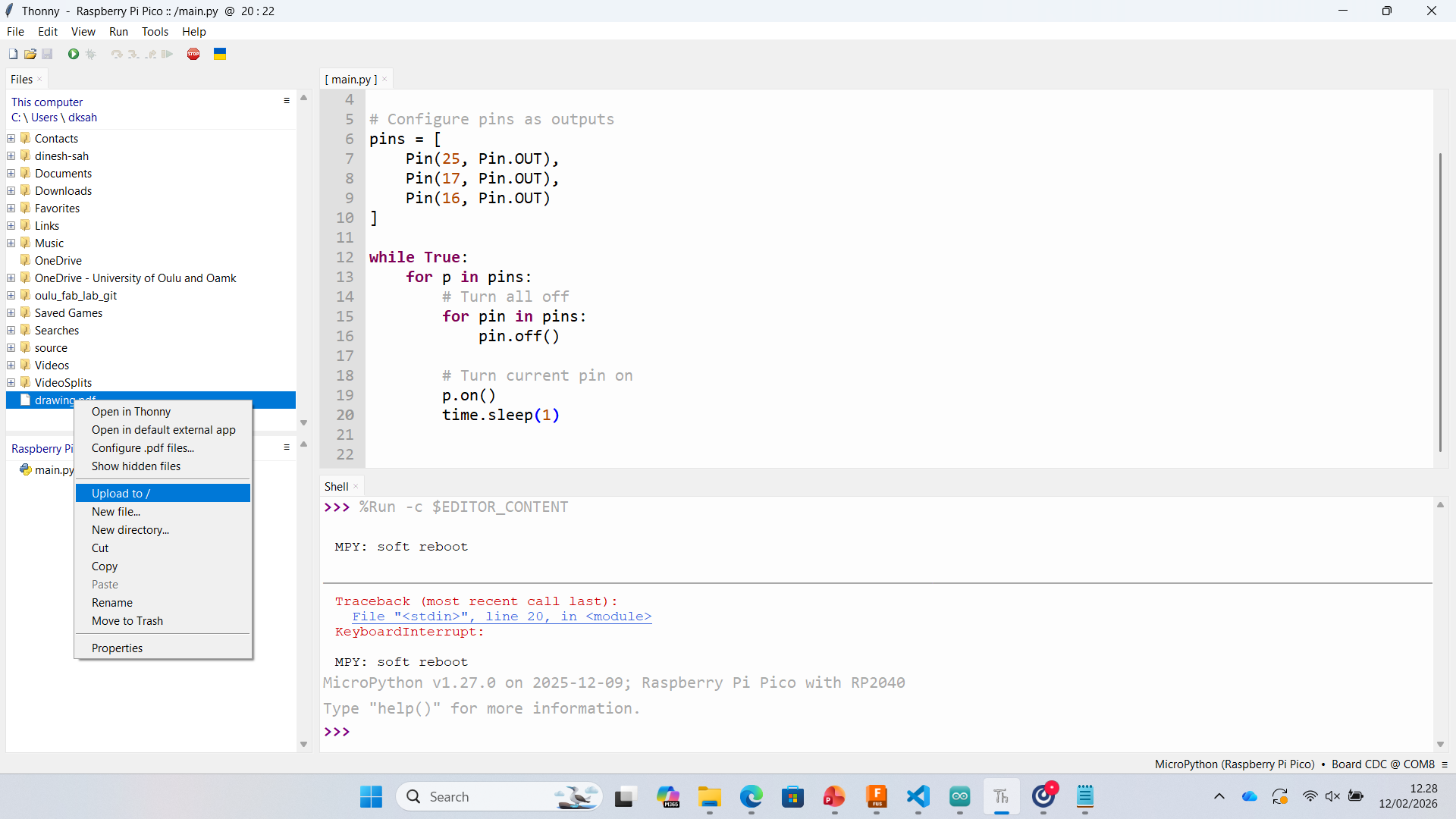
Step 5 – Saving Code to Pico (main.py)
To make the program run automatically after reset, I saved the script as main.py directly on the Raspberry Pi Pico.
 |
 |
 |
 |
Results
- Successfully installed MicroPython on RP2040
- Configured Thonny interpreter and COM port
- Tested onboard LED blinking
- Tested external LED (Neon light)
- Saved auto-run script as main.py
At this stage, I was able to successfully implement blinking LED and neon light control. Further experimentation with input devices and advanced peripherals will be continued in the next phase.
MicroBlocks – Programming Xiao RP2040
For this assignment, I explored MicroBlocks as a visual programming environment for the Xiao RP2040 board. MicroBlocks allows real-time interaction with the microcontroller and is useful for rapid testing of input and output devices.
Step 1 – USB Connection
The board was connected via USB. From the top-right menu, I selected Connect → connect (USB). The device appeared as Board CDC (COM7), confirming that the serial communication was working correctly.
.png)
Step 2 – Board Selection
After establishing the USB connection, I verified that the selected board was Xiao RP2040. This ensures correct pin mapping and compatibility with the RP2040 architecture.
.png)
Step 3 – Adding NeoPixel Library
To control the RGB LED (NeoPixel), I opened the library manager and added the NeoPixel (WS2812) library. This provides blocks for controlling RGB color values.
.png)
Step 4 – Writing the Program
I created a simple program using block-based logic:
- When started
- Attach 1 LED NeoPixel strip to pin 12
- Set all NeoPixels to a selected RGB color
This basic program allowed me to test output control of the NeoPixel LED.
.png)
Result
The NeoPixel LED responded correctly to the programmed instructions. This confirms:
- Successful USB communication
- Correct board configuration
- Working output device (NeoPixel)
Status: Completed ✅
Week 04 – Programming XIAO RP2040 (Arduino)
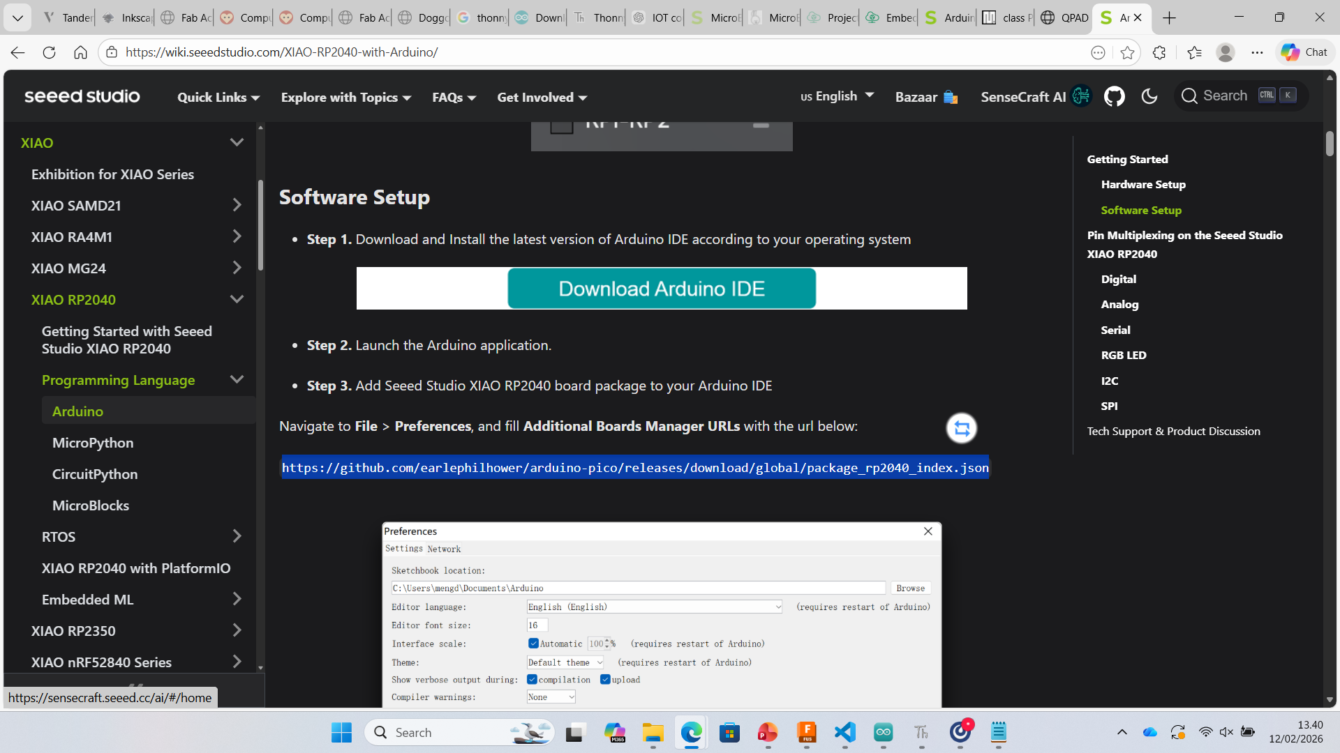
1. Installing Board Support
After installing Arduino IDE (v2.3.7), I added the RP2040 board support package using the Additional Boards Manager URL.
File → Preferences → Additional Board Manager URLs
https://github.com/earlephilhower/arduino-pico/releases/download/global/package_rp2040_index.json
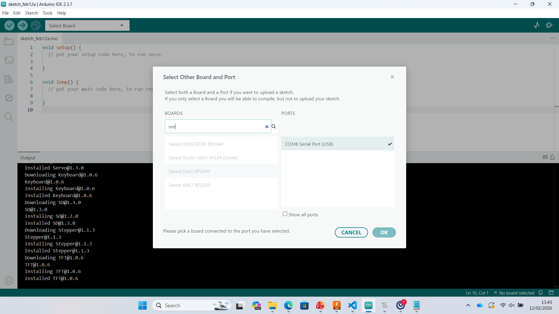
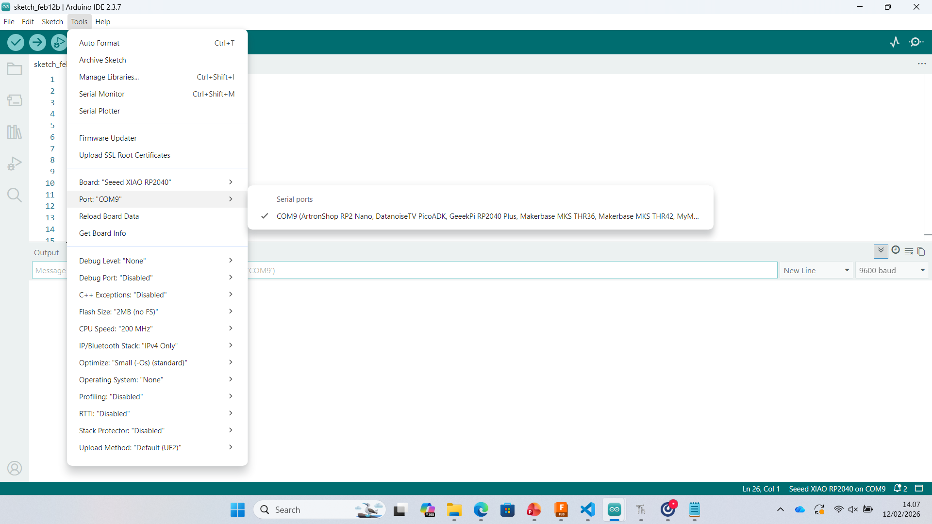
2. Selecting Board and COM Port
After installing the board package, I selected:
- Board: Seeed XIAO RP2040
- Port: COM9
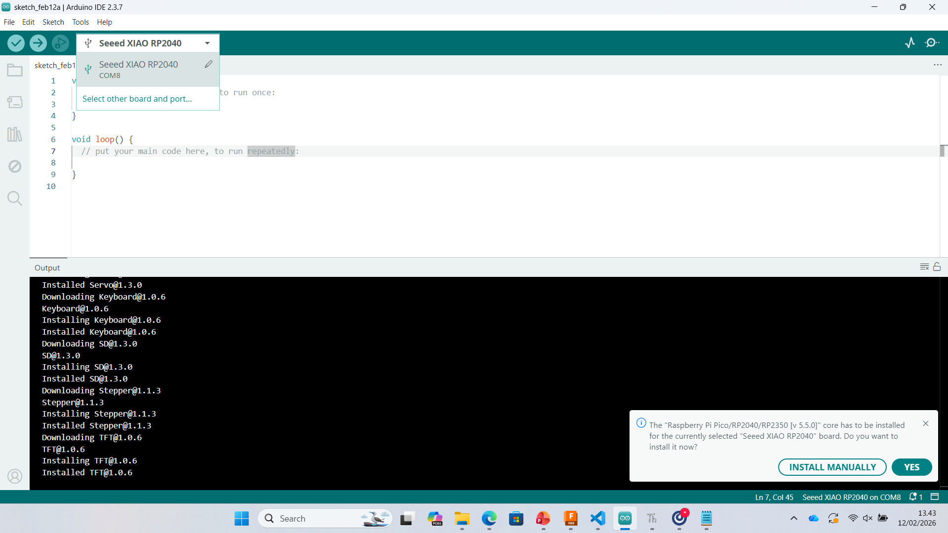
3. Installing Required Core
Arduino prompted installation of the Raspberry Pi Pico / RP2040 core. The installation was completed successfully.
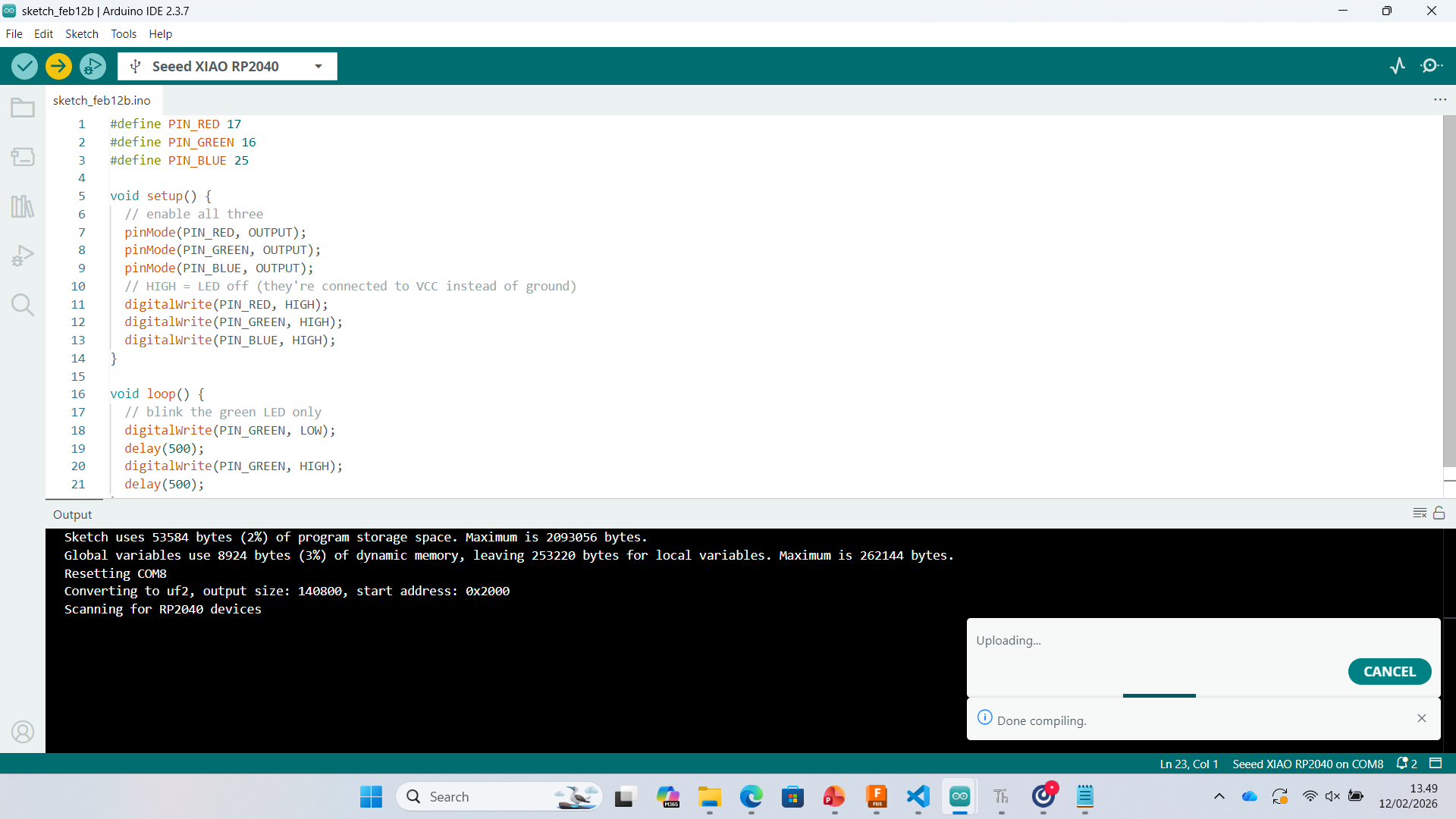
4. Blink Program (RGB LED Test)
I wrote a simple program to blink the green LED of the RGB LED.
#define PIN_RED 17
#define PIN_GREEN 16
#define PIN_BLUE 25

void setup() {
  pinMode(PIN_RED, OUTPUT);
  pinMode(PIN_GREEN, OUTPUT);
  pinMode(PIN_BLUE, OUTPUT);

  digitalWrite(PIN_RED, HIGH);
  digitalWrite(PIN_GREEN, HIGH);
  digitalWrite(PIN_BLUE, HIGH);
}

void loop() {
  digitalWrite(PIN_GREEN, LOW);
  delay(500);
  digitalWrite(PIN_GREEN, HIGH);
  delay(500);
}
Result: Green LED blinking successfully.
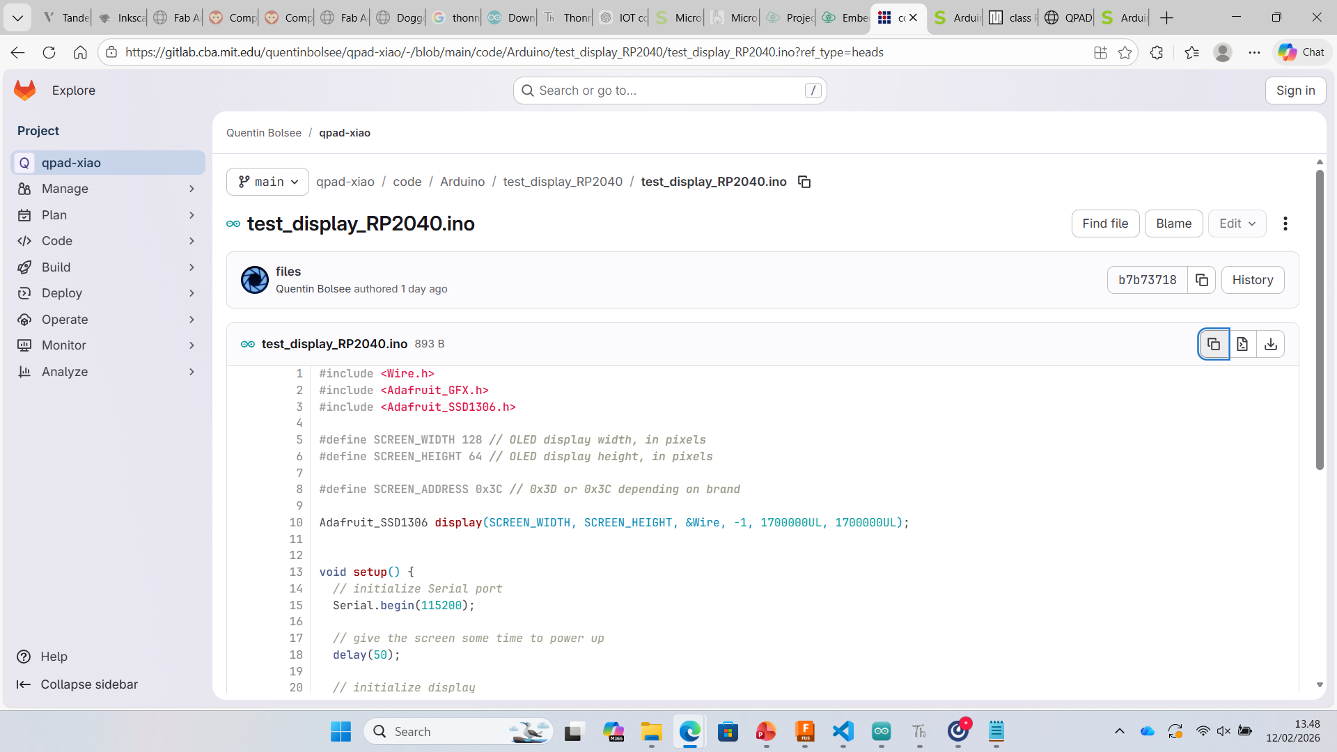
5. OLED Display Test (SSD1306)
I tested an SSD1306 OLED display using Adafruit libraries and I2C communication.
#include <Wire.h>
#include <Adafruit_GFX.h>
#include <Adafruit_SSD1306.h>

#define SCREEN_WIDTH 128
#define SCREEN_HEIGHT 64
#define SCREEN_ADDRESS 0x3C

Adafruit_SSD1306 display(SCREEN_WIDTH, SCREEN_HEIGHT, &Wire, -1);

void setup() {
  Serial.begin(115200);
  delay(50);

  display.begin(SSD1306_SWITCHCAPVCC, SCREEN_ADDRESS);
  display.clearDisplay();
  display.setTextSize(1);
  display.setTextColor(SSD1306_WHITE);
}

void loop() {
  display.clearDisplay();
  display.setCursor(28, 25);
  display.print("Hello world!");
  display.display();
}
Result: OLED successfully displayed "Hello world! (need attention)"
6. Compilation and Upload
The sketch compiled successfully. Memory usage and flashing process were verified during upload.
Learning Outcome
- Installed RP2040 board support in Arduino IDE
- Configured Board and COM Port correctly
- Programmed GPIO pins
- Controlled RGB LED
- Interfaced OLED display using I2C
- Understood compilation and upload workflow