Week06 | Electronics Design
Group members
Overview
For this week your task was to use the test equipment in your lab to observe the operation of an embedded microcontroller.
First using Arduino we generate a puls width modulation (PWM) signal from XIAO RP2040, and measure it with and also the PWM output was connected to a Servo motor.
Hardware and programming
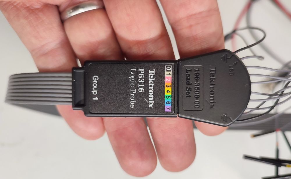
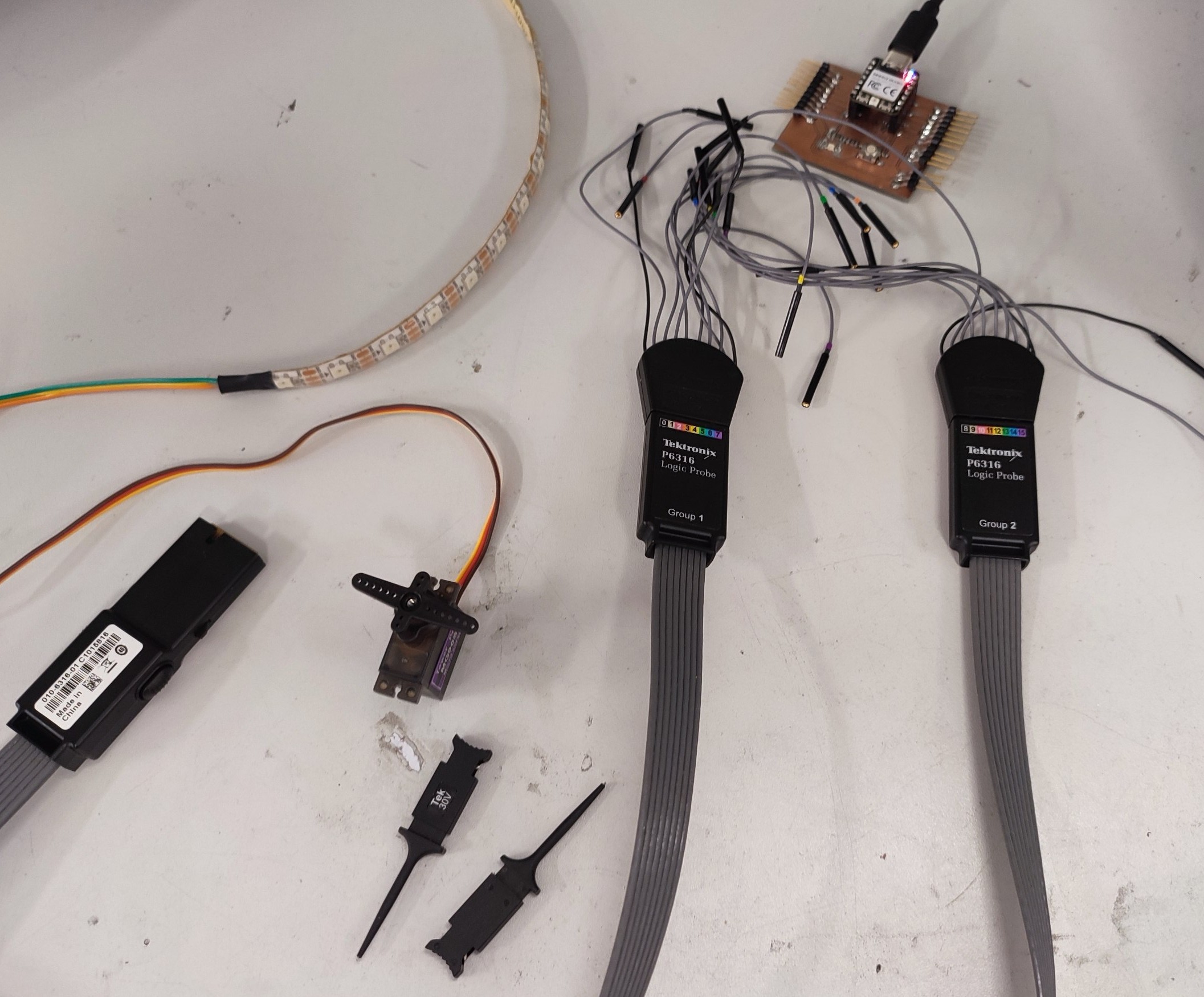
- Logic analyzer
- Servo Motor
- Microcontroller: XIAO RP2040
- Neopixel
- The PCB board which we made during week08, because We repeated this week measurement on 10.04.2026.
- Mixed signal oscilloscope
- Arduino IDE for programming
 |
 |
Neopixel
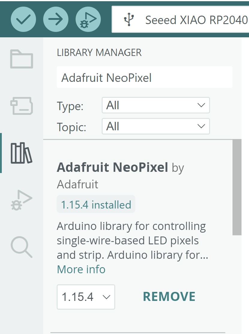
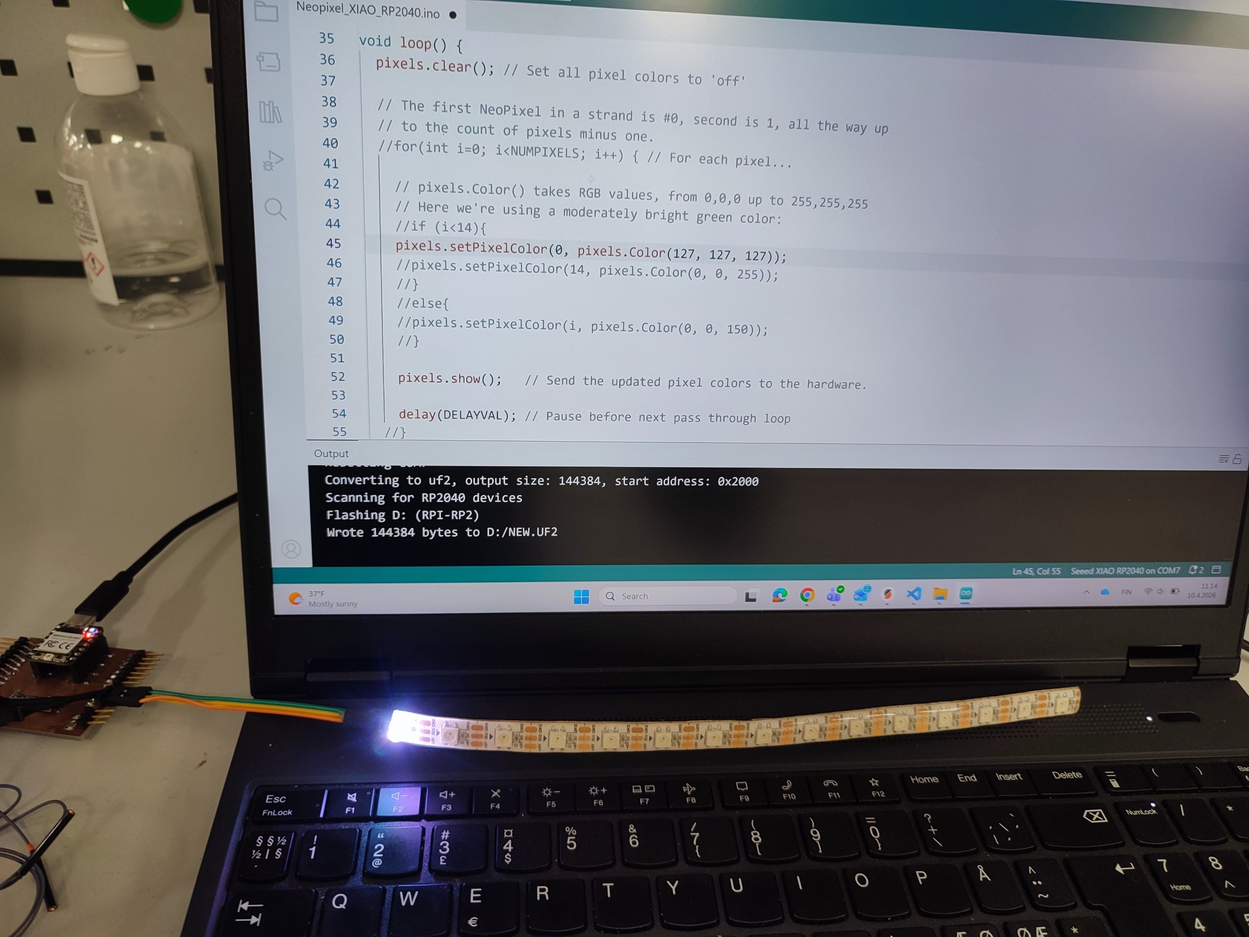
For programming we use Arduino, and started with installing Adafruit_NeoPixel library.
The Arduino code, we used:
// NeoPixel Ring simple sketch (c) 2013 Shae Erisson
// Released under the GPLv3 license to match the rest of the
// Adafruit NeoPixel library

#include <Adafruit_NeoPixel.h>
#ifdef __AVR__
 #include <avr/power.h> // Required for 16 MHz Adafruit Trinket
#endif

// Which pin on the Arduino is connected to the NeoPixels?
#define PIN        D9 // On Trinket or Gemma, suggest changing this to 1

// How many NeoPixels are attached to the Arduino?
#define NUMPIXELS 15 // Popular NeoPixel ring size

// When setting up the NeoPixel library, we tell it how many pixels,
// and which pin to use to send signals. Note that for older NeoPixel
// strips you might need to change the third parameter -- see the
// strandtest example for more information on possible values.
Adafruit_NeoPixel pixels(NUMPIXELS, PIN, NEO_GRB + NEO_KHZ800);

#define DELAYVAL 500 // Time (in milliseconds) to pause between pixels

void setup() {
  // These lines are specifically to support the Adafruit Trinket 5V 16 MHz.
  // Any other board, you can remove this part (but no harm leaving it):
#if defined(__AVR_ATtiny85__) && (F_CPU == 16000000)
  clock_prescale_set(clock_div_1);
#endif
  // END of Trinket-specific code.

  pixels.begin(); // INITIALIZE NeoPixel strip object (REQUIRED)
}

void loop() {
  pixels.clear(); // Set all pixel colors to 'off'

  // The first NeoPixel in a strand is #0, second is 1, all the way up
  // to the count of pixels minus one.
  //for(int i=0; i<NUMPIXELS; i++) { // For each pixel...

    // pixels.Color() takes RGB values, from 0,0,0 up to 255,255,255
    // Here we're using a moderately bright green color:
    //if (i<14){
    pixels.setPixelColor(0, pixels.Color(0, 127, 0));
    pixels.setPixelColor(12, pixels.Color(0, 0, 127));
    //}
    //else{
    //pixels.setPixelColor(i, pixels.Color(0, 0, 150));
    //}

    pixels.show();   // Send the updated pixel colors to the hardware.

    delay(DELAYVAL); // Pause before next pass through loop
  //}
}
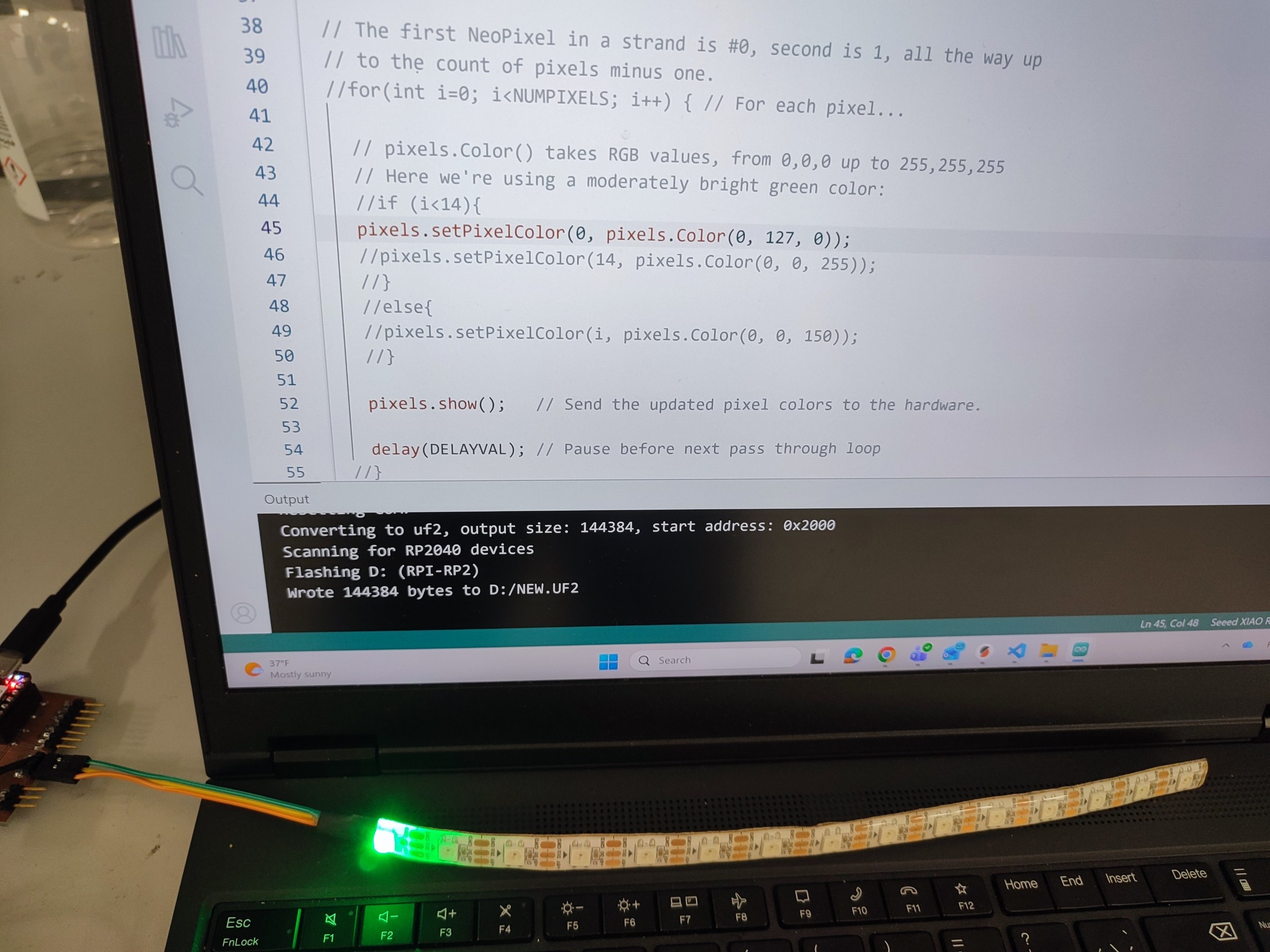
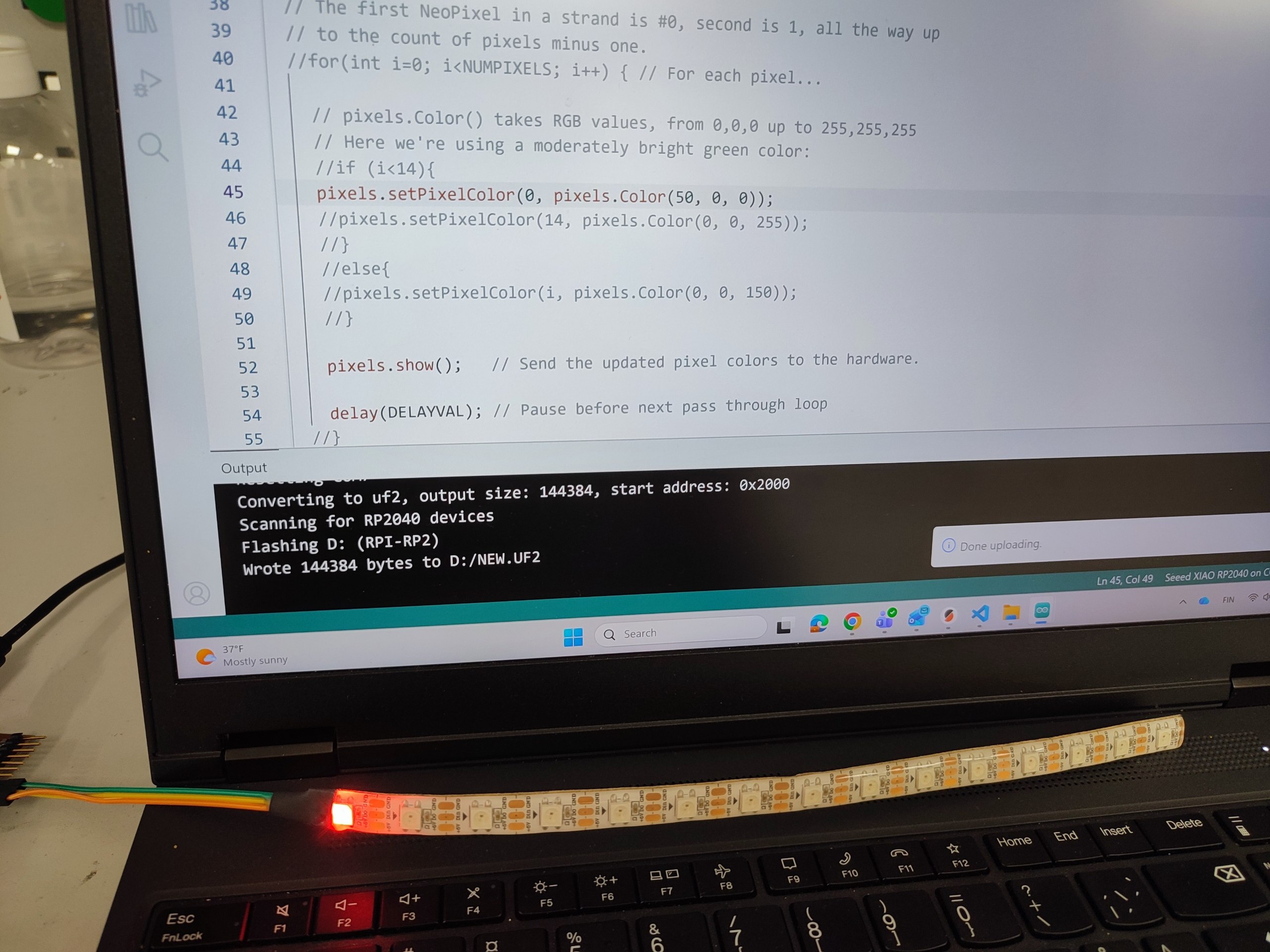
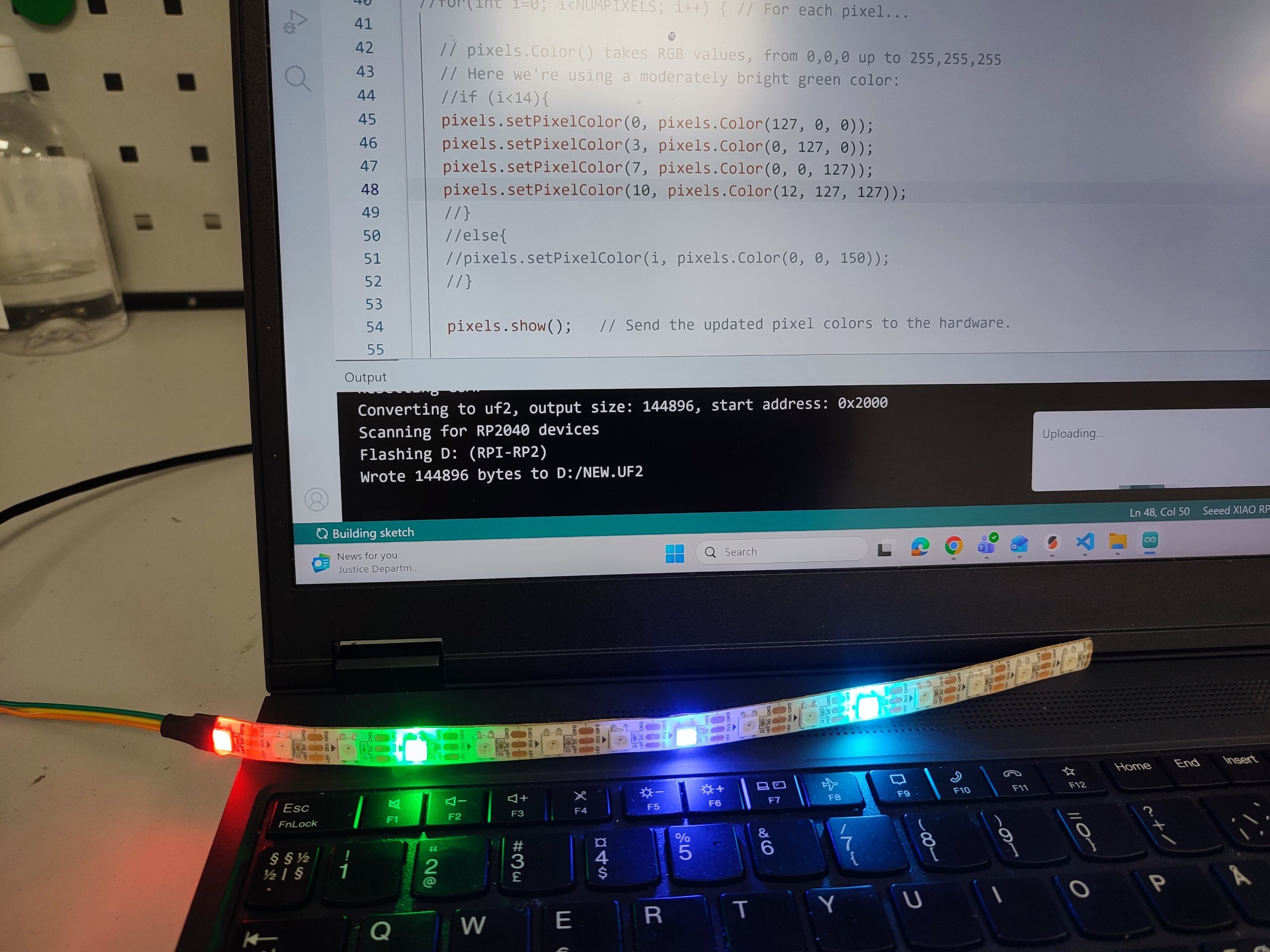
We controlled which pixel and its color.
At first, we send just the data to turn on the first LED.
pixels.setPixelColor(0, pixels.Color(0, 127, 0));
 |
 |
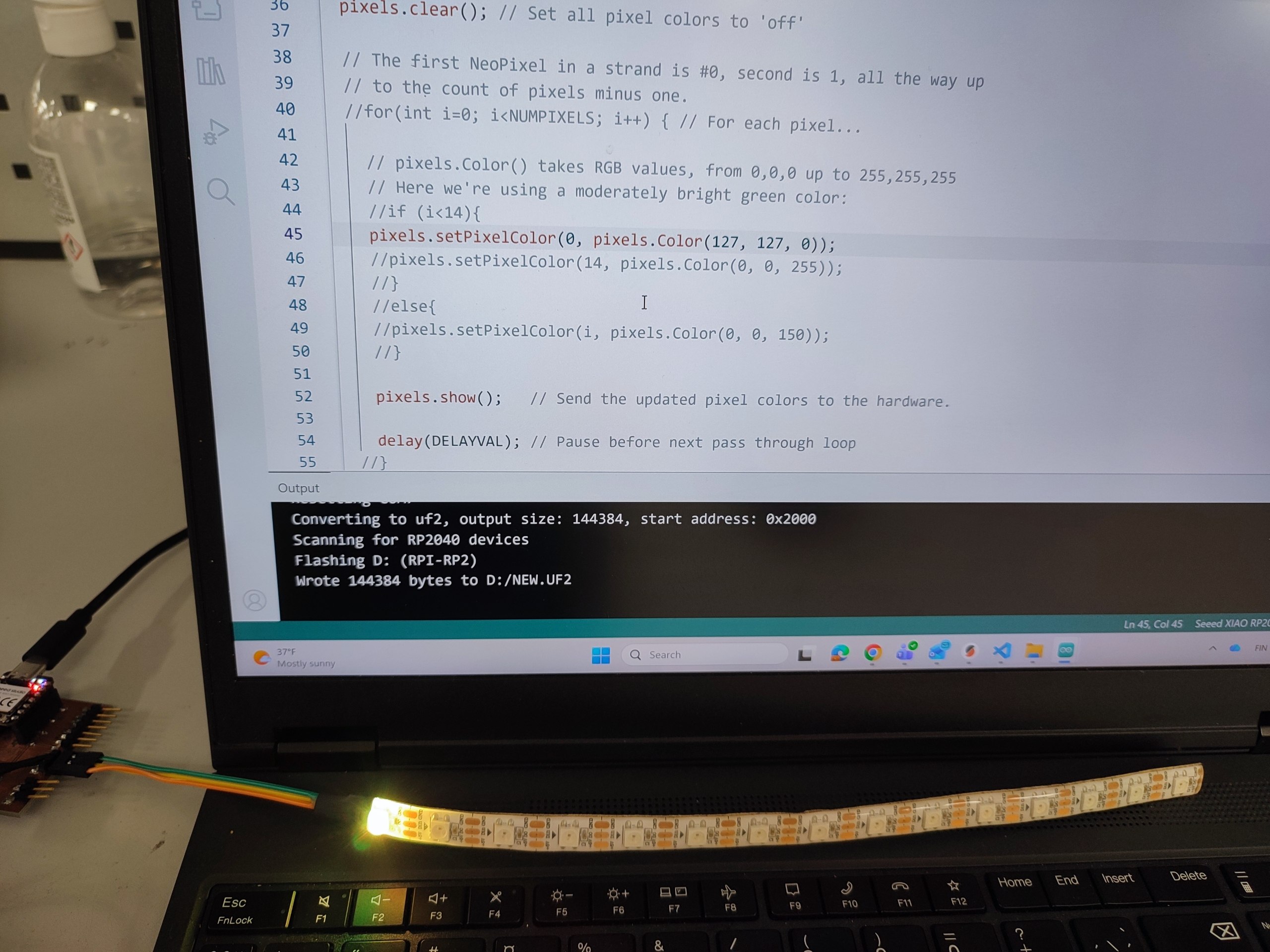
pixels.setPixelColor(0, pixels.Color(127, 127, 0));
 |
 |
pixels.setPixelColor(0, pixels.Color(127, 127, 127));
 |
 |
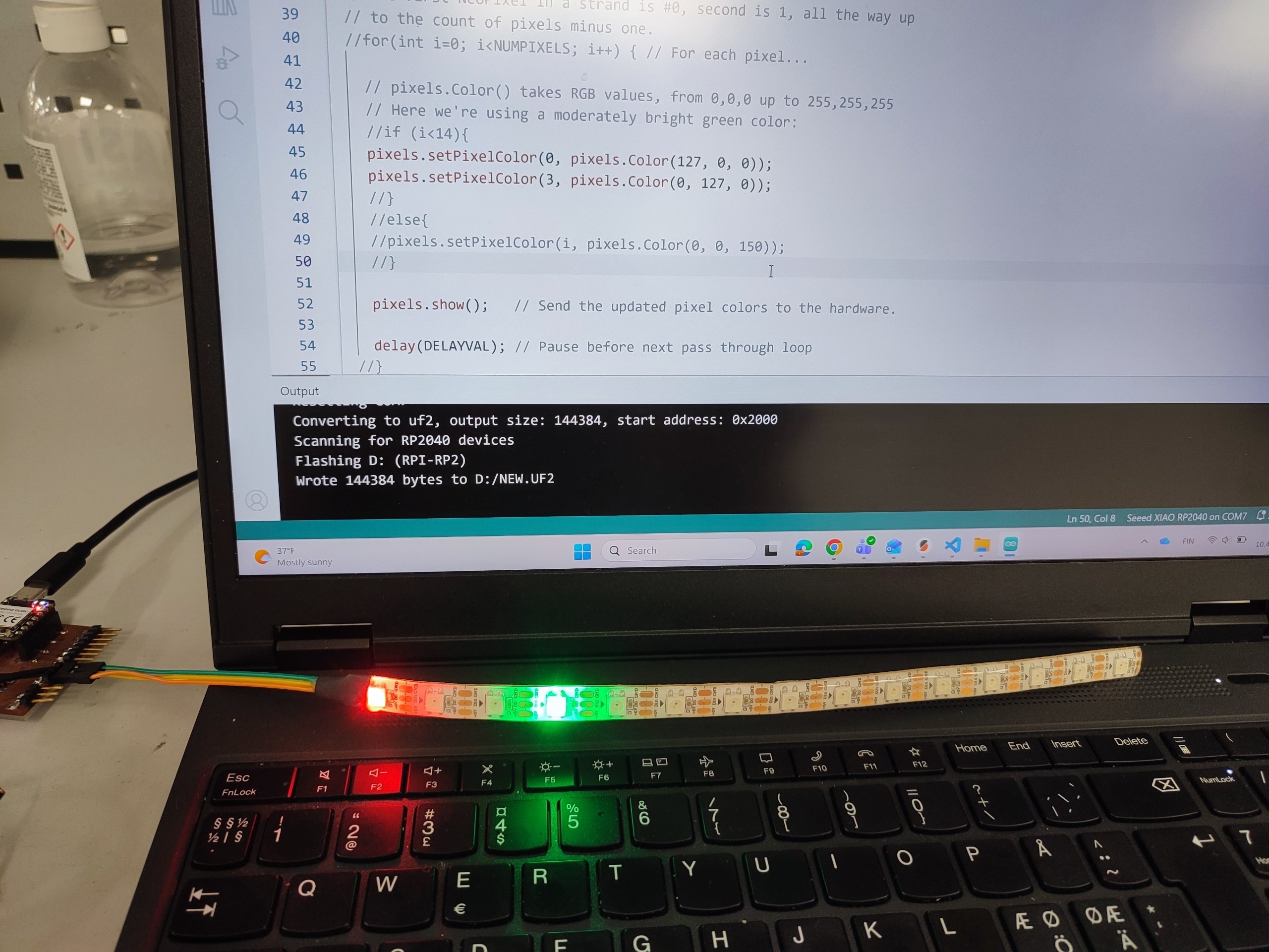
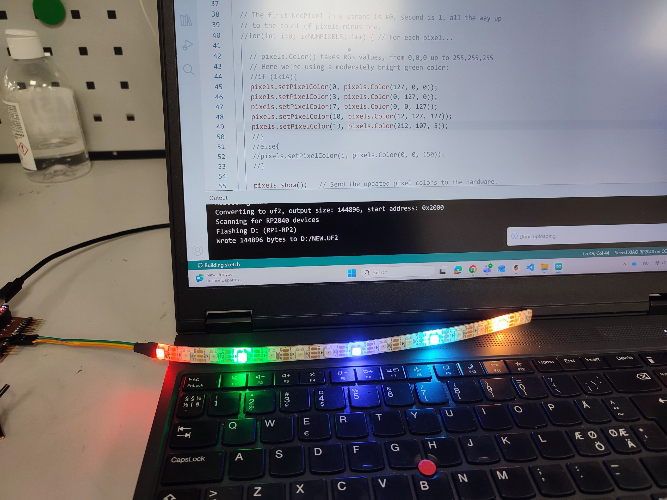
We managed to control pixels in different place.
 |
 |
 |
 |
PWM Setup and Servo & LED
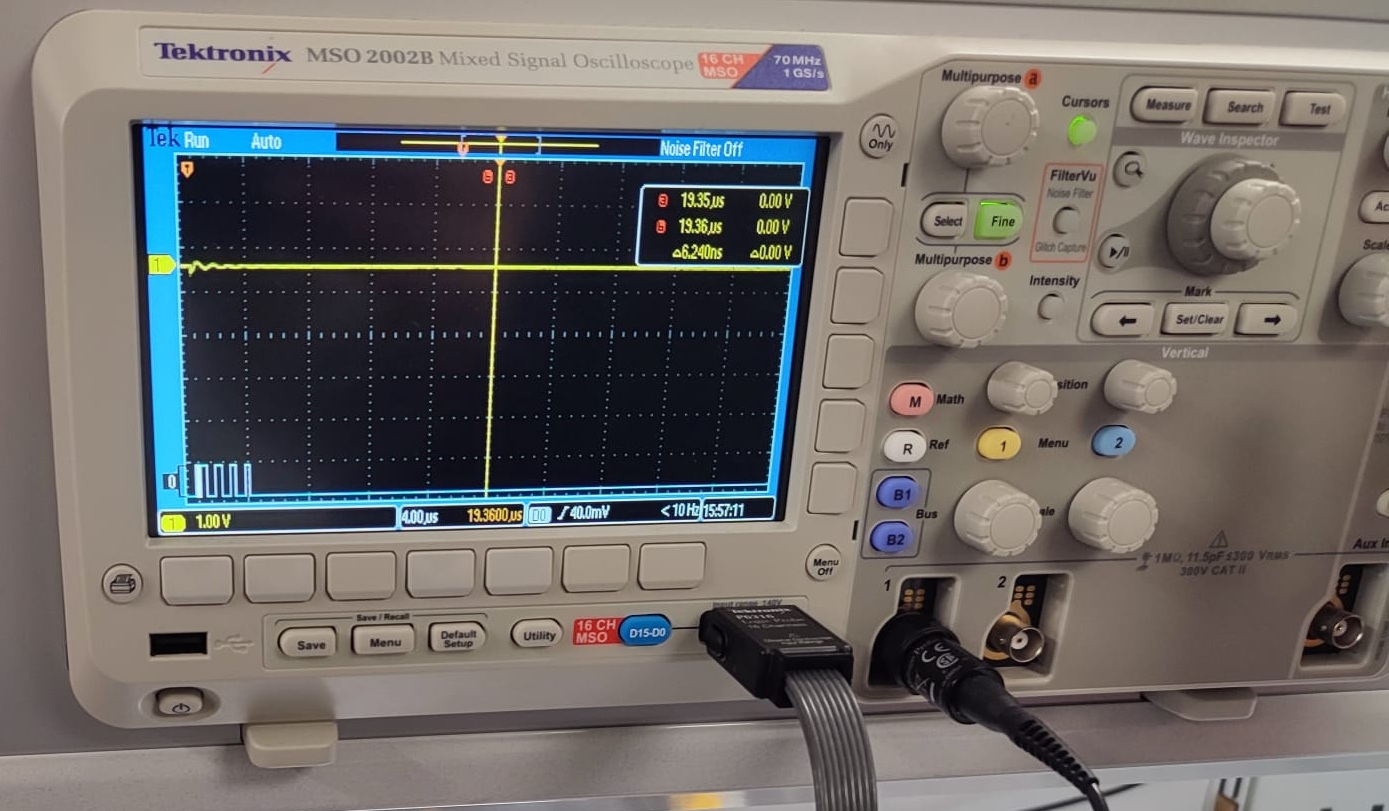
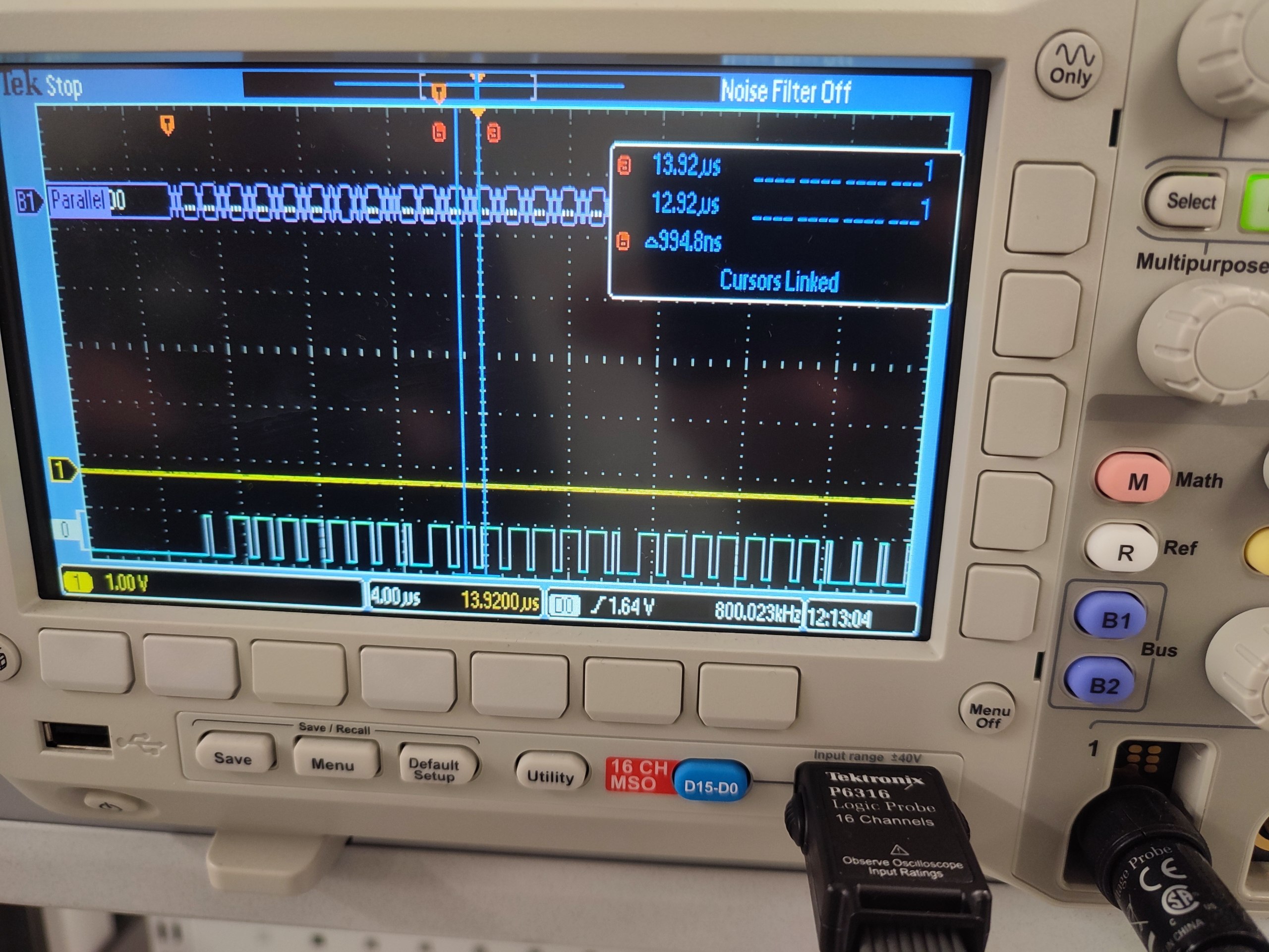
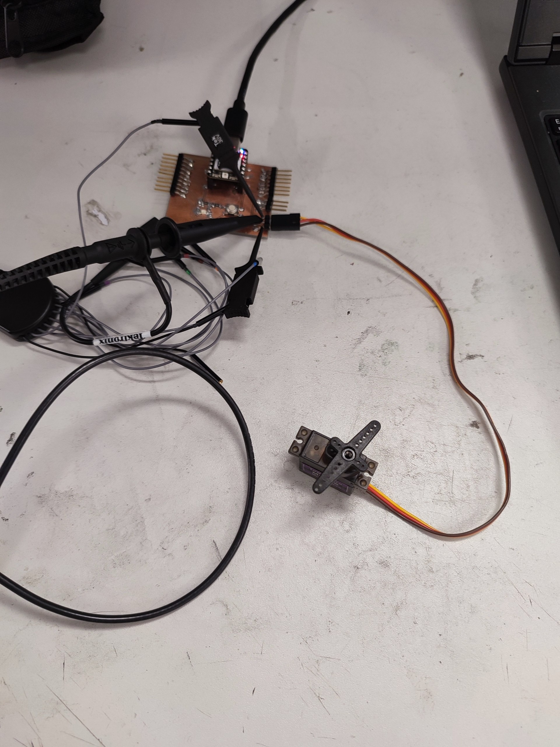
We measured the PWM signal using *Mixed signal analyzer and we saw the signal PMW behavior and its operated on a servo motor.
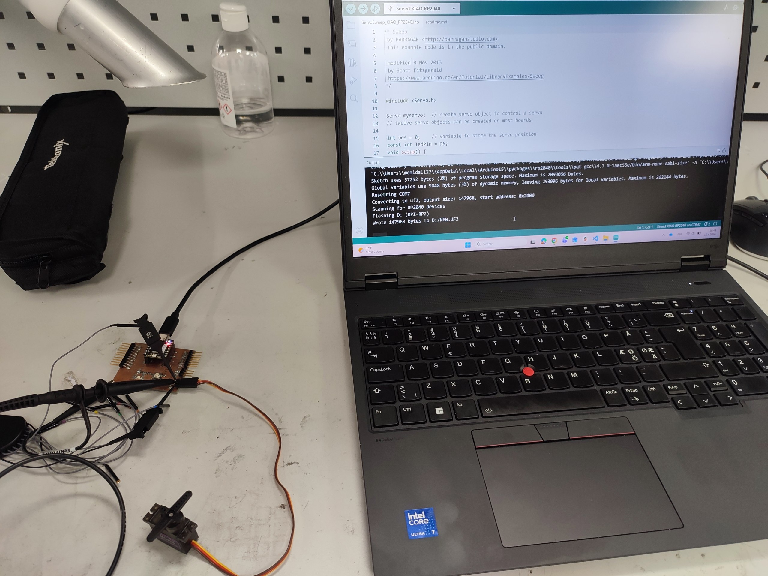
PMW test setup:
 |
 |
We used this following Arduino code for PMW test. Before that, we installed Servo library. In the code, we define the output pins as a data which is D8 for RP2040, and D6 for LED on the board. The degree of movement and delay time to turn back, can be defined in the code.
/* Sweep
 by BARRAGAN <http://barraganstudio.com>
 This example code is in the public domain.

 modified 8 Nov 2013
 by Scott Fitzgerald
 https://www.arduino.cc/en/Tutorial/LibraryExamples/Sweep
*/

#include <Servo.h>

Servo myservo;  // create servo object to control a servo
// twelve servo objects can be created on most boards

int pos = 0;    // variable to store the servo position
const int ledPin = D6;
void setup() {
  myservo.attach(D8);  // attaches the servo on pin 9 to the servo object
}

void loop() {
  for (pos = 0; pos <= 180; pos += 1) { // goes from 0 degrees to 180 degrees
    // in steps of 1 degree
    myservo.write(pos);              // tell servo to go to position in variable 'pos'
    delay(15);                       // waits 15 ms for the servo to reach the position
    analogWrite(ledPin, pos);
  }
  for (pos = 180; pos >= 0; pos -= 1) { // goes from 180 degrees to 0 degrees
    myservo.write(pos);              // tell servo to go to position in variable 'pos'
    delay(15);                       // waits 15 ms for the servo to reach the position
    analogWrite(ledPin, pos);
  }
}
-
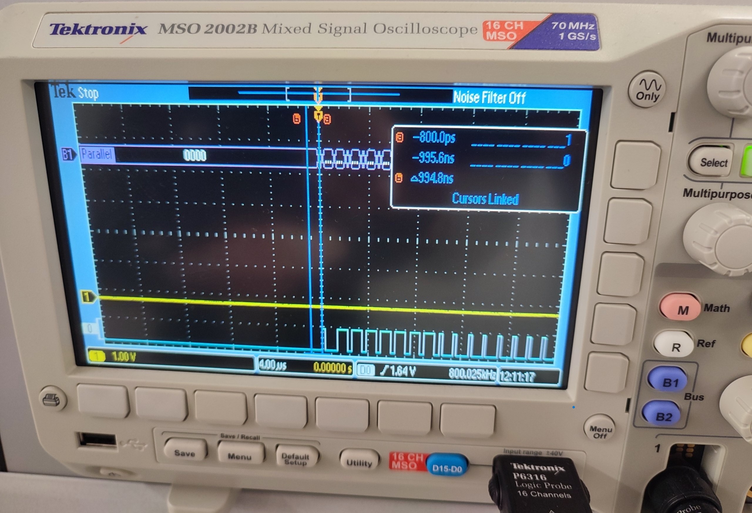
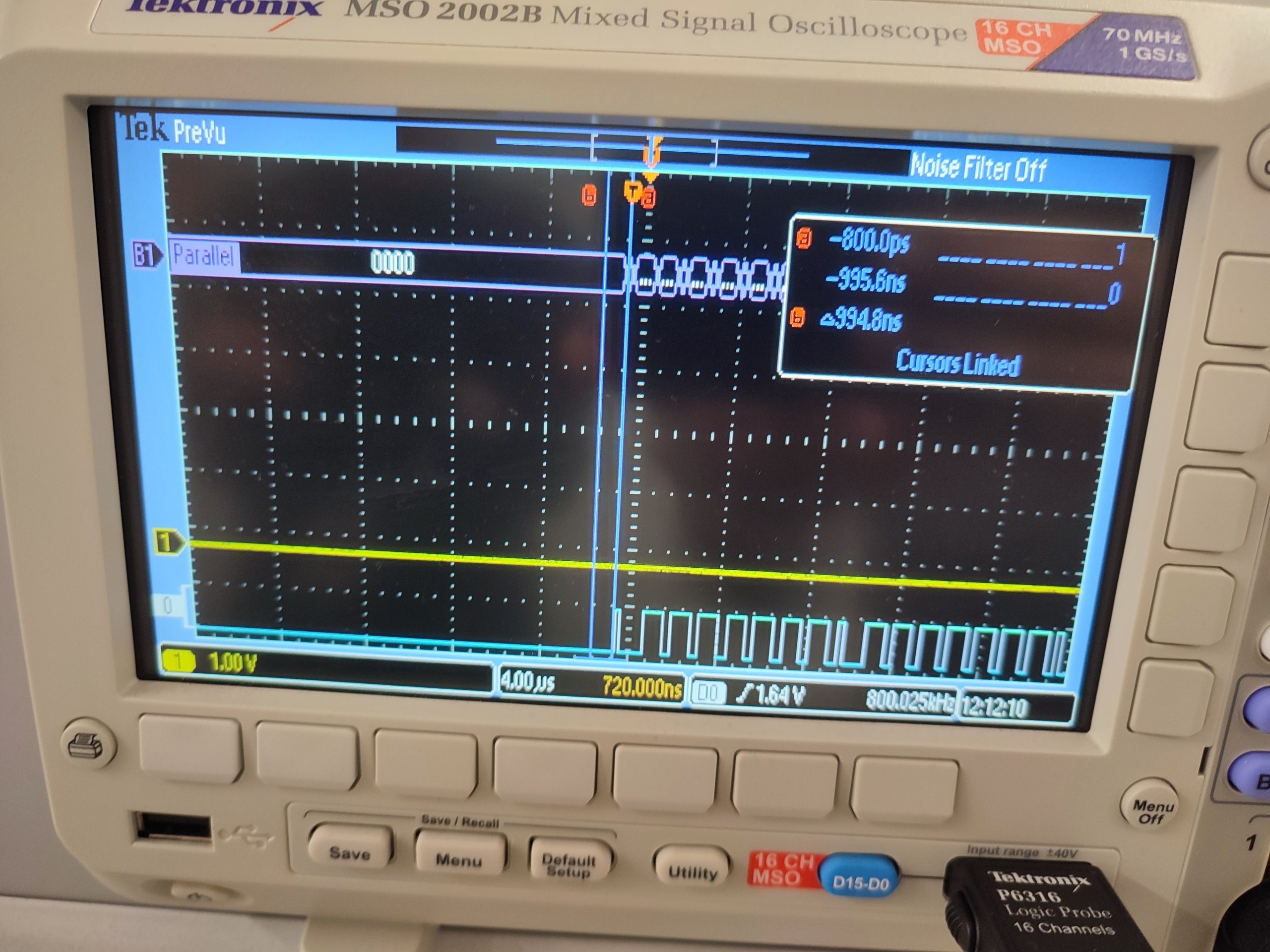
Analog probe (yellow line): voltage amplitude, rise time, we observed that the signal not exactly like square wave.
-
Digital probe (blue line): showed logic levels (high and low).
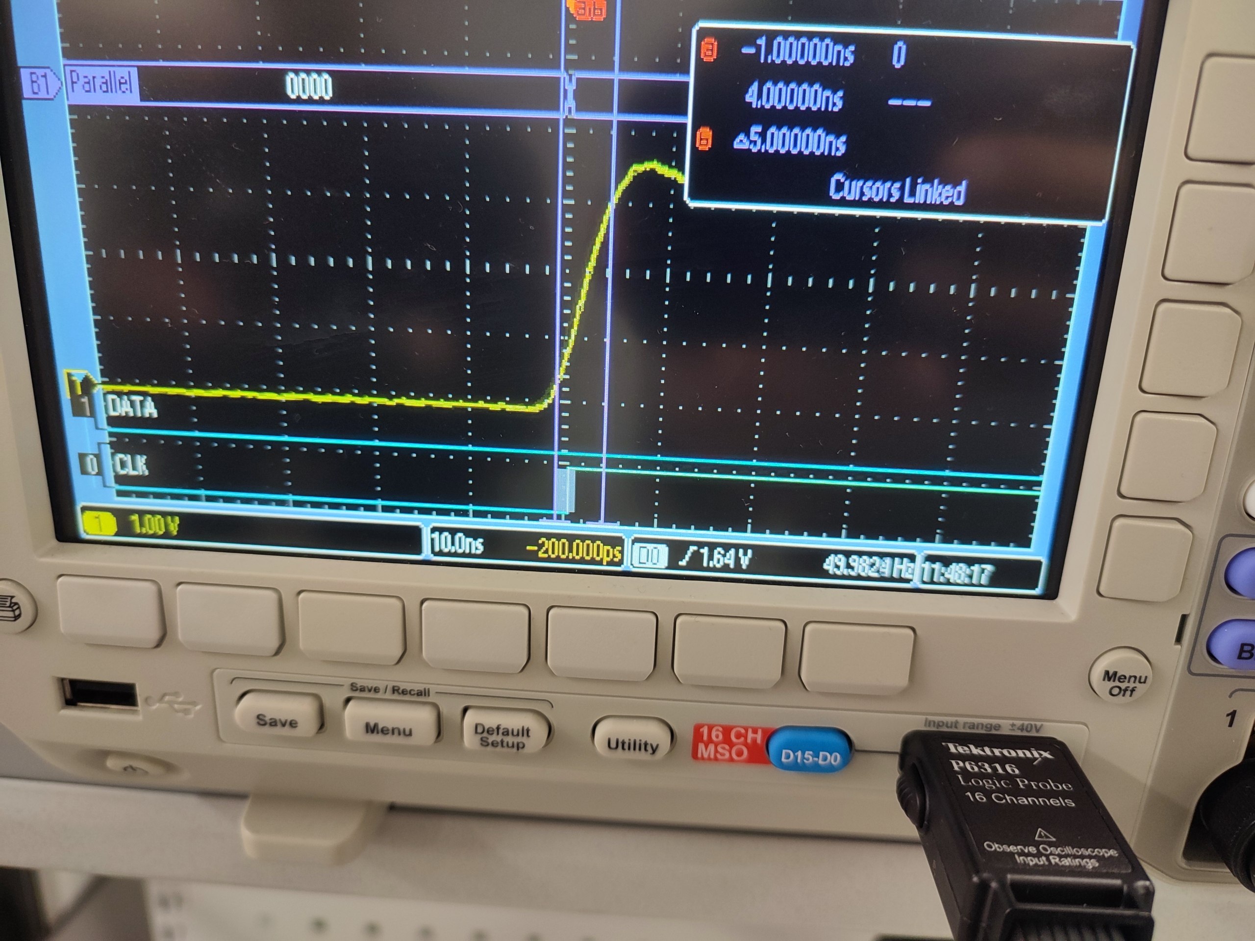
This measurement demonstrates how abstract serial data (e.g., characters or bytes) is physically represented as timed voltage transitions on a single communication line.
-