Group Assignment: CNC Machine Characterization
Group Assignment Objectives
The objective of this group assignment was to characterize the CNC machine available at Fab Lab Winam. The characterization involved:
- Completing the CNC machine safety training.
- Understanding the machine specifications and safety features.
- Testing spindle runout and machine alignment.
- Testing different workholding/fixturing methods.
- Evaluating suitable speeds and feeds for the selected material and tool.
- Testing different CNC toolpaths.
- Understanding the complete workflow from CAD design to CNC machining.
1. Machine Description
The machine used for this assignment is a Scientific Forest CNC Router located at Fab Lab Winam. It is a 3-axis CNC router designed for machining sheet materials such as plywood, MDF, acrylic, and other non-ferrous materials.
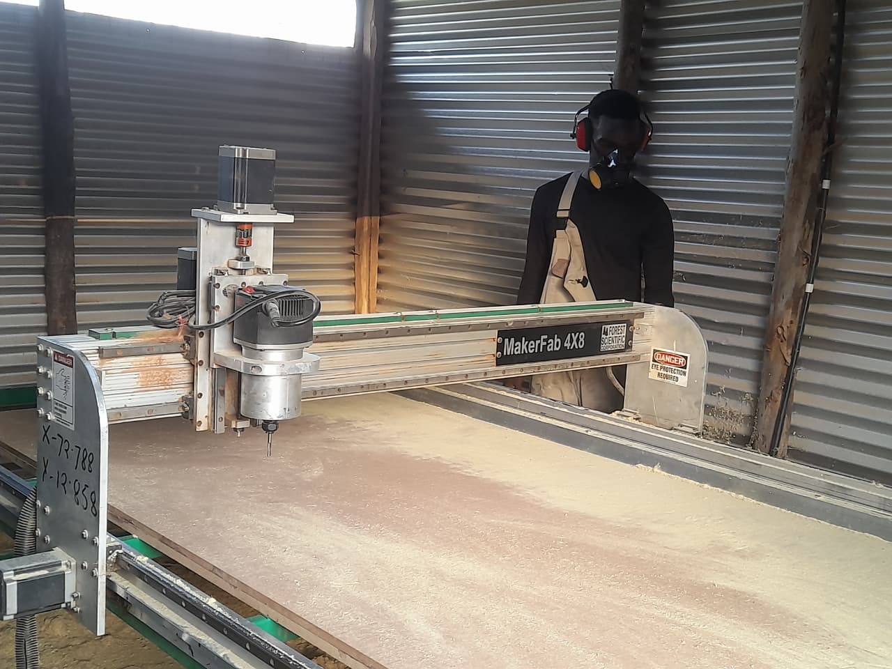
Machine Specifications
| Specification | Details |
|---|---|
| Machine Type | 3-Axis CNC Router |
| Model | MakerFab 4 × 8 CNC Router |
| Working Area | 2438 mm × 1219 mm (4 ft × 8 ft) |
| Control Software | Velocity CNC Control |
| Toolpath Software | Velocity CNC |
| Tool Used | 1/4 inch (6.35 mm) Astrolite Coated End Mill |
| Maximum Spindle Speed | Up to 24,000 RPM |
| Collet Type | ER20/ER25 |
| Power Supply | 220V AC |
2. Safety Features and Safety Training
Before operating the CNC router, we completed machine safety training. The training focused on understanding the machine’s safety features, safe operating procedures, and the correct response to emergencies.
Safety Features
Emergency Stop
The CNC router is equipped with an emergency stop button. The emergency stop should be activated immediately in case of danger, unexpected machine movement, tool failure, or any other unsafe condition.

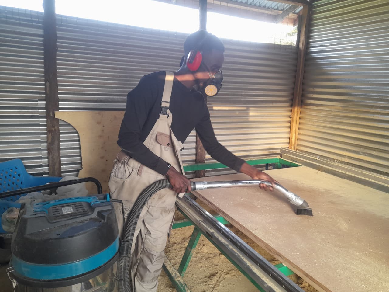
Dust Extraction
Dust should be removed from the machine bed and surrounding area using a vacuum cleaner. This helps maintain a clean working environment and reduces the accumulation of dust during machining.
Safety Training Covered
The training covered:
- Emergency stop procedures.
- Proper use of eye protection.
- Use of hearing protection during machining.
- Use of dust masks when working with dusty materials.
- Safe tool changing procedures.
- Proper methods of securing workpieces.
- Safe machine startup and shutdown.
- Keeping the machine bed and surrounding workspace clean.
- Ensuring that the toolpath is safe before starting the machine.
Surfacing
Surfacing is the process of using a wide, flat router bit to shave a thin layer off a material, creating a perfectly flat and level surface.
Types of Surfacing
-
Spoilboard Surfacing: Shaving down the sacrificial MDF or wood wasteboard attached to your CNC bed. This makes the board parallel to the router’s path so your cut depths stay accurate.
-
Workpiece Flattening: Leveling raw materials like warped live-edge wood slabs, glue-ups, or epoxy pours before final carving
Spoilboard Surfacing
We performed spoilboard surfacing to create a more uniform working surface and reduce variations in the cutting load during CNC machining. An uneven spoilboard can cause the cutting tool to engage the material at different depths across the work area, resulting in variations in cutting force and machine load.
To characterize the spoilboard, we marked several measurement points across its surface and measured the Z-axis distance at each point.
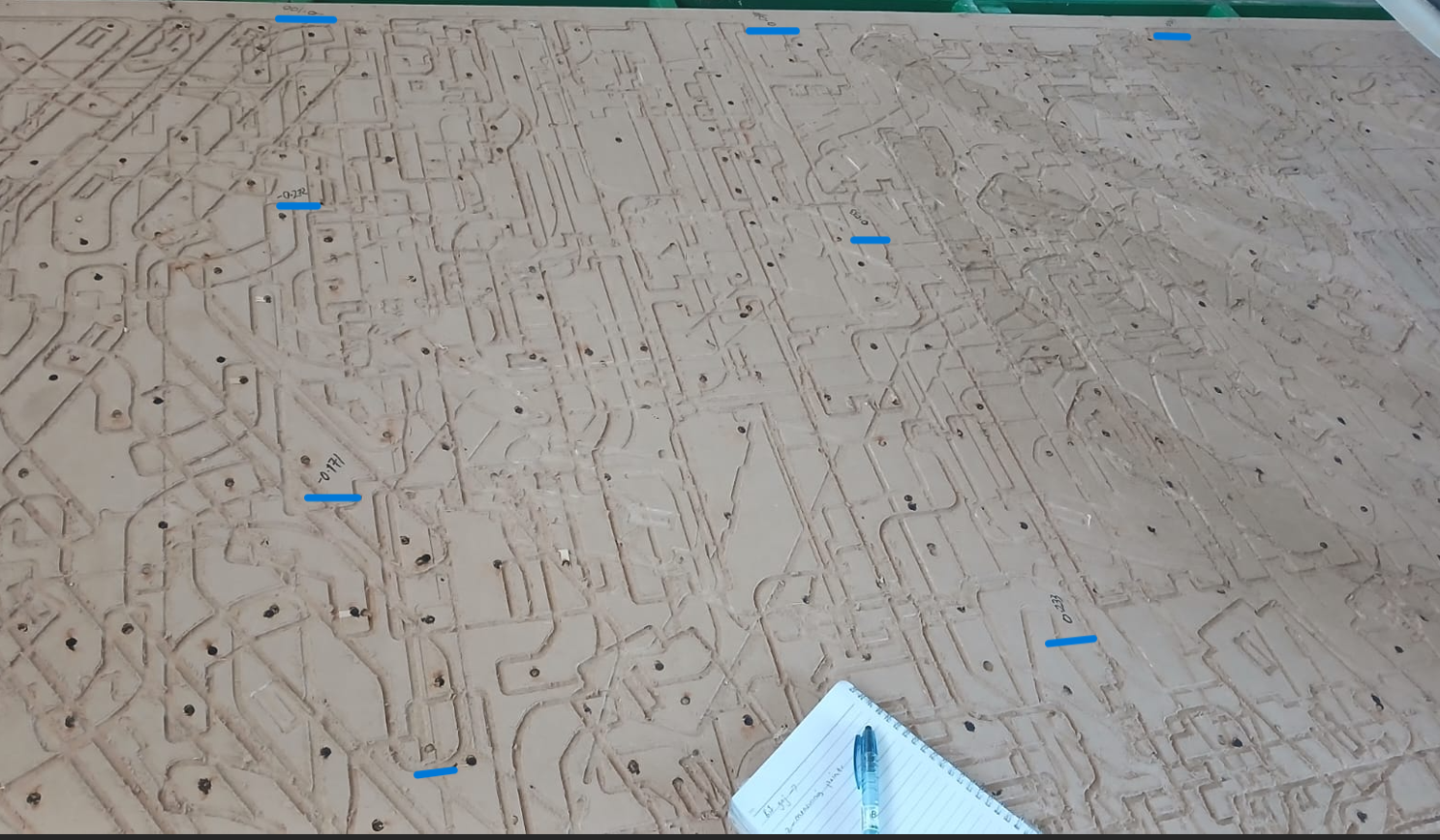

The measurements allowed us to identify the maximum and minimum Z positions and determine the difference in height between them. This difference represented the unevenness of the spoilboard.
The highest point was +0.329 mm, while the lowest was −0.448 mm, giving a total variation of 0.777 mm.

We used the highest point as our Z reference instead of zeroing with the 0.777 mm difference. This ensured consistent tool engagement and chip load during surfacing, producing a more uniform spoilboard.
After determining the variation, we could calculate the required surfacing depth. However, rather than using only the calculated difference as the reference, we used the maximum measured Z distance to set the surfacing depth. This ensured that the cutter reached all the higher areas of the spoilboard and produced a more consistent surface.
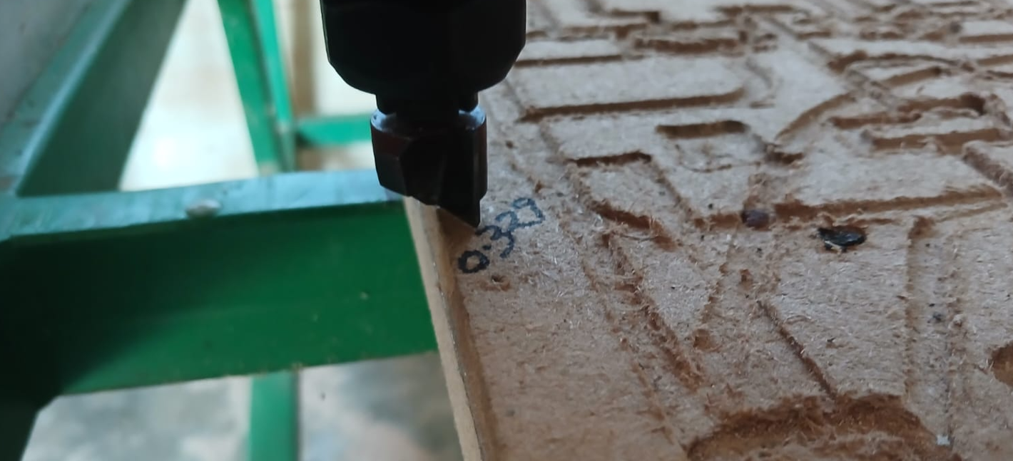
A level spoilboard helps maintain a more consistent cutting depth across the work area. This reduces sudden changes in tool engagement, which can cause variations in cutting load, tool deflection, surface quality, and machining accuracy. The surfacing process therefore helped us establish a more reliable baseline for subsequent CNC operations.
3. Design Process
To characterize the CNC machine, we created a simple test design that could be machined from plywood.
The test piece was designed as a 100 mm × 100 mm rectangle and was intended to be cut from an 18 mm plywood sheet.
Creating the Design
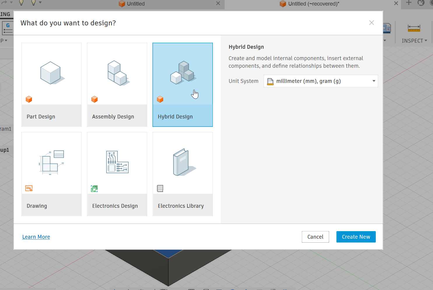
I created the design using Autodesk Fusion.
I selected the Hybrid design environment because it provides the necessary modelling features for creating the test piece.
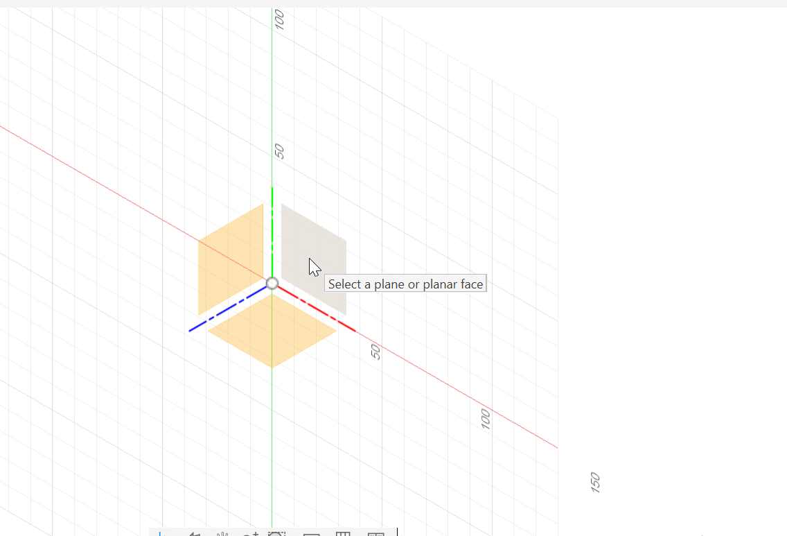
A sketch was created on the XY plane. The plane was selected according to the physical orientation of the CNC machine bed so that the X, Y, and Z axes corresponded correctly with the machine coordinates.
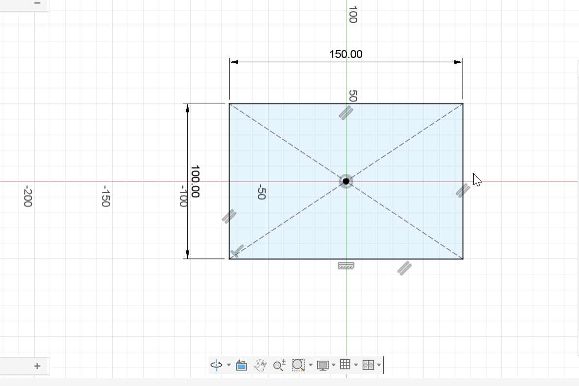
The rectangle was drawn with dimensions of:
- Length: 100 mm
- Width: 100 mm
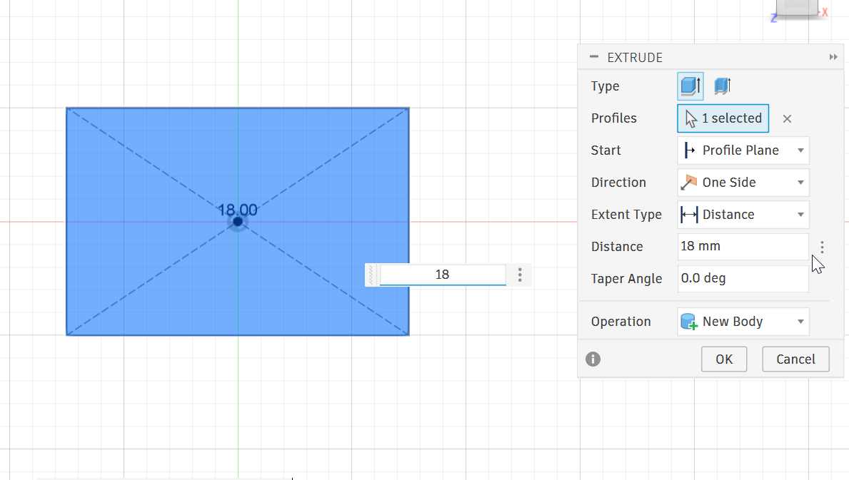
The sketch was then extruded to match the thickness of the plywood being tested.
- Material thickness: 18 mm
4. CNC Setup
After completing the CAD model, I prepared the design for machining.
Under Manufacture, I selected Milling and created a new machine setup.
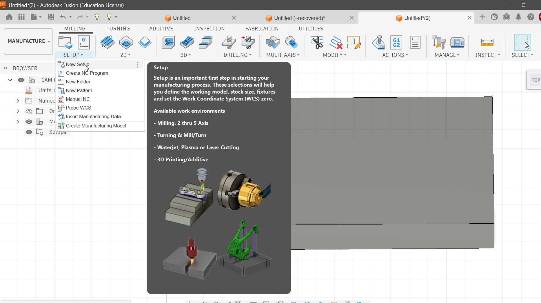
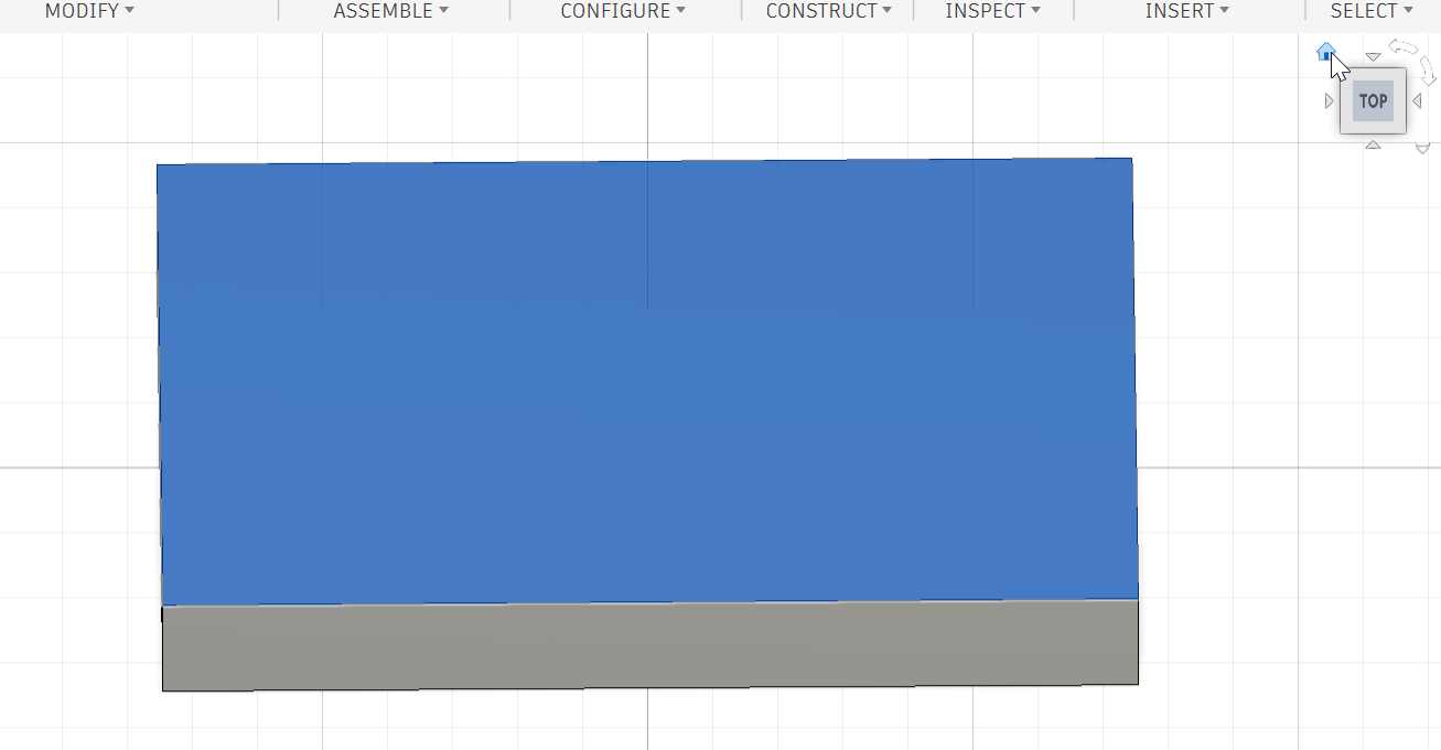
5. Stock Setup
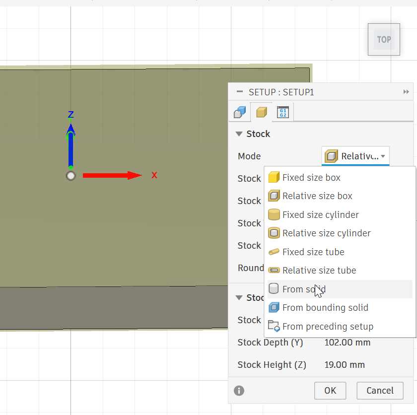
The stock was configured based on the actual material that would be machined.
I selected From Solid because I wanted the stock to correspond to the complete solid body created in the CAD design.
The designed body was then selected as the stock geometry.
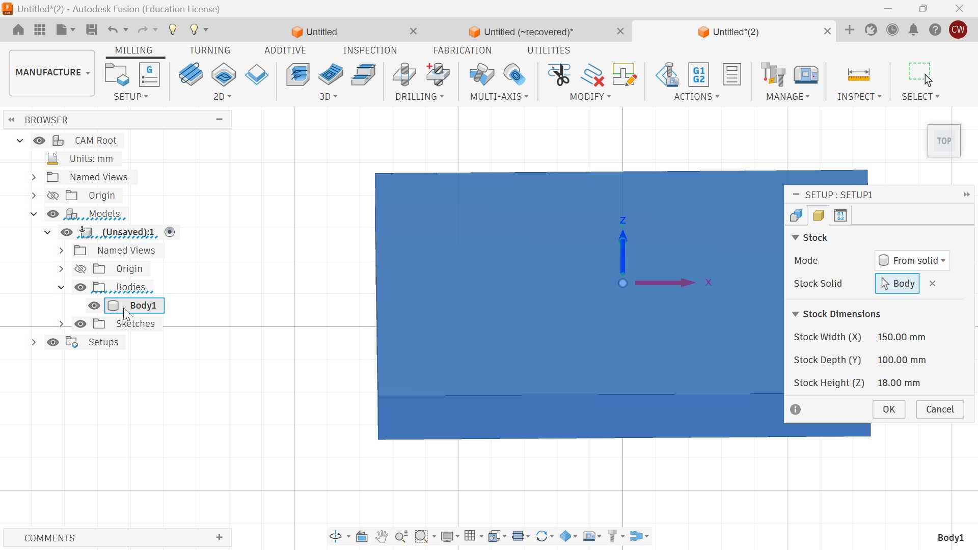
This ensured that the CAM environment represented the material and geometry correctly before generating the toolpath.
6. Toolpath Generation
After creating the machine setup and defining the stock, I generated the toolpath for machining the test piece.
The toolpath generation process involved:
- Selecting the machining operation.
- Selecting the cutting tool.
- Defining spindle speed and feed rate.
- Selecting the geometry to be machined.
- Defining the cutting depths.
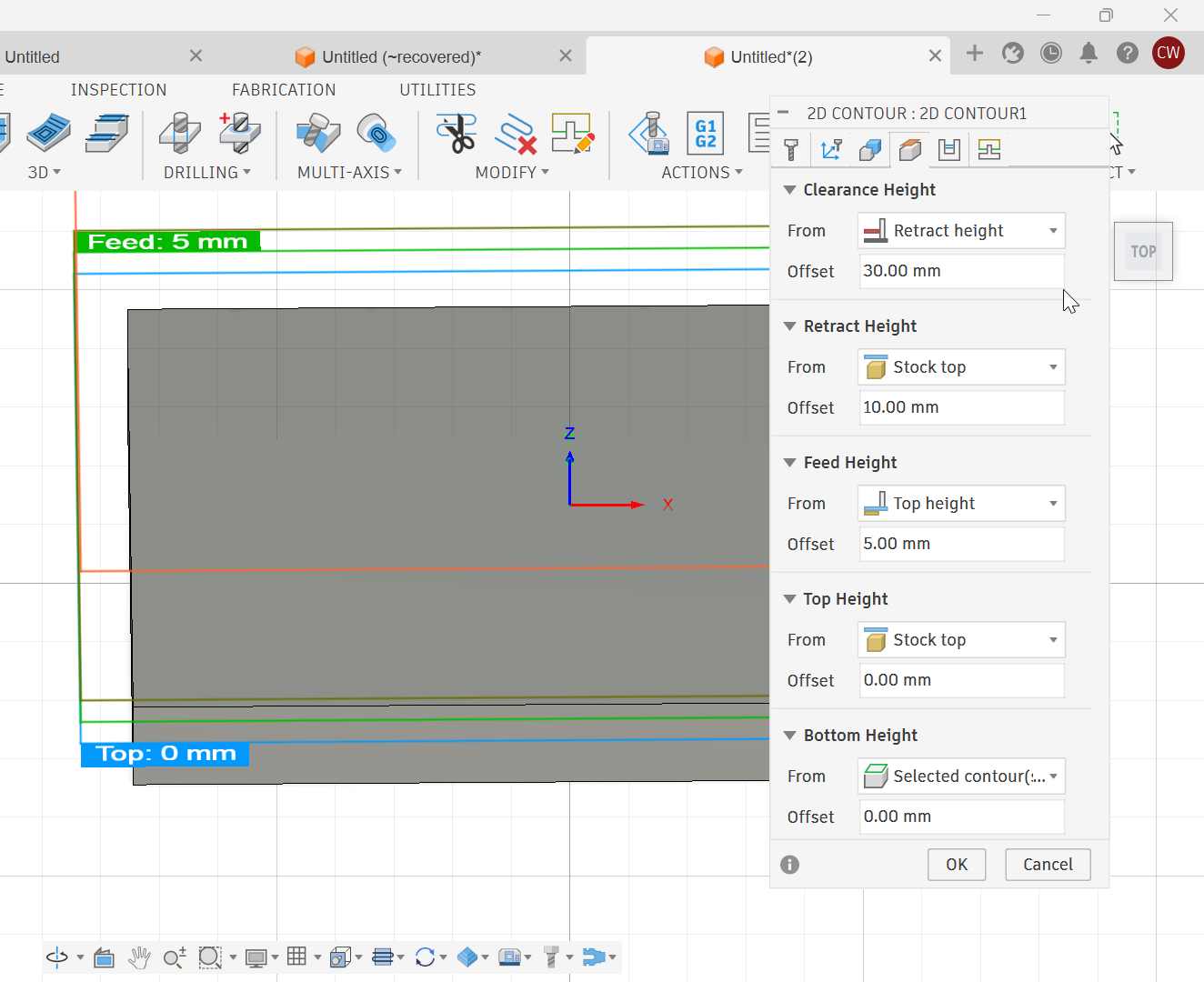
- Setting clearance and retract heights.
- Simulating the toolpath before machining.
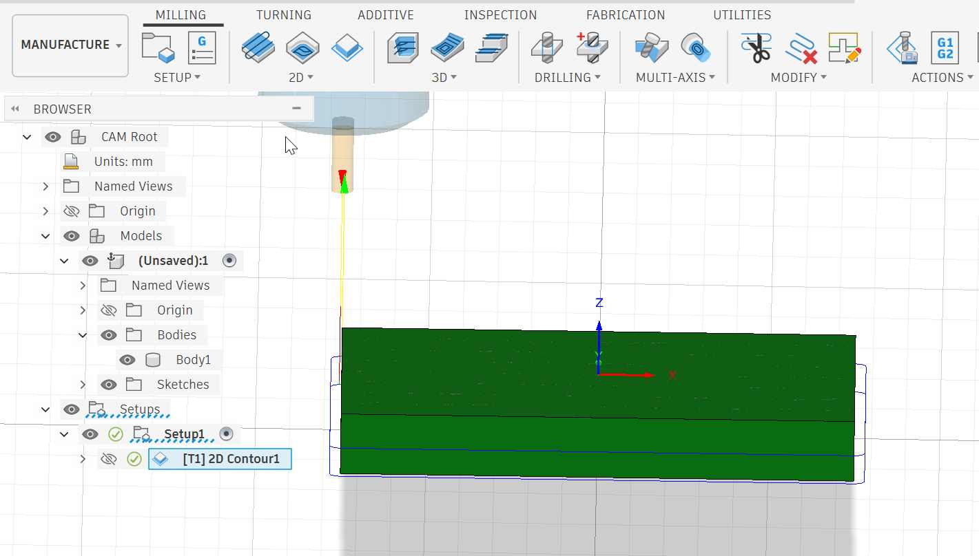
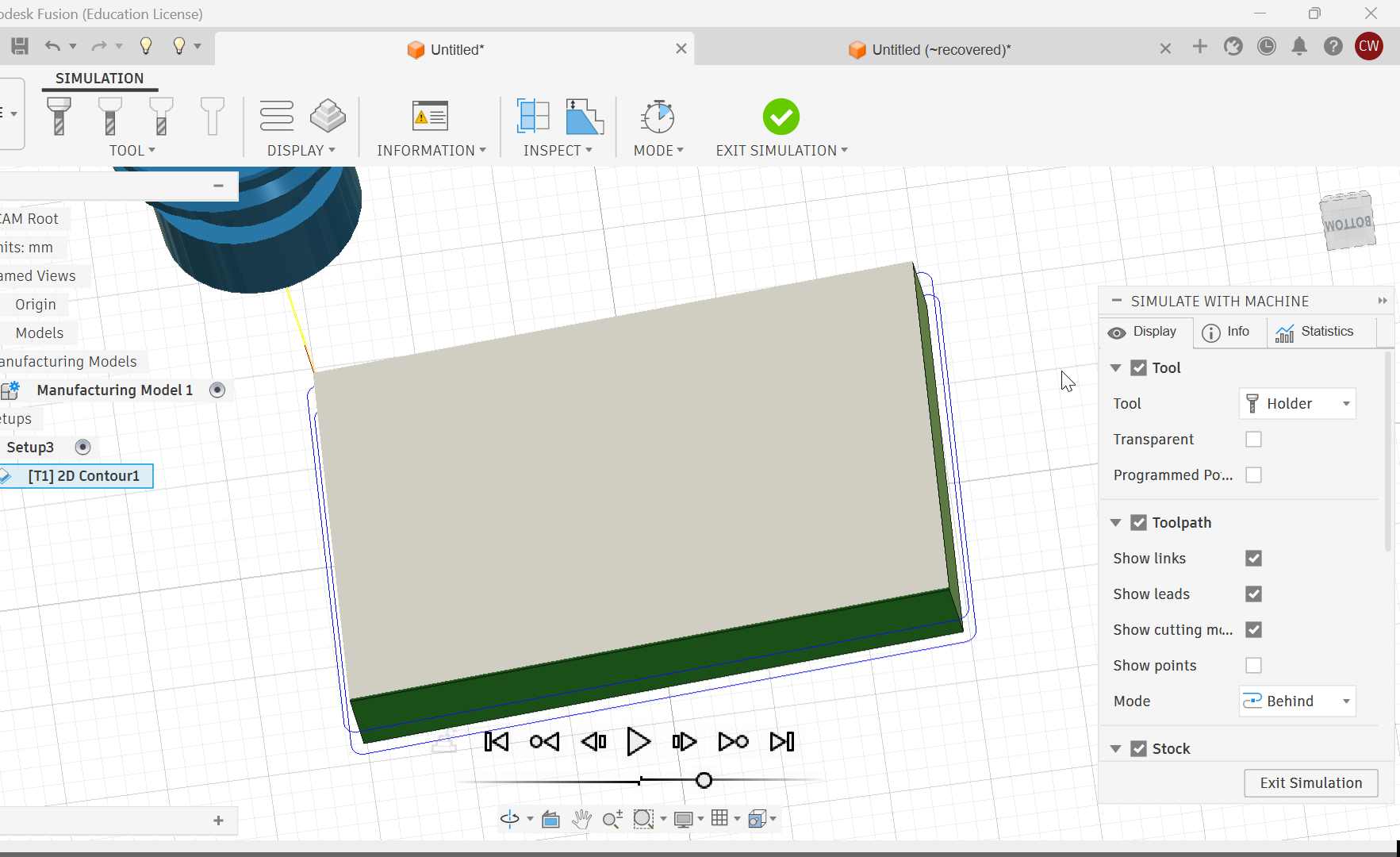
The toolpath was simulated to check for possible collisions and confirm that the cutter followed the intended geometry.
7. 2D Contour Toolpath
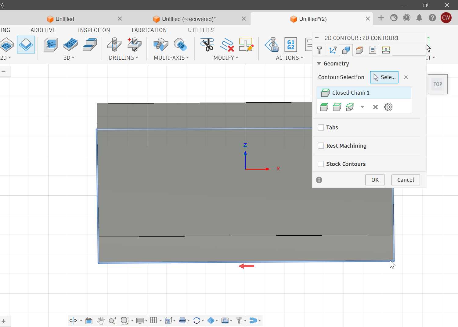
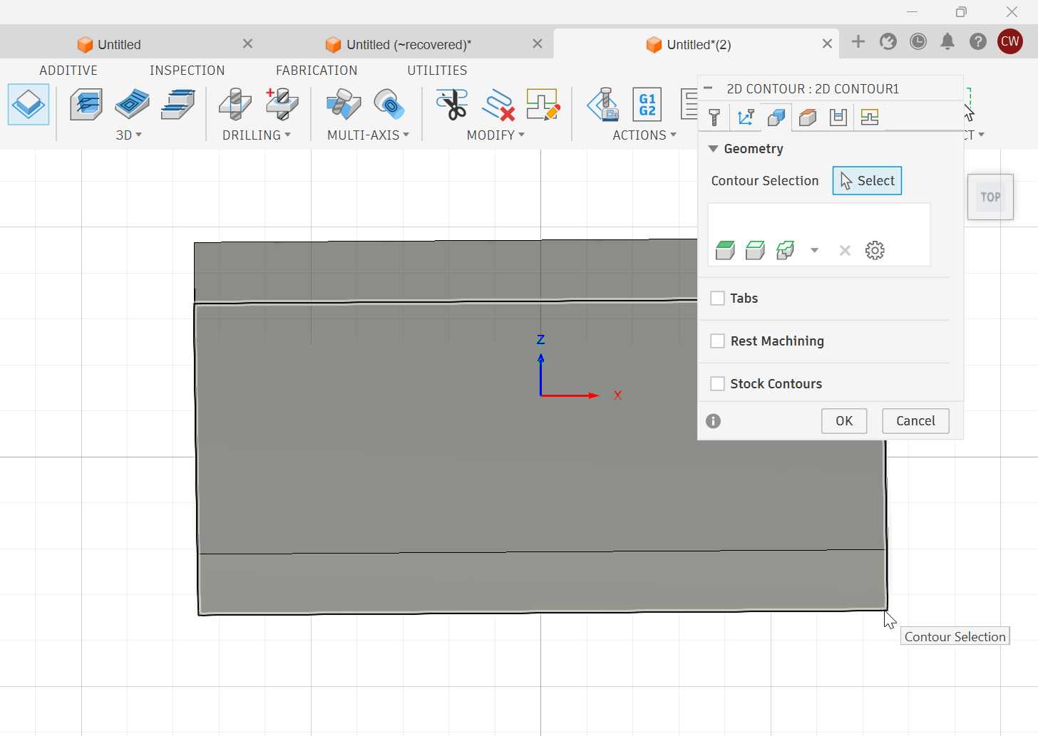
A 2D Contour operation was used to cut the external geometry and create the required through-cut.
A 2D contour toolpath was appropriate because the objective was to cut around the boundary of the designed part.
Tool Selection
A 1/4 inch (6.35 mm) flat end mill was selected for the operation.
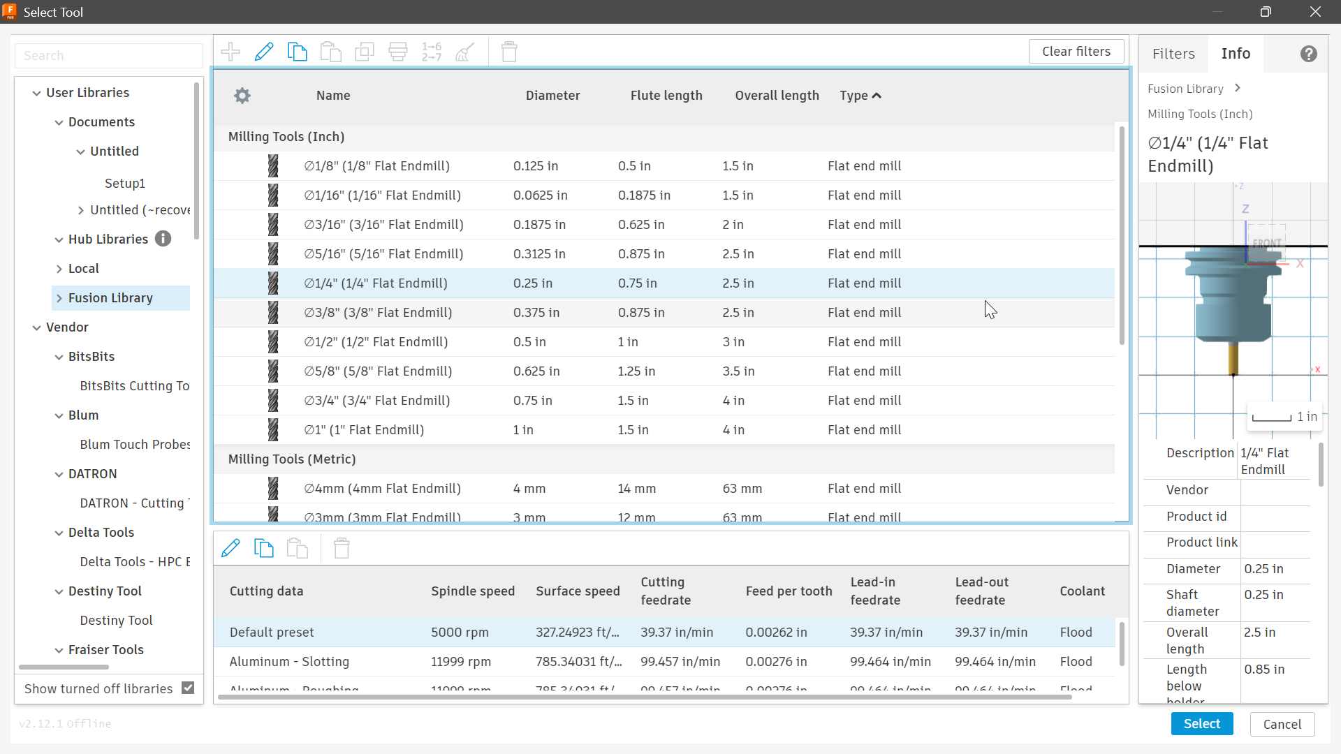
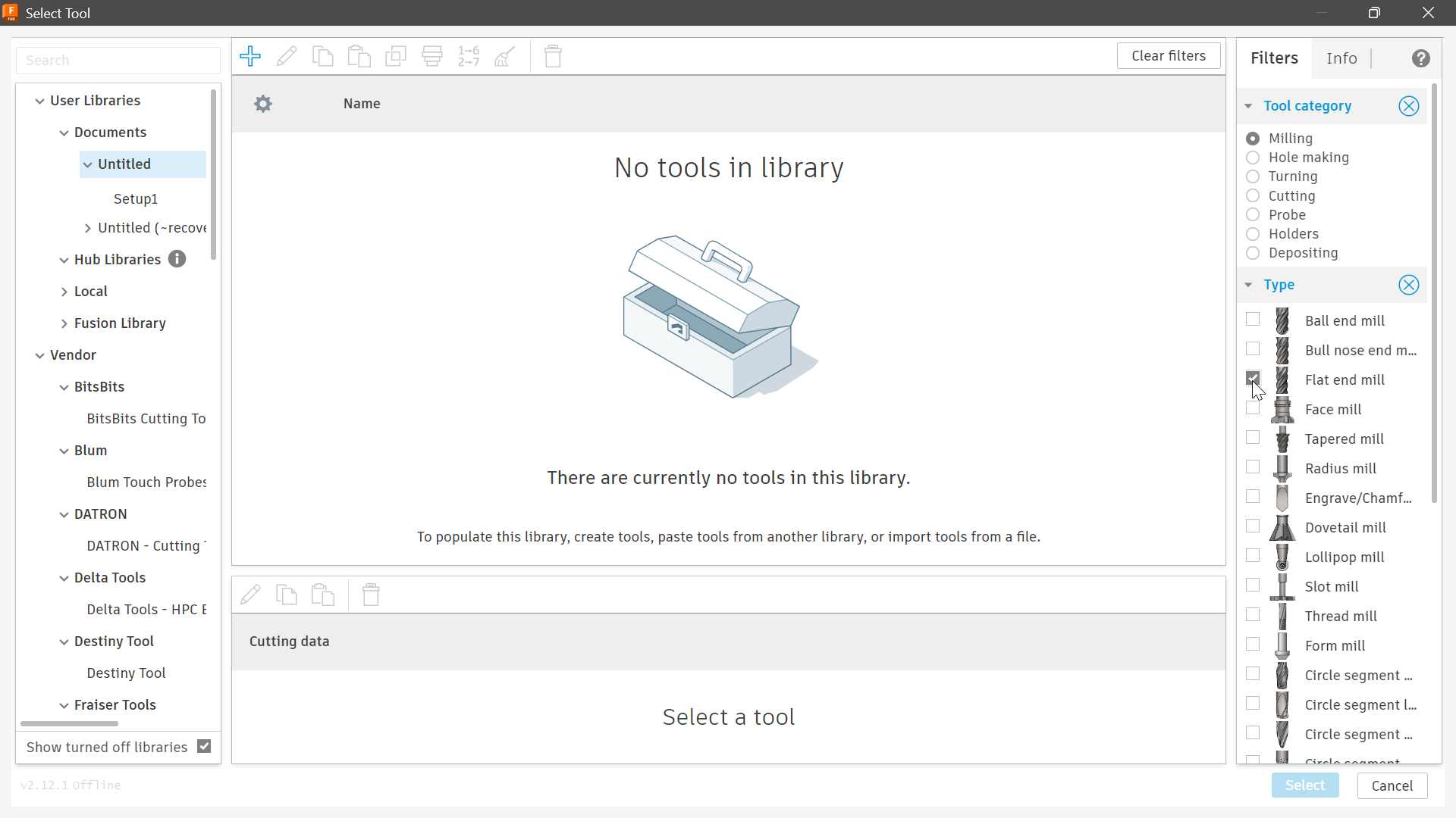
The tool was selected because it is suitable for cutting plywood and provides a relatively good balance between cutting speed, rigidity, and surface finish.
8. Spindle Speed and Cutting Parameters
The spindle speed and other cutting parameters were configured according to the selected tool and plywood material.
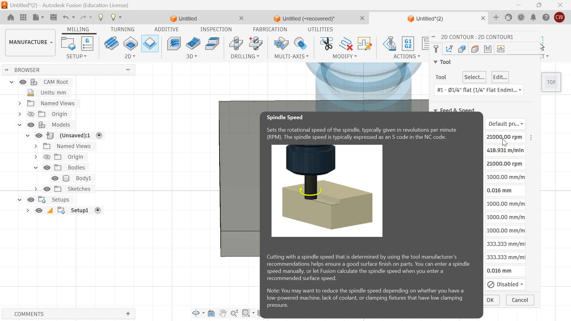
The final speeds and feeds used during the test were:
| Parameter | Value |
|---|---|
| Tool Diameter | 6 mm |
| Spindle Speed | 21,000 RPM |
| Feed Rate | 3,000 mm/min |
| Plunge Rate | 1,000 mm/min |
| Depth per Pass | 3 mm |
Multiple passes were used rather than attempting to cut the complete 18 mm thickness in a single pass.
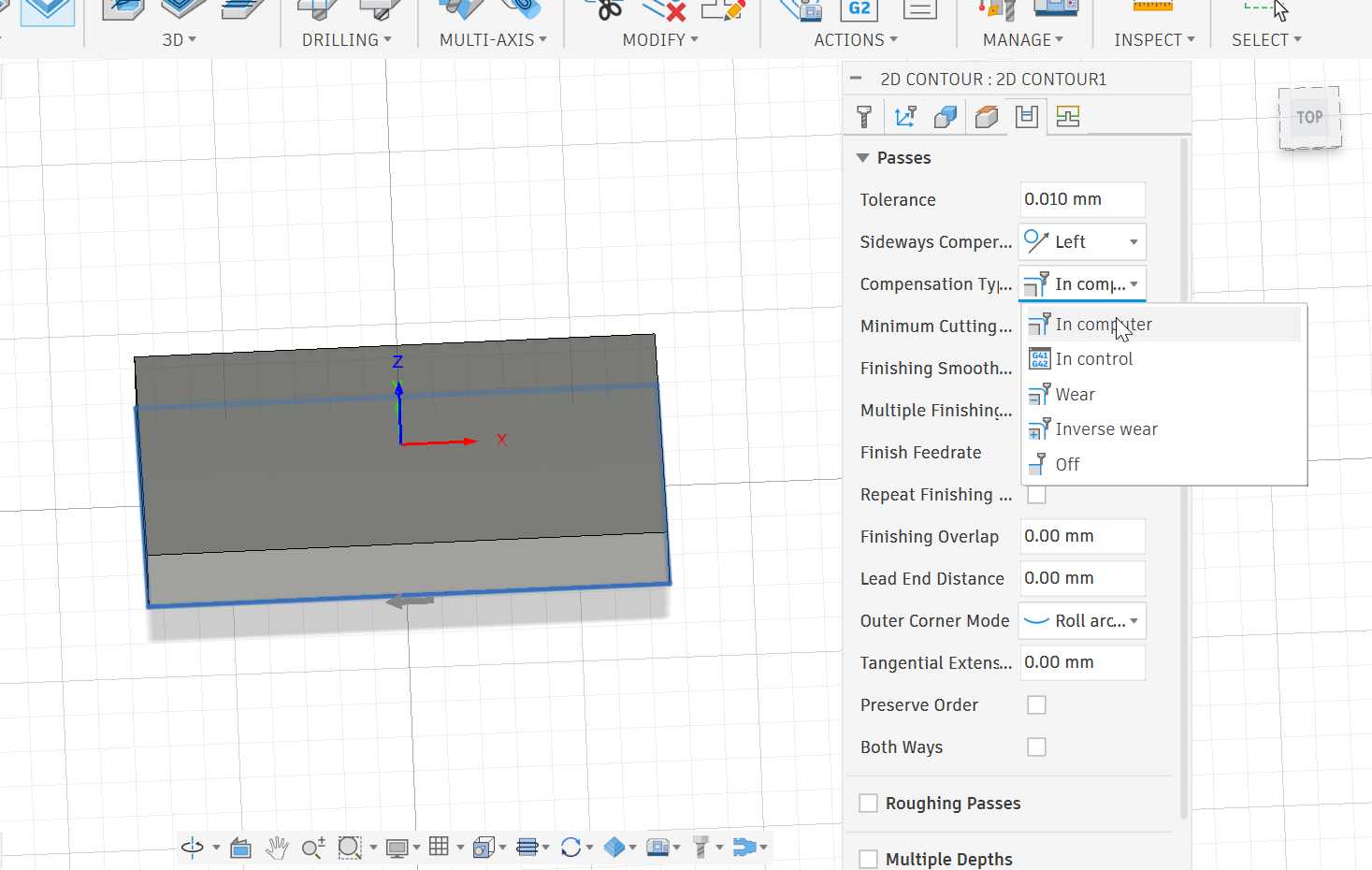
The clearance height was also configured to provide sufficient distance between the tool and the material when the tool was moving between machining operations.
9. Runout Test
Runout was evaluated by installing a 6 mm end mill in the spindle and manually rotating the spindle while observing the movement of the tool.
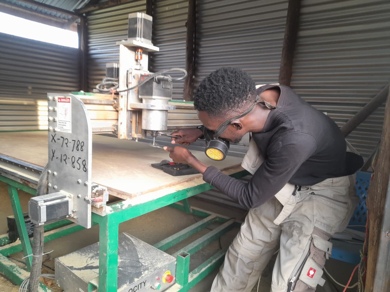
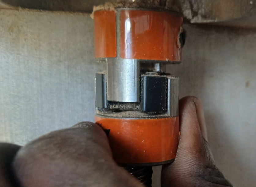
The test was used to check whether the tool showed excessive wobbling or lateral movement.
Observation
The tool showed minimal visible wobble during the manual rotation test. This indicated that the spindle and tool mounting were sufficiently aligned for the type of woodworking operations being performed.
The machine also showed no obvious signs of excessive backlash during the physical inspection.
Result
No significant spindle runout or mechanical movement was observed that would negatively affect the machining process.
10. Alignment Test
Machine alignment was evaluated by comparing the dimensions of machined features with their original CAD dimensions.
The following measurements were obtained:
| Feature | Designed Dimension | Measured Dimension | Difference |
|---|---|---|---|
| Slot Width | 18 mm | 18.2 mm | +0.2 mm |
| Tab Width | 18 mm | 17.9 mm | -0.1 mm |
| Panel Length | 500 mm | 499.8 mm | -0.2 mm |
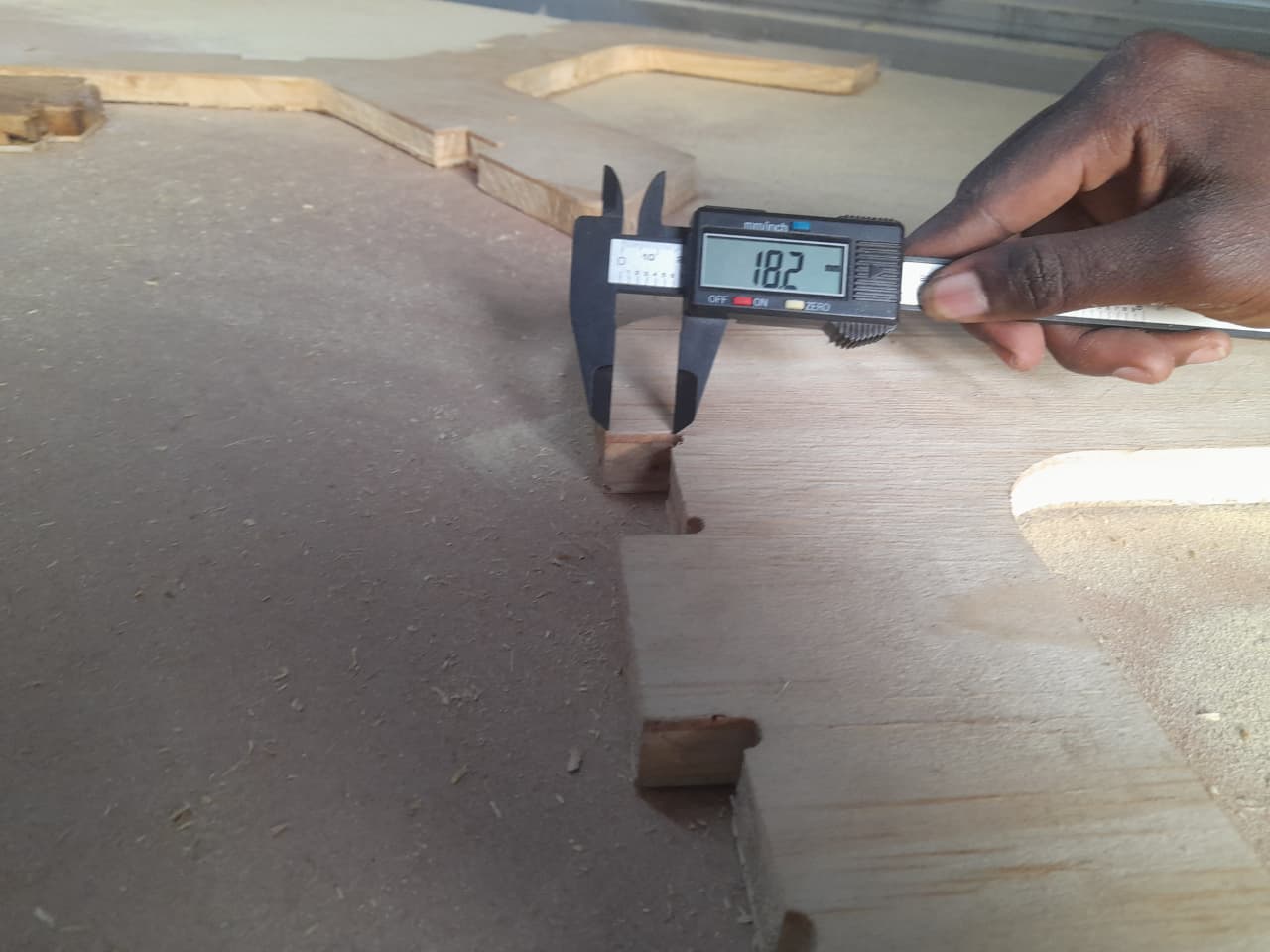
The measured dimensions were close to the original CAD dimensions, indicating that the CNC machine was capable of producing parts with acceptable dimensional accuracy.
11. Fixturing Test
The workpiece was secured to the CNC machine bed using wood screws attached to the spoilboard.
This method provided a strong mechanical connection between the workpiece and the machine bed.
Advantages
- Strong workholding.
- Prevented material movement during machining.
- Suitable for large sheet materials.
- Simple and inexpensive to implement.
Disadvantages
- Leaves holes in the waste material.
- Screws must be positioned carefully.
- Incorrect screw placement can result in toolpath collisions.
- Requires careful planning of the cutting area.
The workholding method proved reliable during the machining test, with no significant movement of the workpiece.
12. Speeds and Feeds Evaluation
The CNC machine was tested while machining 18 mm plywood using a 6 mm flat end mill.
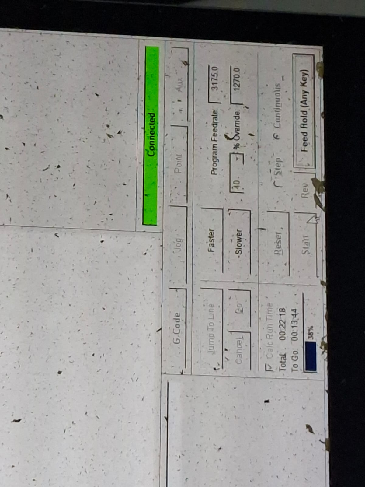
The following parameters were used:
| Parameter | Value |
|---|---|
| Material | 18 mm Plywood |
| Tool Diameter | 6 mm |
| Spindle Speed | 18,000 RPM |
| Feed Rate | 3,000 mm/min |
| Plunge Rate | 1,000 mm/min |
| Depth per Pass | 3 mm |
Observations
During machining:
- Cutting action was smooth.
- There was no excessive vibration.
- Minimal burning was observed.
- The resulting edges had a good finish.
- The machine maintained the workpiece securely during cutting.
These results indicated that the selected speeds and feeds were suitable for the tested plywood and 6 mm end mill.
13. Material Evaluation
The main material tested during the characterization was:
18 mm Plywood
Observations
The plywood was found to be:
- Easy to machine.
- Structurally strong.
- Suitable for CNC cutting.
- Suitable for press-fit assemblies.
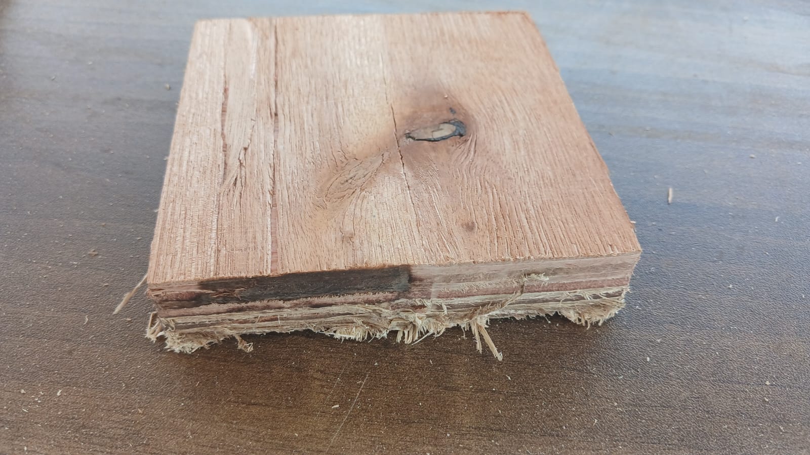
- Subject to minor edge tear-out in some areas.
Overall, the material performed well with the selected cutting parameters.
14. Toolpath Evaluation
Different toolpaths were considered according to the machining operation required.
Profile / Contour Toolpath
The profile toolpath was used to cut the external geometry of the part.
Advantages
- Produces accurate external dimensions.
- Suitable for through-cuts.
- Provides an efficient cutting process.
Pocket Toolpath
The pocket toolpath is used to remove material from internal regions of a part.
Advantages
- Suitable for creating internal features.
- Provides consistent material removal.
- Allows controlled cutting depths.
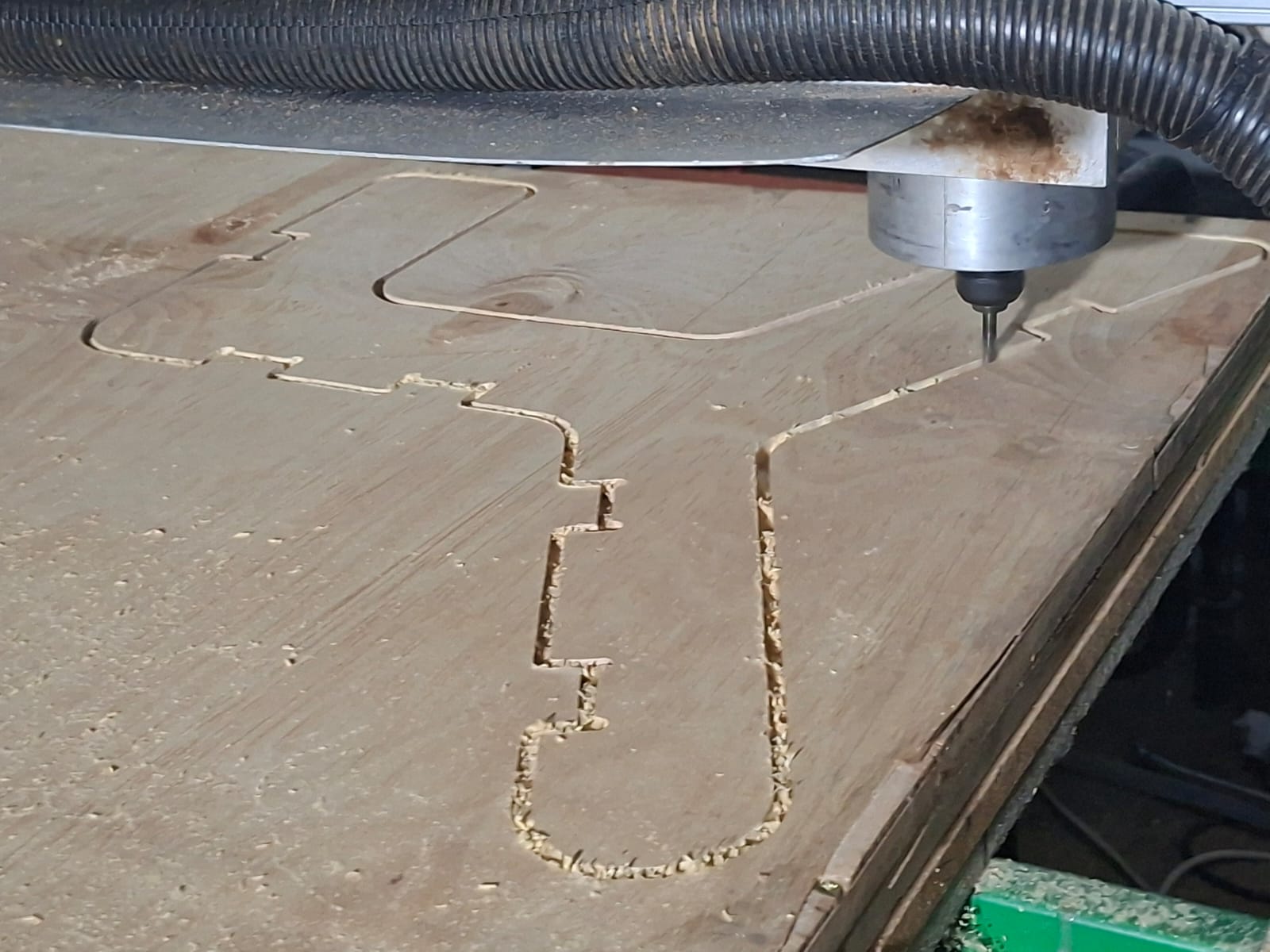
Dogbone Features
Dogbone features were used to compensate for the circular geometry of the CNC cutter when creating press-fit joints.
Because a round cutter cannot produce perfectly square internal corners, dogbone reliefs provide additional clearance at the corners.
Advantages
- Improved press-fit assembly.
- Better fit between mating parts.
- Reduced need for manual post-processing.
15. Toolpath Simulation
Before machining, the generated toolpath was simulated to verify the machining process.
The simulation was used to check:
- Tool movement.
- Cutting depth.
- Contour selection.
- Multiple cutting passes.
- Clearance heights.
- Possible collisions.
- Final expected geometry.
Simulation helped identify potential problems before running the physical machine.
16. Overall Characterization Results
The CNC characterization produced the following results:
| Test | Result |
|---|---|
| Safety | Safety procedures successfully reviewed |
| Runout | Minimal visible runout |
| Backlash | No significant backlash observed |
| Alignment | Dimensions within acceptable tolerance |
| Fixturing | Screw fixturing was stable |
| Material | 18 mm plywood machined successfully |
| Speeds and Feeds | 18,000 RPM / 3,000 mm/min produced good results |
| Toolpath | Profile, pocket and dogbone operations were evaluated |
| Surface Finish | Good, with minor edge tear-out |
| Dimensional Accuracy | Close to CAD dimensions |
17. Group Learning Outcomes
Through this assignment, the group:
- Learned CNC machine safety procedures.
- Learned how to safely operate and prepare the CNC router.
- Learned how to check spindle runout and machine alignment.
- Learned different methods of securing material to the CNC bed.
- Learned the relationship between feed rate, spindle speed, cutting depth, and cutting quality.
- Observed how tooling parameters affect machining performance.
- Learned how to generate and simulate CNC toolpaths.
- Gained experience with profile, pocket, and dogbone operations.
- Improved understanding of CNC machining tolerances.
- Gained experience in collaborative problem solving during machine setup.
- Improved understanding of the complete digital fabrication workflow from CAD design to physical machining.
18. Conclusion
The Scientific Forest CNC router at Fab Lab Winam demonstrated good performance for large-scale digital fabrication. The machine maintained acceptable dimensional accuracy and produced clean cuts in 18 mm plywood using a 6 mm flat end mill.
The runout test showed minimal visible tool wobble, while the alignment test showed that the machine was capable of producing dimensions close to the original CAD design. Screw-based fixturing provided reliable workholding, and the selected speeds and feeds produced smooth cutting with minimal burning and good edge quality.
The characterization process provided practical knowledge about the machine’s capabilities, limitations, workholding methods, materials, tooling, and cutting parameters. The knowledge gained from this group assignment can be applied to future CNC machining and individual fabrication projects.