Contents
1. Obejctive
2. Output: Light -Emitting Diodes (LEDs)
3. Input: How do we connect a switch Arduino IDE
4.Microcontroller
5. Add a library on Eagle
6. Designing the Schmatic of hello board
7. Designing the Board of hello board
8. Test the hello board
9. Download
1. Obejctive
In this page you will learn, the details about some electronics hardwares and a microcontroller, how to read input from a pushbutton and how to switch LED "ON" when button is pressed.
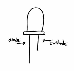
2. Output: Light -Emitting Diodes (LEDs)
Light-emitting diodes (LEDs) are the simplest type of output that can be driven by a microcontroller. From their name, they are diodes (p–n junctions in a semiconductor) that emit light. The important feature electrically is that they are diodes. This means that they pass current only in one direction. Almost no current flows if they are connected the other way around.
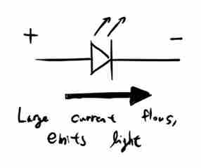
The symbol for a diode is basically an arrow: current flows in the direction of the arrow. (Remember that current flows conventionally from + to –.)
How to connect LEDs 1
Remember that LEDs are diodes, so we must connect them the correct way around! There are two ways in which this can be done.
1. Suppose that we want the LED to illuminate when the logical value of the output is high (1) — active high. Thus the LED should light when the pin is at VDD (supply, positive, logic 1) but not when the pin is at VSS (ground, negative, logic 0). We therefore connect the LED between the pin and VSS. Conventional current flows from the pin to VSS with this connection.
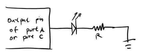
The resistor is to limit the current.
How to connect LEDs 2
It might seem obvious that you would always want to connect an LED like this but there is a second, complementary way in which this can be done.
2. Suppose that we want the LED to illuminate when the logical value of the output is low (0), active low. Thus the LED should light when the pin is at VSS (ground, negative, logic 0) but not when the pin is at VDD (supply, positive, logic 1). We therefore connect the LED between the pin and VDD. Conventional current flows from VDD to the pin with this connection.
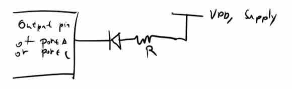
Note that the LED is the other way around and this way is less popular than the first method.
3. Input: How do we connect a switch
Suppose that we want to connect a simple on–off switch or pushbutton as an input to a μC. How should this be done? The input should be either:
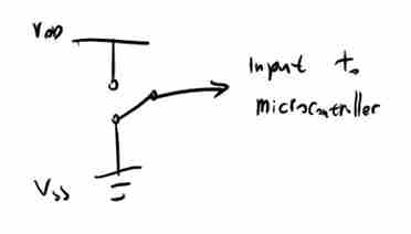
However this approach is not used because it needs an expensive switch ( 3 termintals instead of 2, it needs 2 or 3 wires and when the switch is being operated the digital circuits must never be left with their inputs "floating" / not connected. This leads to upredicatable behaviour and possibley severe problems.
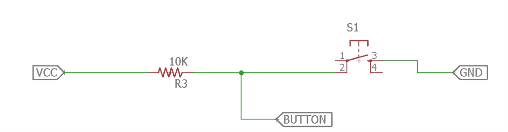
Pull Up Resistor
This is the circuit that is usually used. Traditionally the pullupresistor is around R » 10 kΩ.
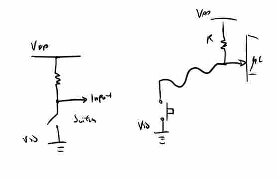
Advantages of using pullup resistor are it needs only a simple witch or push button, only one wire to the switch is usuallz needed because a fround connection can usually, be found nearby and the input is alwazs connected to something.
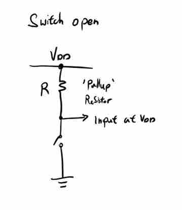
How does this work?
The input is connected to Vdd, logical1 , throught he pullup resistor when the witch is open
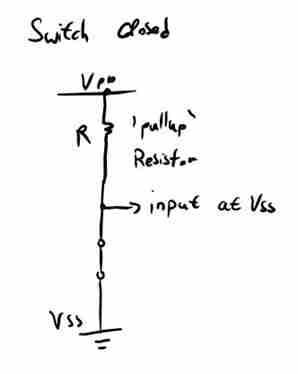
The input is connected to Vss, logical 0, through the switch when the switch is closed. A wasted current flows through the pullup resistor from Vdd to ground
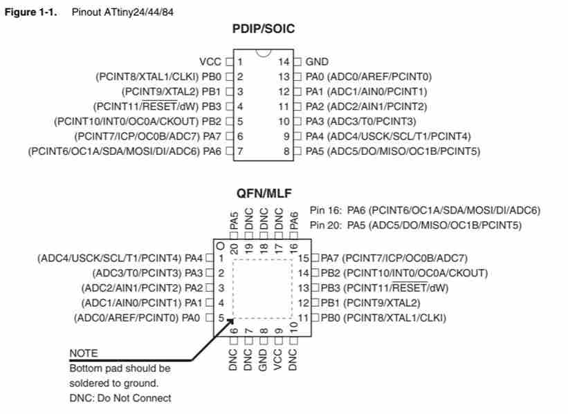
4. Microcontroller
First of all check the AT Tiny 44 pin configuration on the data sheet.
5. Add a library on Eagle
Download the FAB library,FAB library Eagle
Open Library and select Library Manager.
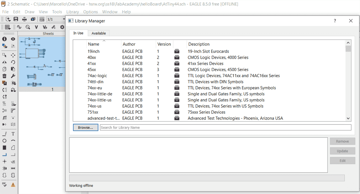
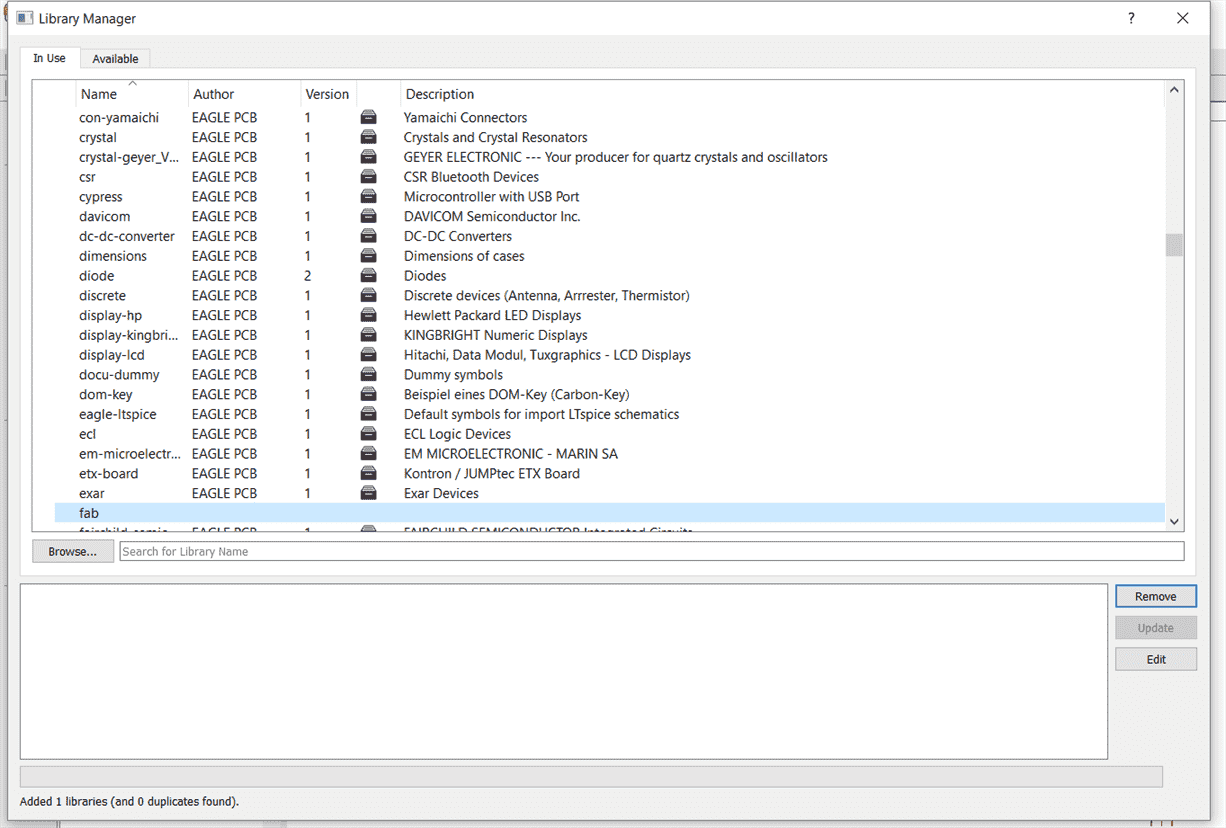
Browse the file that you have downloaded.
6. Designing the Schmatic of hello board
After you have the basics knowledge of input and output devices, let's try to design a PCB.
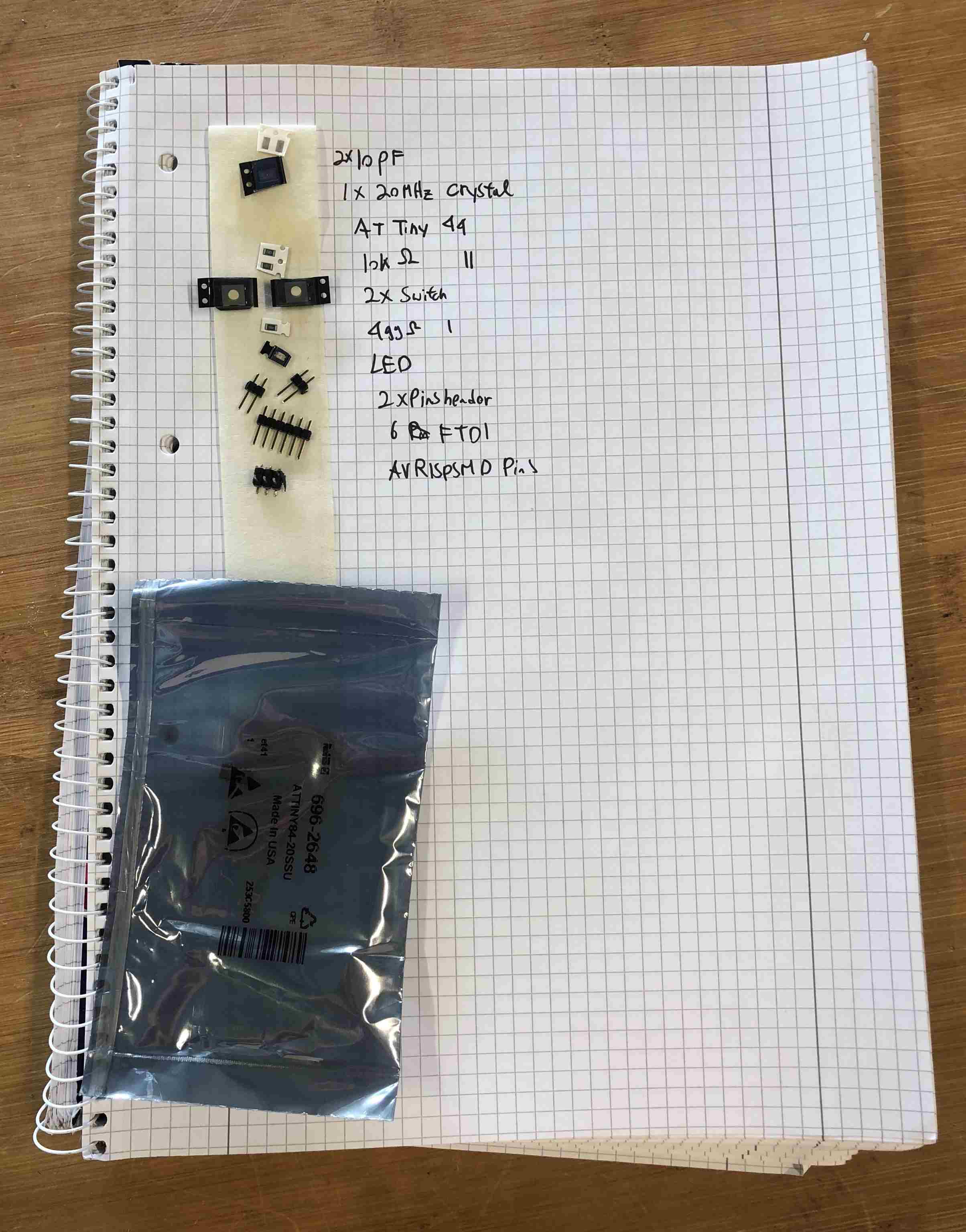
The list parts that I used for making a a hello board:
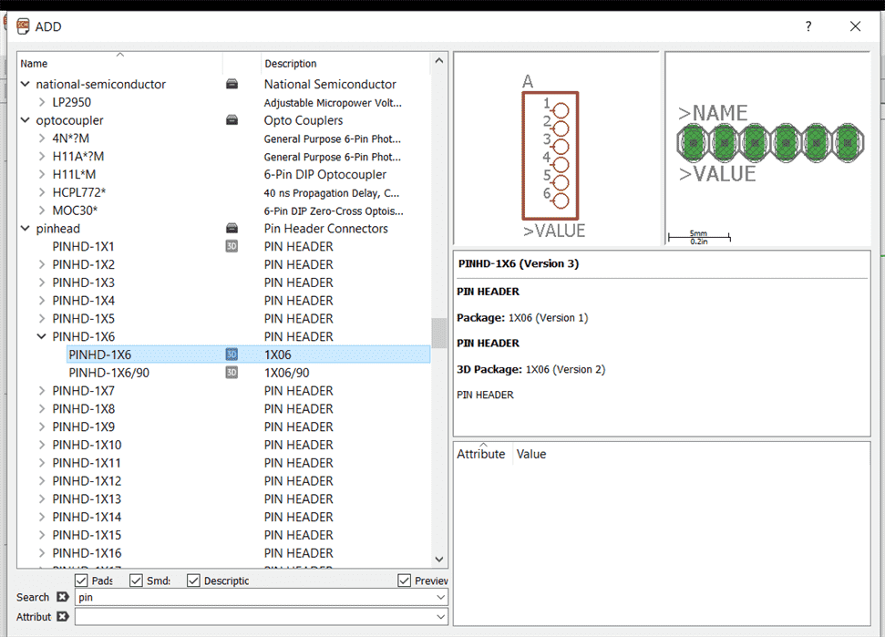
Add parts that are needed to design our hello board, we will have one input which is a button and an output which is one LED.
Select the parts that are required.
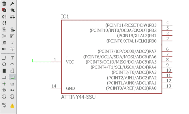
Add Tiny 48.
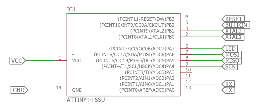
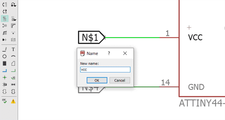
Use "NET" to wire.
Wiring up the schematic by using Net to have the connection, not wire.
I like to tag all the wires and group them according to their use.
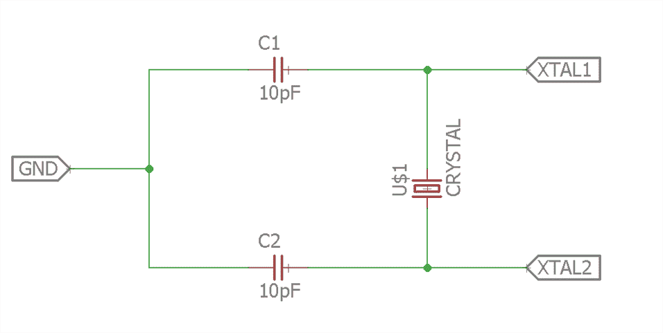
Crystal
Input Switch
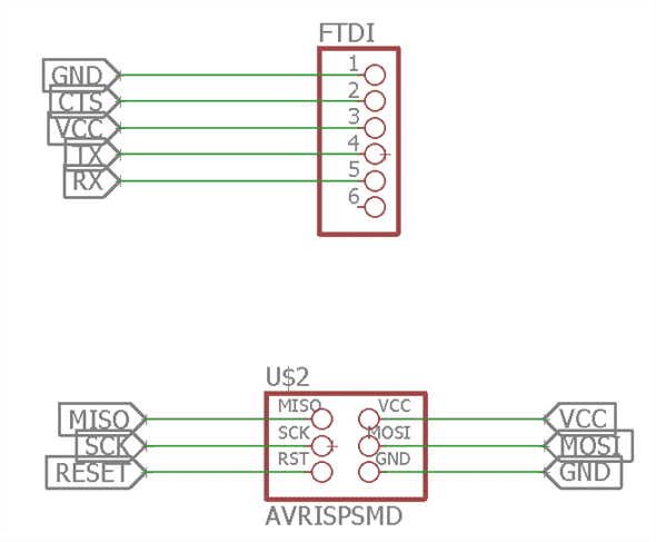
FTDI pins and AVR ISP pins
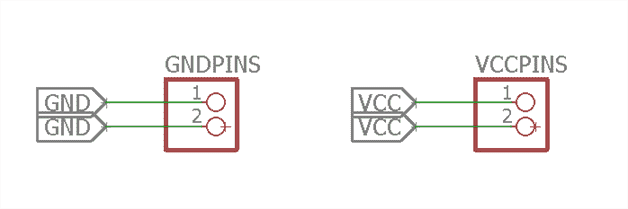
VCC and GND pins
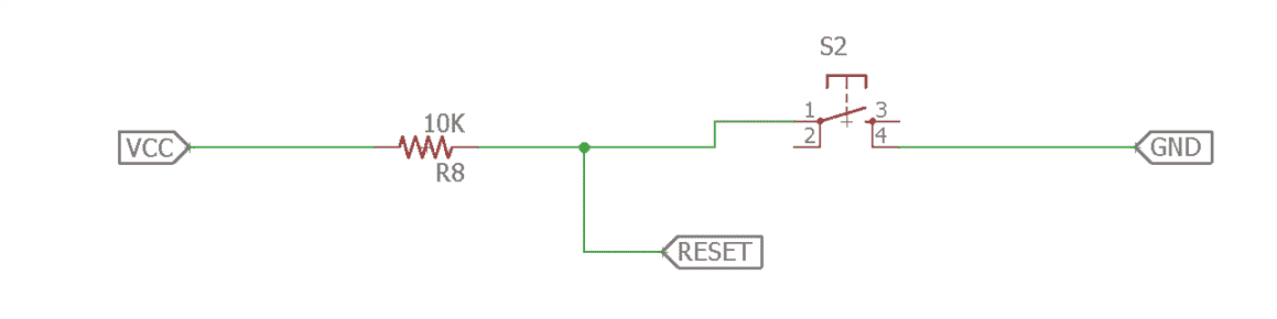
Reset
The reset should be logically high when is on and this can be found in the data sheet.
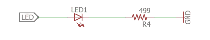
LED as the input
Add a resistor, right click on it and click value. Resistor = 499 Ohm
7. Designing the Board of hello board
File and click board, it will bring you to the board designing software.
Note that you can only click the component on the cross sign of the component.
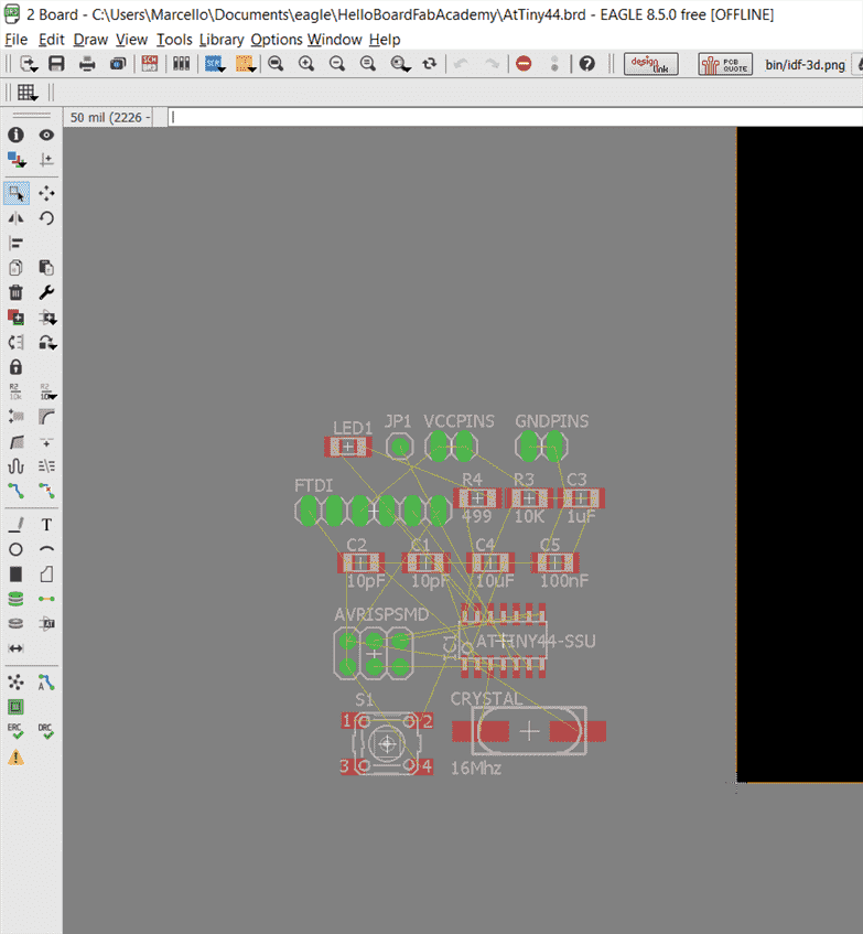
Rearrange all the parts so you can make sure that you can wire them easily.
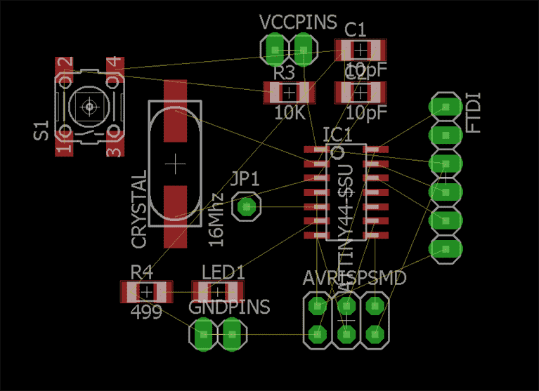
Wire them and adjust the appropiriate width
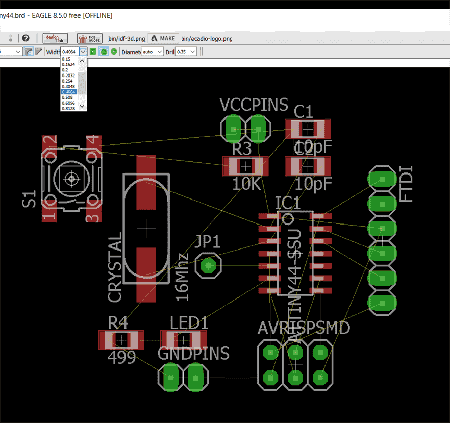
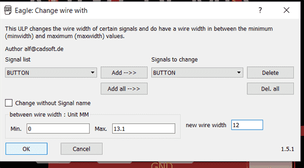
Change Wire Width
Let's say you want to change the wire thickness after you have been doing your board, we can easily change the width for all the wires.
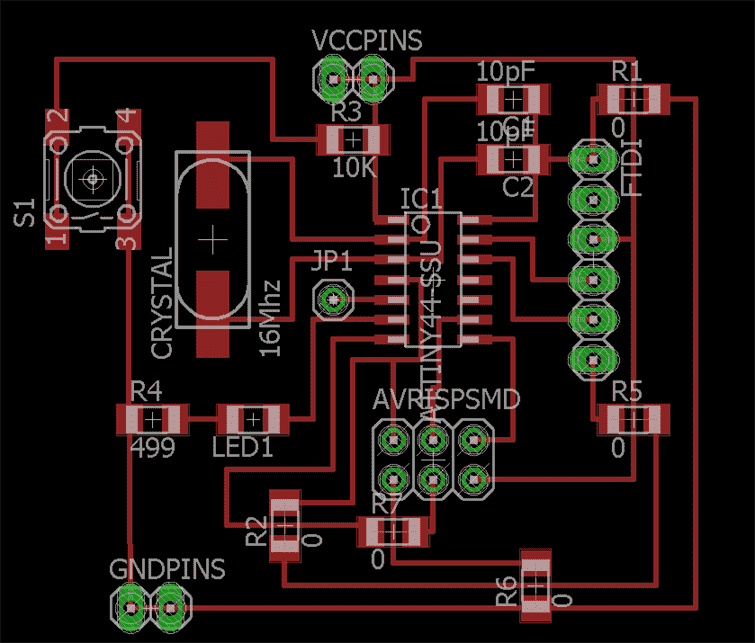
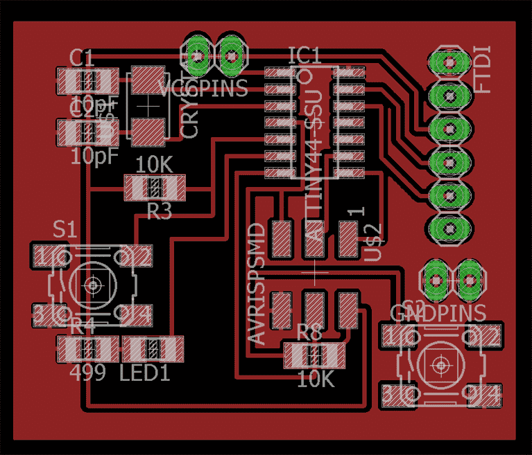
This is my first design but I have used 8 0 ohm resistor and I will have to optimize them so that can be more efficient and packed.
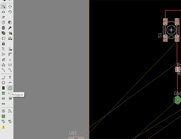
ADD ground layer
Draw a rectangle along the parts using Polygon tool.
Change the name of the rectangle into "GND"
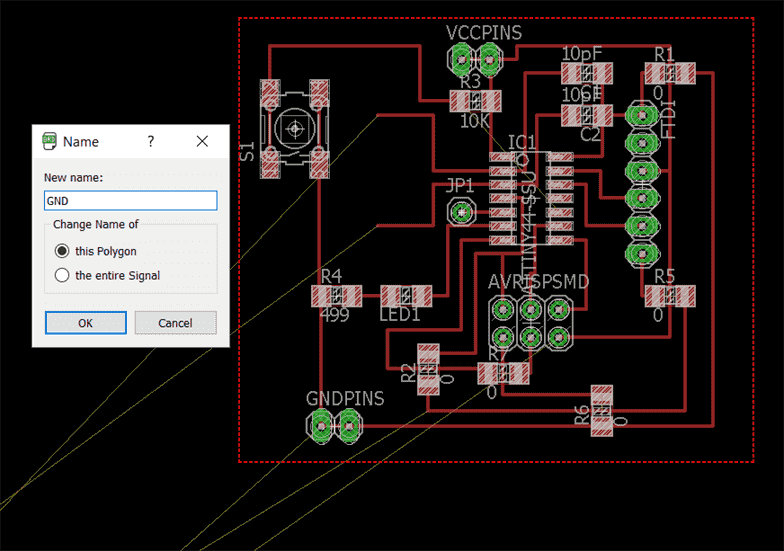
Select the suitable isolate and I choosed 0.40364.
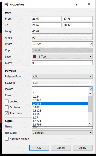
This is the result of you ground layer
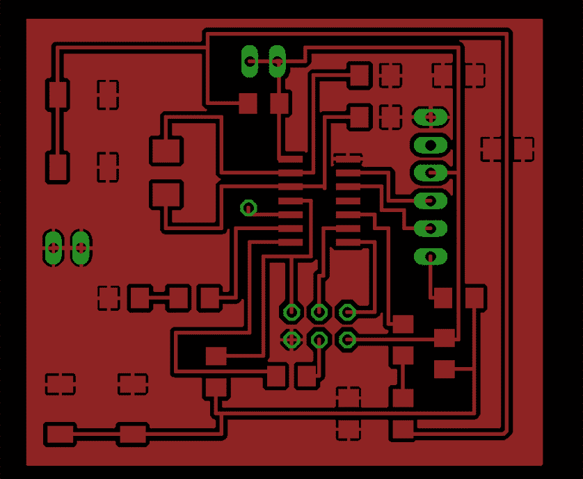
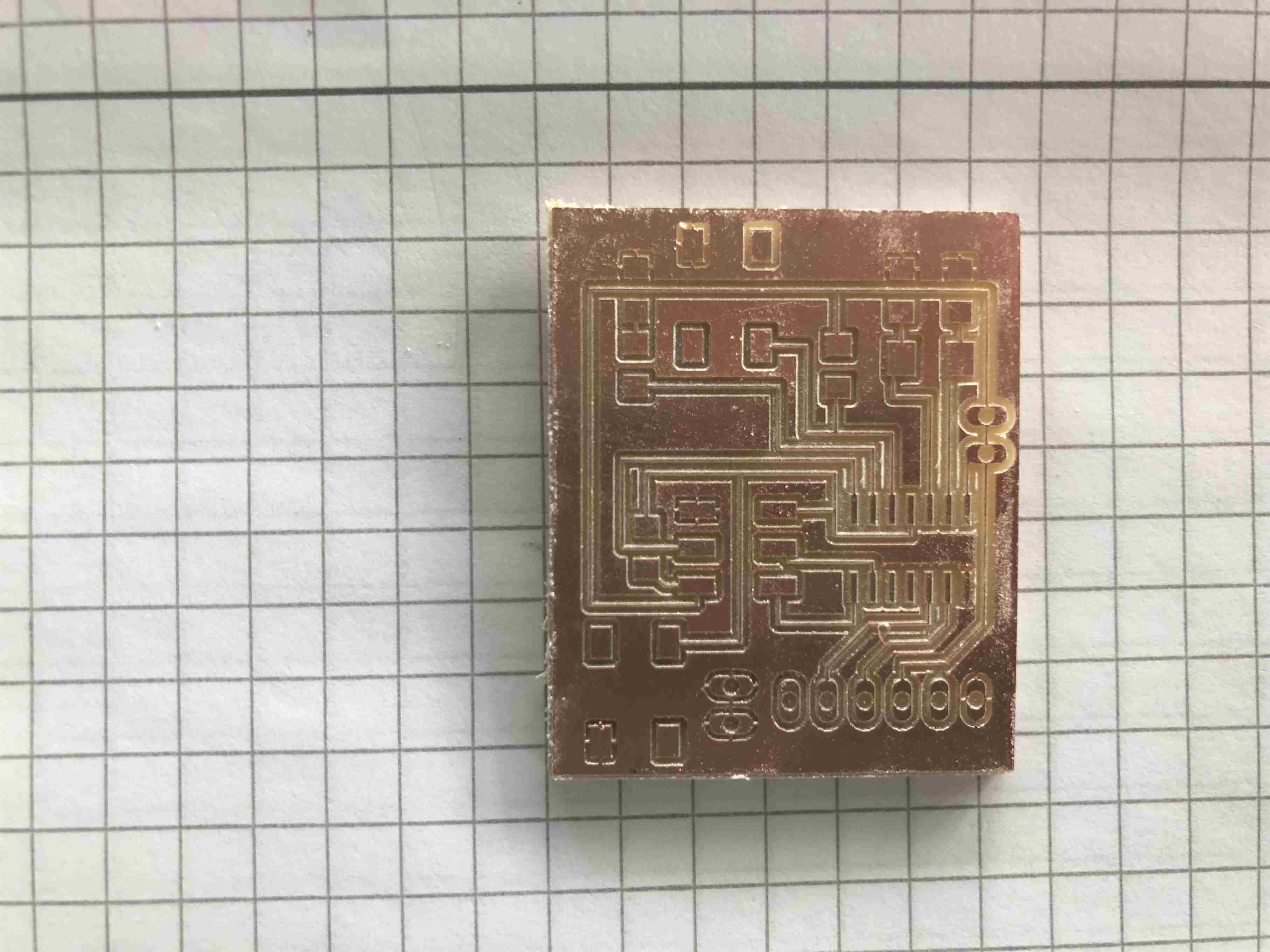
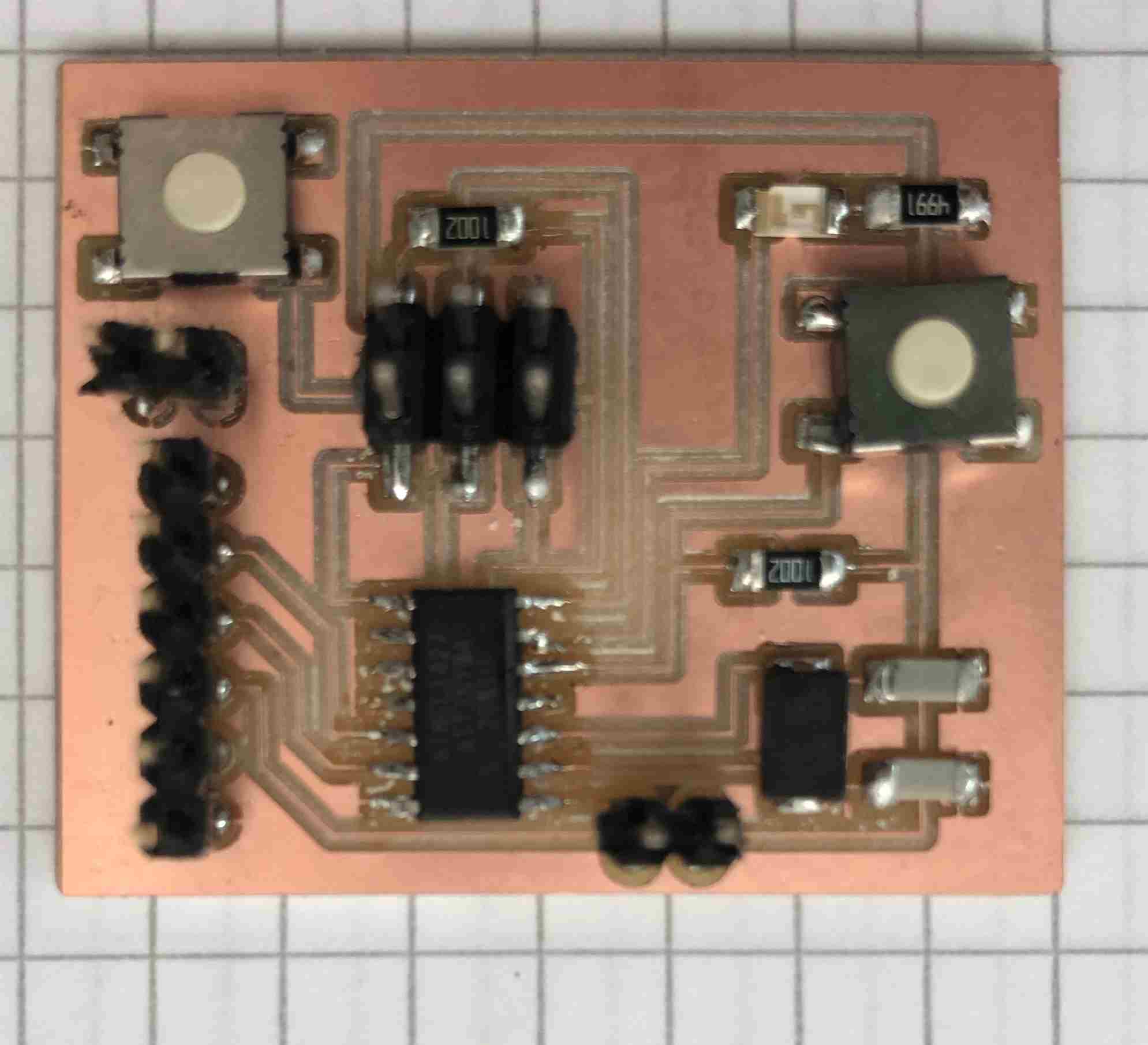
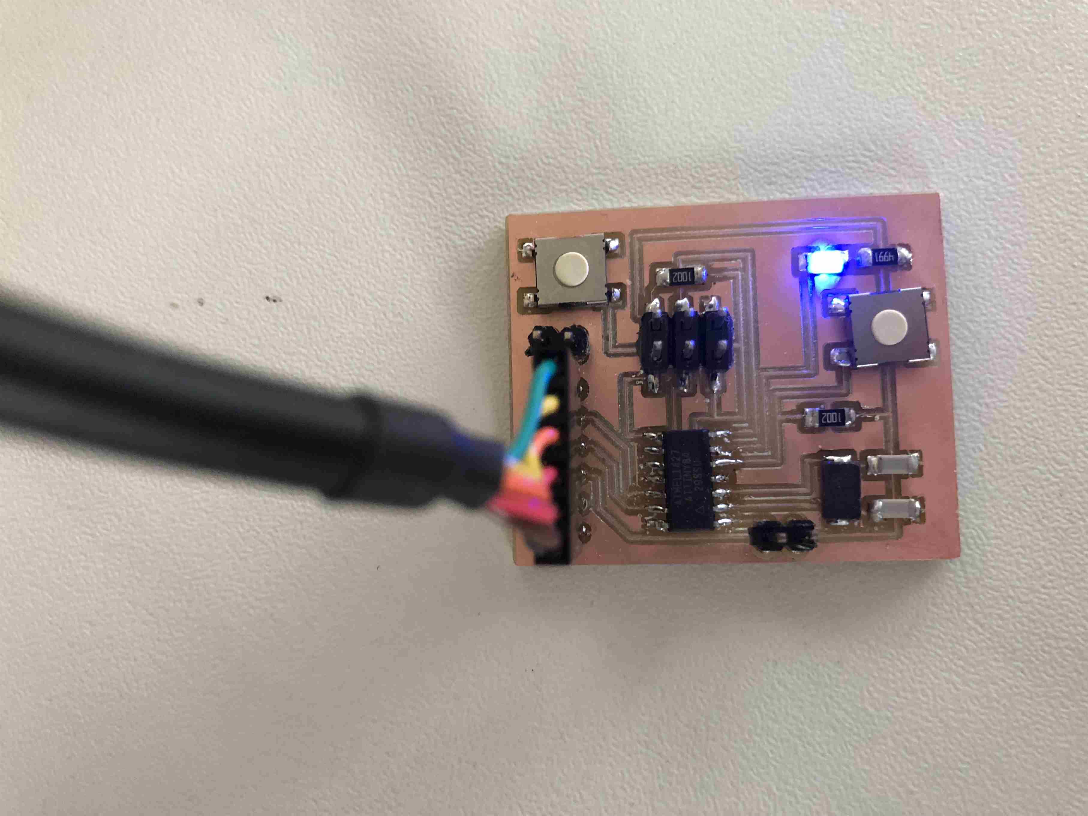
Result of my Hello board.
After spending some time to find the optimization of my board and it comes to the result that I am not using any 0 ohm resistor witha compact board.
Open this website,Fabmodules.org to make the GCode.
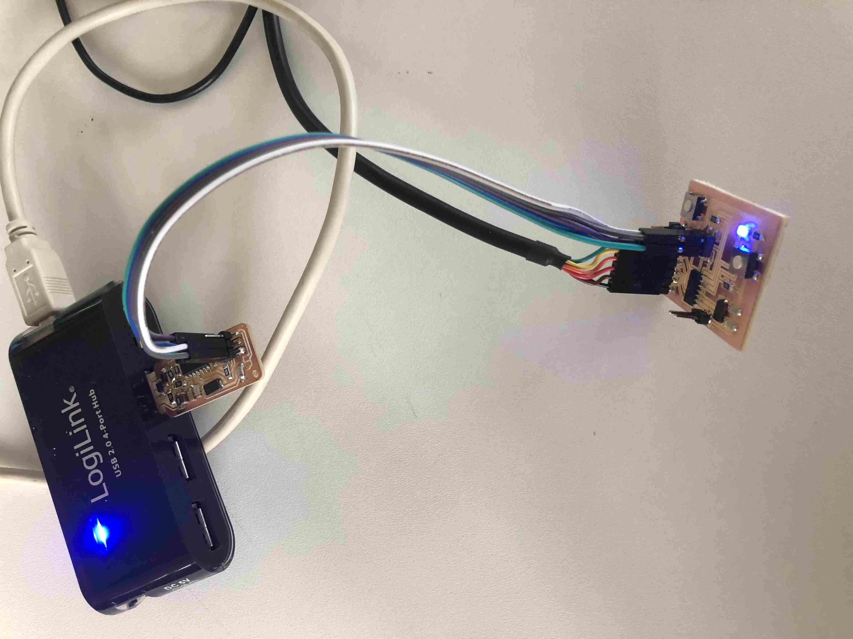
7. Test the hello board
Connect the AVR ISP to your FAB ISP except the 5V and connect the FDTI cable to power the board.
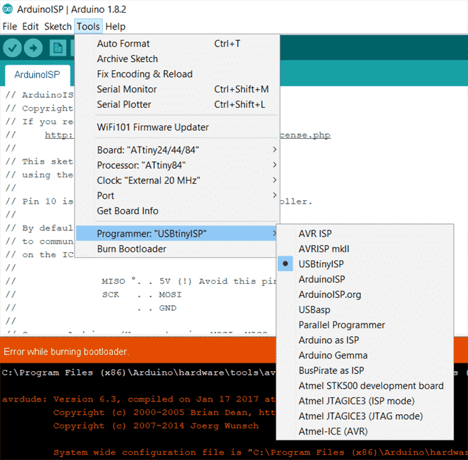
After select all the options like above, and connect the usb ports to your computer, click Burn bootloader.
Download
Hello board.