Contents
Embedded programming
1. Introduction to C
2. Input and Output
3. Program and Microcontroller
4. Examples
In this page you will learn the common problem using a mechanical switch and how to overcome this issue using embedded programming.
Embedeed Programming
An embedded system contains a microcontroller to accomplish its job of processing system inputs and generating system outputs. The link between system inputs and outputs is provided by a coded algorithm stored within the processor's resident memory. What makes embedded system design so interesting and challenging is the design must also take into account the proper electrical interface for the input and output devices, limited on-chip resources, human interface concepts, the operating environment of the system, cost analysis, related standards, and manufacturing aspects. [From Barret 2010, 00/TWQ 82]
An embedded system is a computer system designed for specific control functions within a larger system, often with real-time computing constraints. It is embedded as part of a complete device often including hardware and mechanical parts. By contrast, a general-purpose computer, such as a personal computer (PC), is designed to be flexible and to meet a wide range of end-user needs. Embedded systems control many devices in common use today. Source: From Wikipedia, retrieved on 24.11.2012
1. Introduction to C
C programming.
1.1 Unit Objective
The objectives of this chapter is how to write simple C programming with input and output.
1.2 Standard C program example:
                            #include <avr/io.h	>

                            void main(void) {

                              DDRD 	&= ~(1<<DDD2);  // PD2 as Input

                              DDRD 	&= ~(1<<DDD3);  // PD3 as Input


                              PORTD |= (1<<PD2);  // Pullup PD2

                              PORTD |= (1<<PD3);  // Pullup PD3


                              DDRB |= (1<<DDB1);  // PB1 as Output

                              while(1)  {


                                if((~PIND 	& (1<<PD2)) 	&	& (~PIND 	&(1<<PD3))) // Button 1 and 2 pressed

                                     PORTB |= (1<<PB1);   // LED is on

                                else

                                     PORTB 	&= ~(1<<PB1);   // Else LED is off  } }
1.3 C Basics
Set, clear and toogle a bit
Set a bit
BYTE |= (1<<i);
Clear a bit
BYTE &= ~(1<<i);
Toogle a bit
BYTE ^= (1<<i);
2. Input and Output
2.1 Unit Objective
The objective of this unit is to write a c programming and initialize the port of attiny84 as an input and output and upload it to the
2.2 Initial instalation
Let's get started!
Make File
                                PROJECT=main

                                SOURCES=$(PROJECT).c

                                MMCU=attiny84

                                MCU=t84

                                F_CPU = 20000000


                                CFLAGS=-mmcu=$(MMCU) -Wall -Os -DF_CPU=$(F_CPU)


                                $(PROJECT).hex: $(PROJECT).out

                                     avr-objcopy -O ihex $(PROJECT).out $(PROJECT).c.hex;\

                                     avr-size --mcu=$(MMCU) --format=avr $(PROJECT).out


                                $(PROJECT).out: $(SOURCES)

                                     avr-gcc $(CFLAGS) -I./ -o $(PROJECT).out $(SOURCES)


                                program-bsd: $(PROJECT).hex

                                     avrdude -p $(MCU) -c bsd -U flash:w:$(PROJECT).c.hex


                                program-dasa: $(PROJECT).hex

                                     avrdude -p $(MCU) -P /dev/ttyUSB0 -c dasa -U
  flash:w:$(PROJECT).c.hex


                                program-avrisp2: $(PROJECT).hex

                                     avrdude -p $(MCU) -P usb -c avrisp2 -U
  flash:w:$(PROJECT).c.hex


                                program-avrisp2-fuses: $(PROJECT).hex

                                     avrdude -p $(MCU) -P usb -c avrisp2 -U lfuse:w:0x5E:m


                                program-usbtiny: $(PROJECT).hex

                                     avrdude -p $(MCU) -P usb -c usbtiny -U
  flash:w:$(PROJECT).c.hex


                                program-usbtiny-fuses: $(PROJECT).hex

                                     avrdude -p $(MCU) -P usb -c usbtiny -U lfuse:w:0x5E:m


                                program-dragon: $(PROJECT).hex

                                     avrdude -p $(MCU) -P usb -c dragon_isp -U
  flash:w:$(PROJECT).c.hex


                                program-ice: $(PROJECT).hex

                                     avrdude -p $(MCU) -P usb -c atmelice_isp -U
  flash:w:$(PROJECT).c.hex
Open and edit the make file according to your microcontroller for example for me I am using attiny 84.
main.c
                                #include <avr/io.h>

                                int main(void){

                                    DDRB &= ~(1<<DDB2); // PD3 as Input

                                    DDRA |= (1<;<;DDA7); //PA7 as Output


                                    PORTB |= (1<<PB2); //Pullup PB2


                                   while (1) {

                                     if ((~PINB & (1 << PB2))); //button is pressed

                                          PORTA |= (1<<PA7); // LED is on

                                     else

                                          PORTA &= ~(1<<PA7); ; Else LED is off


                                   }

                                }
Description:
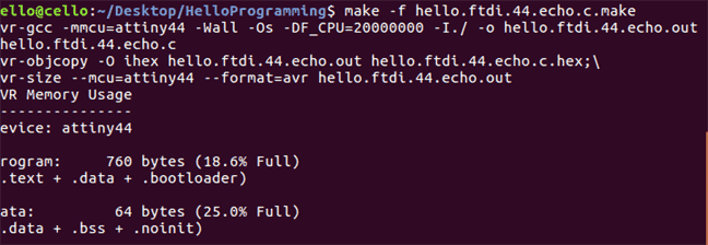
1. Make makefile.
$ make -f makefile.make
Out:
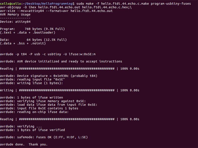
2. Make fuse.
This is only done once, skip this step if you have done it.
$ sudo make -f makefile.make program-usbtiny-fuses
Out:
3. Upload the c program in the main.c file.
$ sudo make -f makefile.make program-usbtiny
Out:
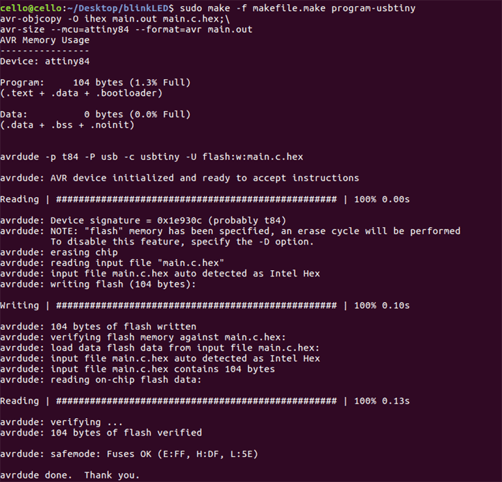
This is the result if you have made it successful.
Download files:
Make file
Main.c
2.3 Task 1
init.c file
                                           /*
                                            This file contains all init steps in one function.
                                            To call this function just use init();
                                            */


                                            #include 	<avr/io.h>

                                            #include "init.h"


                                            void init(void){


                                                DDRD &= ~(1 < < DDD2); // set PD2 data direction to input

                                                DDRD &= ~(1 < < DDD3); // set PD data direction to input


                                                PORTD |= (1 < < PD2); // enable internal pullup for PD2

                                                PORTD |= (1 << PD3); // enable internal pullup for PD3


                                                DDRB |= (1 < < DDB1); // set PB1 data direction to output

                                                DDRB |= (1 < < DDB2); // set PB2 data direction to output

                                                DDRB |= (1 < < DDB3); // set PB3 data direction to output


                                            }
main.c file
                                            #include <avr/io.h	>

                                            #include "init.h"


                                            int main(void){


                                                init ();


                                                while(1){


                                                    if ((~PIND & (1 << PD2)) && (~PIND & (1 << PD3))) {	//if PD2 and PD3 are pressed

                                                         PORTB &= ~(1 << PB1);	// turn led 1 off

                                                         PORTB |= (1 << PB2);	// turn led 2 on

                                                         PORTB &= ~(1 << PB3);	// turn led 3 off

                                                    }

                                                    else if ((~PIND & (1 << PD2)) || (~PIND & (1 << PD3))) {//if PD2 or PD3 is pressed

                                                         PORTB |= (1 << PB2);	// turn led 2 on

                                                         PORTB |= (1 << PB3);	// turn led 3 on

                                                         PORTB &= ~(1 << PB1);   // turn led 1 off


                                                    }


                                                    else

                                                         PORTB |= (1 << PB1);	// turn led 1 on

                                                         PORTB &= ~(1 << PB2);	// turn led 2 off

                                                         PORTB &= ~(1 << PB3);	// turn led 3 off


                                                }


                                                return 0;


                                            }
Description:
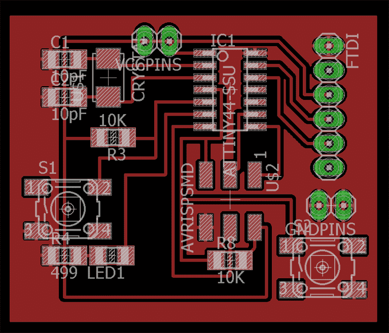
2.5 The PCB board
The board that I used this week is the board that I fabricated before and it is documented on the 6th exercise. It has a button and an LED.
Datasheet AT Tiny 84
I have checked the data sheet of AT Tiny 84 and this is the pinout of the microcontroller.
3. Program and Microcontroller
3.1 Code analysis
                          void main (void){


                              }
Main is the name of the function any program must have. Program executes the main function, and other functions are used only if function main() calls them!
DDRD stands for Data Direction Register D. Notice that microcontroller has 3 groups of digital input output pins: D,B, C.
3.3 What is register?
It is a part of the memory the device has. But it is not just a memory for any information: every register has very specific function, which is always hinted by the name of the register.All registers in Atmega84 are 8bit long. 0000 0000 or 1111 1111,etc
PORTD |= (1 < < PD2);
The button is disconnected when it is not pressed and when it is pressed you close contact supplying low voltage to the connected pin which is called active low.
Let us define an input device of a button to pins D2.
1 < < DDD1 means to place a 1 to the position corresponding to D2 pin: DDRD = 0000 0100
~( A ) means to invert the variable A , all 0's become 1's and vice versa: 1111 1011
B & = C is a bitwise AND, which will keep the value of the bits in B, if C has a 1 at their position and make them 0 if C has 0 in their position. C is a so called mask.
The input is connected to Vdd, logical1 , throught he pullup resistor when the witch is open
Why should have 0 in the bits of DDRD corrsponding to D2 because specification specifies that zeros in DDRs are for input.
Now let set port B as an output of a LED.
Set a biwise OR |= of a a set one bit of aregister to 1 or high
More about the port operations in AVR.
3.3 While(1) and if(expression)
While (1) means an infinite loop and will run forever whithin the curly brackets.
If expression, if( (~PIND & (1 < < PD2)) && (~PIND & (1 < < PD3)) )
If both buttons are pressed this expression will be true and the whole expression within the brackets will be evaluated.
4. Examples
4.1 Blinking LED
main.c
                                #include <avr/io.h>

                                int main(void){

                                    DDRB &= ~(1<<DDB2); // PD3 as Input

                                    DDRA |= (1<;<;DDA7); //PA7 as Output


                                    PORTB |= (1<<PB2); //Pullup PB2


                                   while (1) {

                                     if ((~PINB & (1 << PB2))); //button is pressed

                                          PORTA |= (1<<PA7); // LED is on

                                     else

                                          PORTA &= ~(1<<PA7); ; Else LED is off


                                _delay_ms(1000);


                                   }

                                }
Description:
width="320" height="240"Download
click progarm c
make file
4.2 Switch bounce
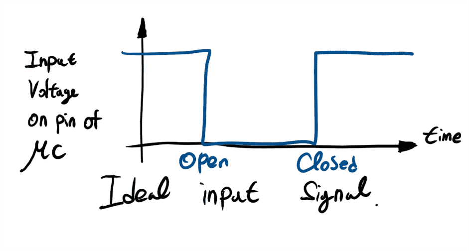
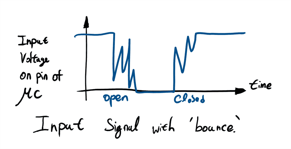
We have almost finished with inputs but there is one unpleasant feature that you need to be aware of switch bounce. The contacts of a switch are mechanical. When the switch is operated they do not open or close cleanly but vibrate for a while. This causes the contacts to open and close several times, each time the switch is operated.
Input signal with 'bounce'. This typically lasts for around 50 ms. It can be eliminated by using extra components or (more usually) in software
Debouncing
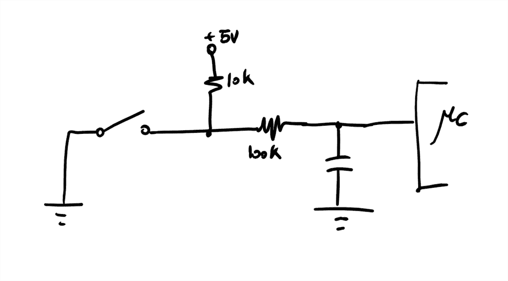
Problem: Buttons, as well as switches described on previous slide, are prone to signal spikes after the press. It can result in many readings per one actual click. The possible hardware solution would be RC circuit: Here the signal noise, which has high frequency, is filtered by capacitor. However, it would be a lot easier if we can solve the problem in the software!
4.3 Button with action qulifier of set
In this exercise we will have one input and one output. The LED as an output will turn on once the button is clicked and to turn off the LED once the button has to be clicked again. To program this, we will use a state space machine.
main.c
                                #include <avr/io.h>

                                #include  <util/delay.h>


                                void init(void){

                                     //set inputs and outputs

                                     DDRB &= ~(1<<DDB2); // PD3 as Input

                                     DDRA |= (1<<DDA7); // PA7 as Output


                                     PORTB |= (1<<PB2); // Pullup PB2

                                }


                                int main(void){


                                    //state

                                    int state=0; //starting with state 0 and wait for the button to be pressed


                                    int debounceTicks = 50; // delay of millisec that have to pass by before a click and it is assumed to be safe


                                   while (1) {

                                     //starting with state 0

                                    i f (state ==0) { // waiting a button to be pressed

                                          if ((~PINB & (1 << PB2))){ //button is pressed

                                               _delay_ms(debounceTicks);

                                               state =1;

                                          }

                                    }else if(state ==1){

                                         _delay_ms(debounceTicks);

                                          if ((PINB & (1 << PB2))){ //button is not pressed

                                               state=2;

                                          }


                                    }else if(state ==2){

                                         click();

                                         state =0;

                                    }
Video
State machine diagaram
Download
click progarm c
make file
4.4 Arduino IDE, Button program for click, double clicks and long press.
I used an arduino IDE to program this using a state machine.
The advantages of using arduino IDE is that it has a core set of library functions that control the peripheral hardware of whatever microcontroller you are using. In pure C, you need the datasheet for the specific microcontroller your are using. It requires more work, more reading, more coding and more debugging but the resulting progam will probably be smaller and more efficient.
In this chapter, we are going to program to do something when the buton is click, double clicks and long pressed.
The board that I used is modified from Satshakit-128. I have added one button and a LED.
The LED 1 will toogle once it is click, the LED 2 will toogle once the button is double clicked and if the button is pressed in long term, LED 3 will turn on for one second.
Above is the code for having click, double clicks and long pressed using a state space machine.
// Input pin
int button =0; // select the pin for the button

// Output pin
int ledPinYes = 13;   // select the pin for the YES LED  change the click function, pin 13
int ledPinNo = 12;   // select the pin for the No LED  change the double click function, pin 12
int ledPinNope = 11;   // select the pin for the Nope LED pin 11

// Input Values
boolean buttonState = false; // choose the input pin (for a pushbutton)
unsigned long now = millis(); // current (relative) time in msecs.

//State
int _state = 0; // starting with state 0: waiting for button to be pressed
unsigned long _startTime; // will be set in state 1
unsigned long _stopTime; // will be set in state 1

int _debounceTicks = 50;      // number of millisec that have to pass by before a click is assumed as safe.
int _clickTicks = 300;        // number of millisec that have to pass by before a click is detected.
int _pressTicks = 2000;       // number of millisec that have to pass by before a long button press is detected.


//led state to toogle
boolean stateLedYes;
boolean stateLedNo;


void setup() {
  // put your setup code here, to run once:
   pinMode(ledPinYes, OUTPUT);  // declare the ledPin as an OUTPUT
   pinMode(ledPinNo, OUTPUT);  // declare the ledPin as an OUTPUT
   pinMode(ledPinNope, OUTPUT);  // declare the ledPin as an OUTPUT
   pinMode(button, INPUT); // declare the button as an INPUT
   Serial.begin(9600);

}

void loop() {
  // put your main code here, to run repeatedly:
  buttonState = digitalRead(button);  // read input value
  now= millis(); // update variable now
      //Starting (State 0)
    if (_state == 0) { // waiting for One pin being pressed.
      if ( buttonState == false) { //if button is pressed

         _state = 1; // step to state 1

         _startTime = now; // remember starting time

         Serial.println("state 0!");
      }

    }else if(_state == 1) { // waiting for One pin being released.
       Serial.println("state 1!");
       Serial.print("Start time:");
       Serial.println(_startTime);
       Serial.print("now:");
       Serial.println(now);
       if ((buttonState == false) && (now > _startTime + _pressTicks)) { // /if button is pressed and pressed too long
         _state = 6; // step to state 6

       }else if(buttonState == true) { // if button is not pressed
          delay(_debounceTicks);
          _state = 2;
          _stopTime = now; // remember stopping time
       }else if((buttonState == true) &&  ((unsigned long)(now - _startTime) < _debounceTicks)){
          Serial.println("State1 Debouncing");
        // button was released to fast means that this is debouncing
          _state =0;
       }else{
        //wait. Stay in this state
       }


    }else if(_state == 6) { // waiting for One pin being release after long press.
        toogleNopeLED();
        //Serial.println("state 6!");
        if (buttonState == true) { // button is not pressed
          _state = 0; // restart.
          //Serial.println("state 6!released");
        }
    }else if(_state ==2){
        if (now > _startTime + _clickTicks ) {
        // this was only a single short click
        //Serial.println("state 2!");

        click(); //toggle LED yes LED

        _state = 0; // restart.
       }else if ((buttonState == false)&& ((unsigned long)(now - _stopTime) > _debounceTicks) ){
          _startTime = now; // remember starting time
          _state =3;


       }
    }else if(_state ==3){
      if(  buttonState == true){// button release and this is double click

        doubleClick();
        Serial.println("state 3!");
        //Serial.println("Double Click!");
         _startTime = now; // remember starting time
         delay(_debounceTicks); //debouncing delay
        _state = 0; // restart.

      }else if((buttonState == true) && ((unsigned long)(now - _startTime) < _debounceTicks)){
        // button was released to fast means that this is debouncing
          _state =0;
       }


    }
}

void click(void){
  //PORTD ^= (1<<ledPinYes); //toogle led yes
  digitalWrite(ledPinYes, (stateLedYes) ? HIGH : LOW);
  stateLedYes = !stateLedYes;
  delay(100);
  Serial.println("Click!");
}

void doubleClick(void){
  digitalWrite(ledPinNo, (stateLedNo) ? HIGH : LOW);
  stateLedNo = !stateLedNo;
  delay(100);
  Serial.println("Double Click!");
}


void toogleNopeLED(void){

  digitalWrite(ledPinNope, HIGH);  // turn LED ON
  delay(1000);
  digitalWrite(ledPinNope, LOW);  // turn LED ON

}
The board that I used in this video is the satshakit-128 board that I milled in the fabLab.
Download
Arduino IDE click,double clikcs and long press program.