Final Project ( process )
go to ” Final Project “
INDEX ( jump to the sub-systems )
Wk00 (2020/01) “Beginning”
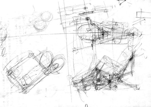
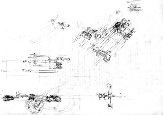
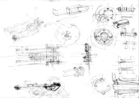
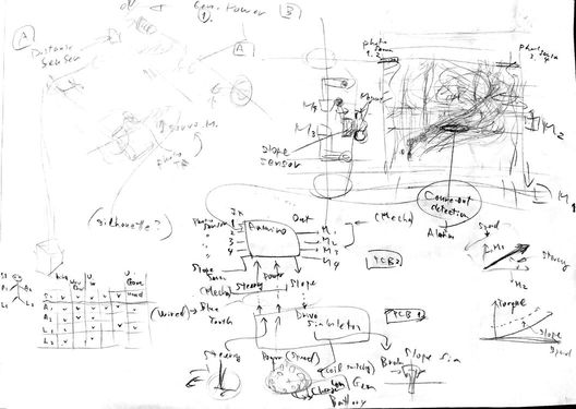
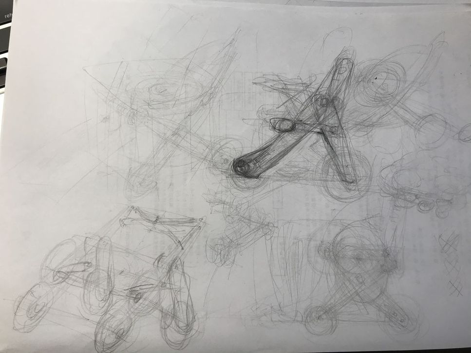
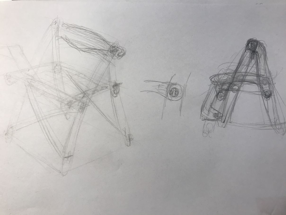
1) sketches 2020/01
 |
 |
 |
 |
Wk01 (2020/01/29) “Planning”
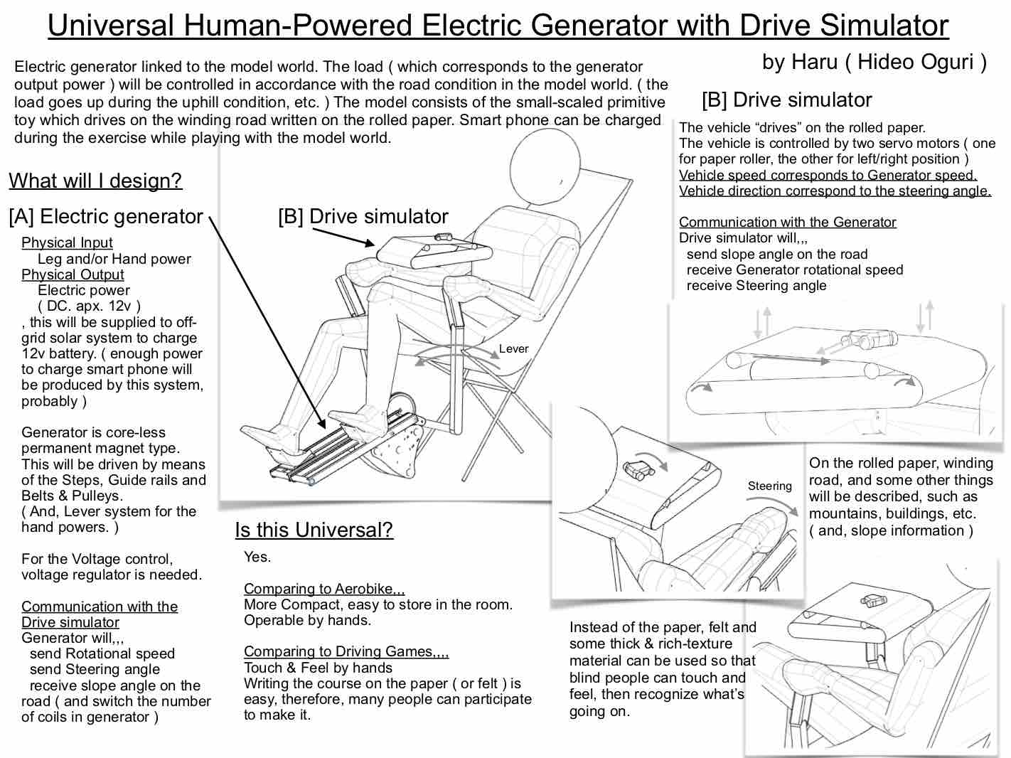
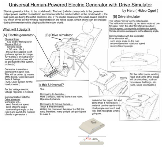
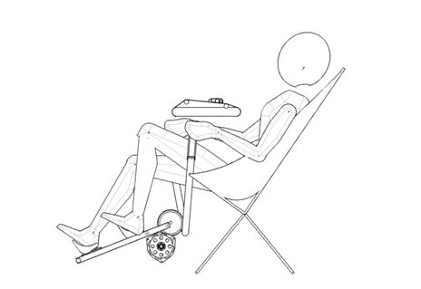
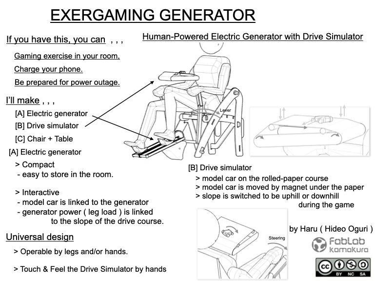
1) What this will do and who will use this?
- This will be used as an electric generator while people get some exercise moving their legs and/or arms.
- Also, the drive simulator motivates ( simple toy car on the rolled paper ) the people to continue the exercise.
- Various people can use this. Two legs, two arms, one leg & one arm, etc. If the drive simulator consists of the thick & rich-texture materials like felt, blind people can touch and feel it.
Wk02 (2020/02/05) “3D modeling”
1) Modeling by fusion360
- I’ll use fusion360 to proceed my final project, because this system has necessary functions such as 2D sketch, 3D modeling, assembles, joints, etc.
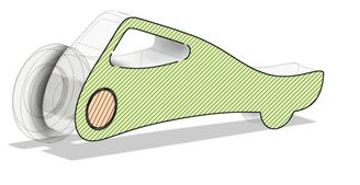
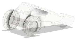
- Then, I made simple model of my final project, which shows some outline of the project. The details will be designed later in accordance with this fab academy course.
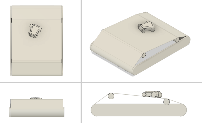
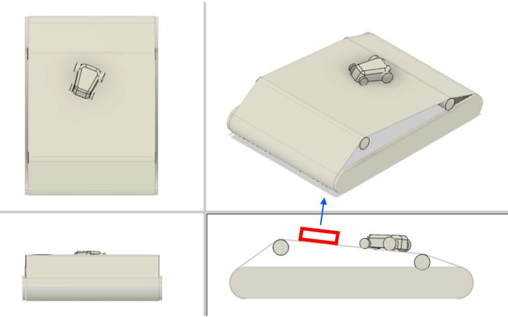
overview
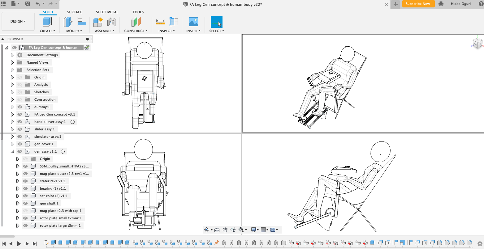
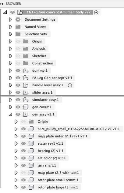
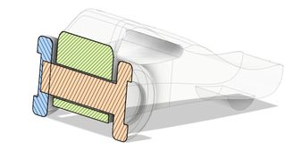
tree-structure of the components, and the drive simulator
generator and slider ( corresponds to the pedals of bicycle )
generator ( axial flux generator )
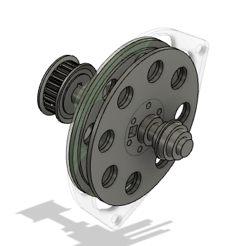
| shaft, bearing, pulley | rotor, stater |
|---|---|
 |
 |
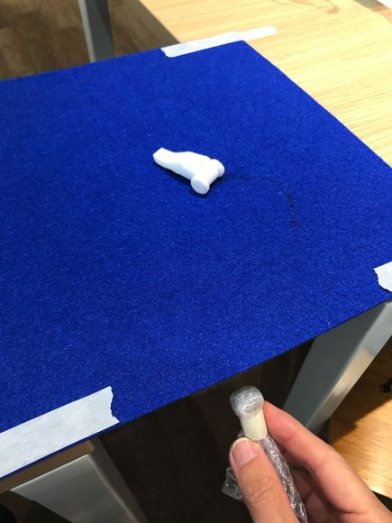
Wk03 (2020/02/12) “Pop-up item on Drimve-simulator”
I made this fusion360 sketch.
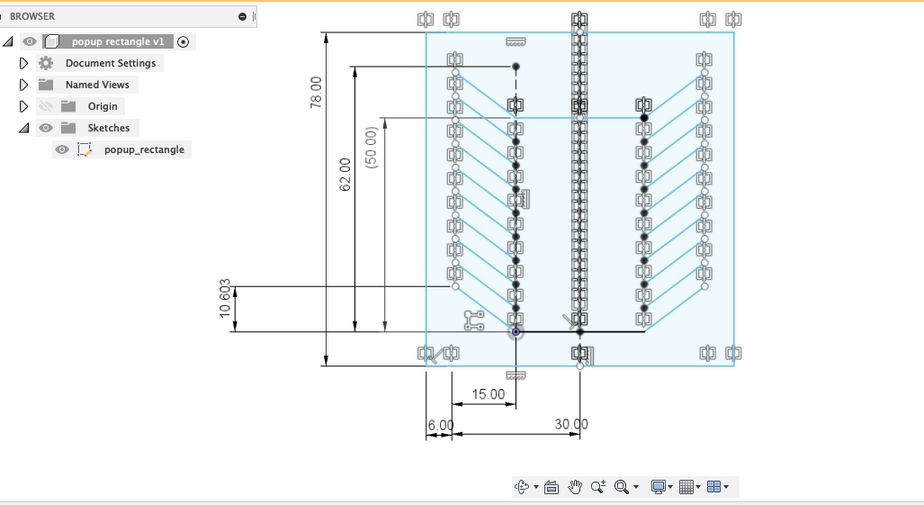
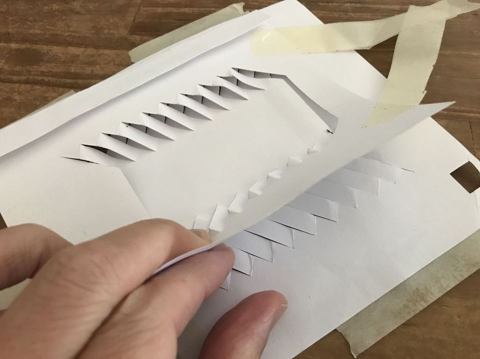
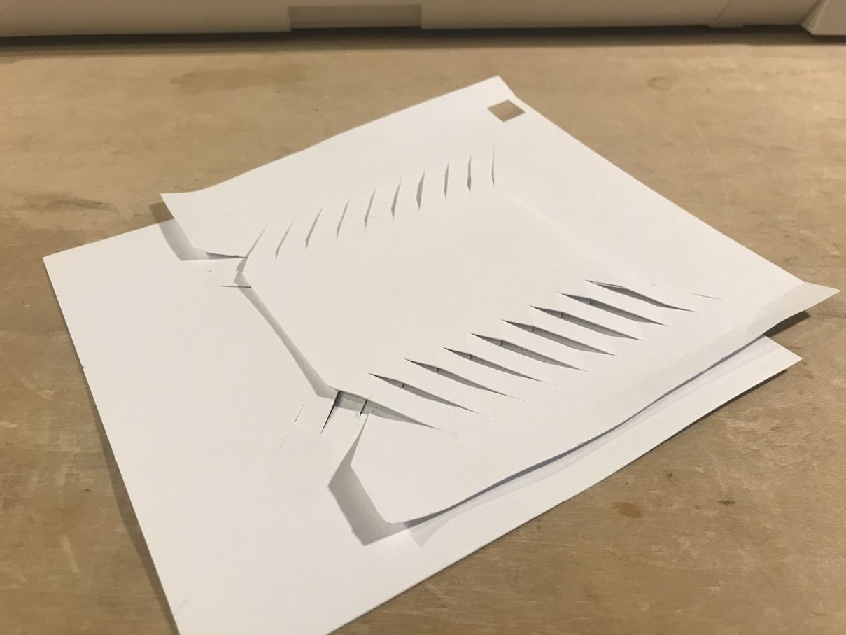
Cut two pieces by the vinyl cutter ( CAMEO / silhouett ).
( one is about 20% smaller than the other. )
Combine two of them with Double-sided tape.
| Cut two pieces | Combine two of them |
|---|---|
 |
 |
 |
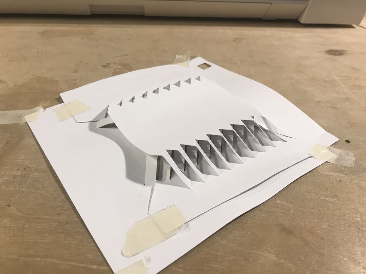 |
Then, by sliding the paper edge, the center rectangle pops up.
This can be utilized for the haptic function on Drive-Simulator.
Project Management

Wk05 (2020/02/26) “3D-Printing the Model-Car”
This week’s assignment was “scanning and printing”.
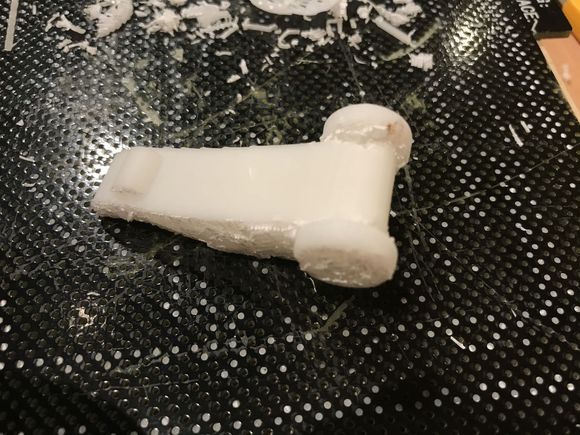
I prepared the fusion360 file of ” model car ” which will be used as the part of my Final Project. This is a simple small car with two rear wheels with a shaft. The wheels and the shaft are connected and there is an appropriate clearance between the shaft and the body, so that the wheels can rotate.
 |
 |
 |
 |
Considering the result of the group assignment, the clearance was set to be 0.2 mm.
( In the above right photo, the pink and blue colored “wheel + shaft” are printed as one piece. )
1) printing and finishing
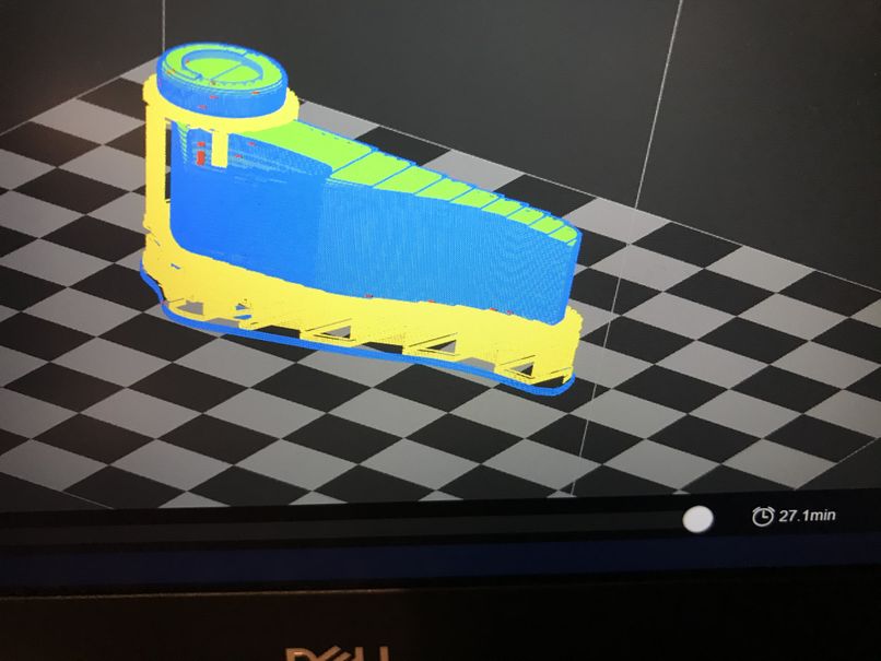
In the preview window, the support material is shown as yellow, which is distributed in between wheel and body.
| print preview, estimated time = 27 minutes | printed object |
|---|---|
 |
 |
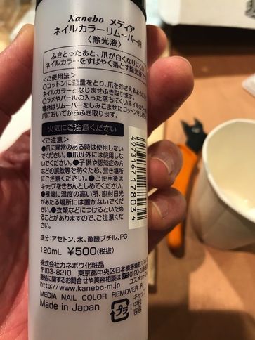
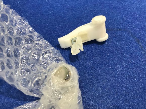
To remove the support material, I used “nail-color remover” which contains acetone.
| “nail-color remover” with acetone | put the wheel portion in acetone |
|---|---|
 |
 |
It was almost successful, but the wheel rotation was very sticky.
After about 10 hours, the material was dried, carefully rotate the wheels, then the rotation became smoothly.
2) test for the Final Project
Taking this opportunity, I made the car for the simulator which will move on the table of the simulator.
I put one small washer under the body, and drag the car by using a magnet in the backside of the table. While the car is moving, the wheels were turning by the friction with the felt on the table.
| small washer under the body | drag the car by using a magnet |
|---|---|
 |
 |
As the first trial, the result was successful.
Wk07 (2020/03/11) “CNC - Chair”
This week’s assignment was “Computer-Controlled Machining”.
1) modeling by fusion360
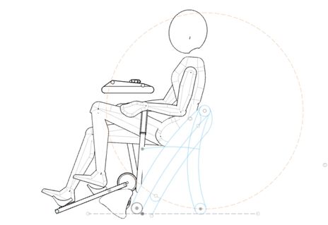
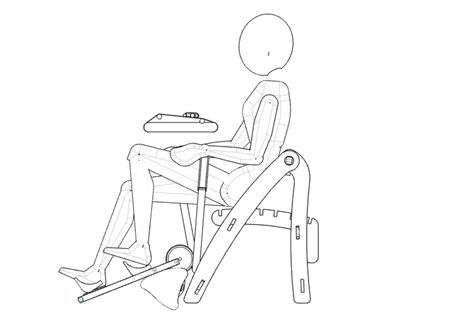
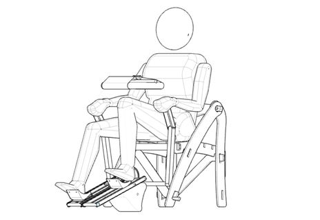
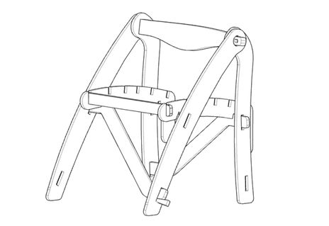
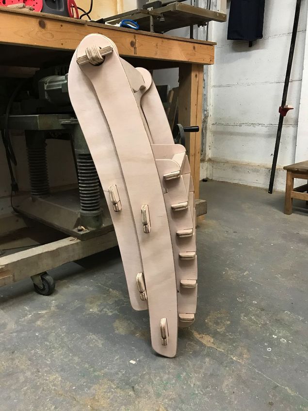
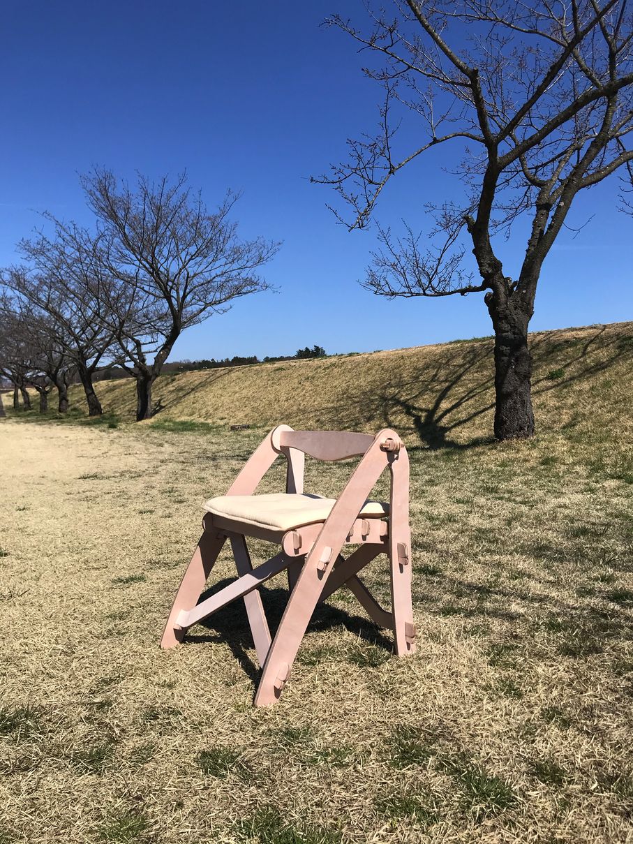
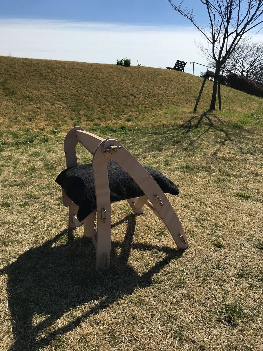
I decided to make a chair for my Final Project, considering the transportation, this should be folding type, and as light as possible.
| sketch (about 2 days before the CNC session ) | |
|---|---|
 |
 |
And, I changed the operator’s posture and the drive simulator position, so that he/she easily observe the drive simulator.
| before | after |
|---|---|
 |
 |
| modeling almost completed | |
|---|---|
 |
 |
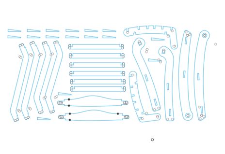
| completed | “NESTER” add-in was used to align the parts on one plane. |
|---|---|
 |
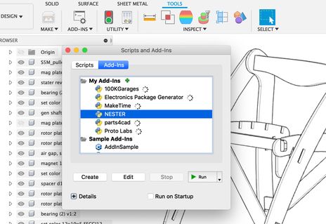 |
converted to .dxf file
2) making CAM-toolpath
3) milling
Please refer the individual assignment page for the details.
Wk07 - Computer-Controlled Machining, CAM-toolpath, milling
4) assembling
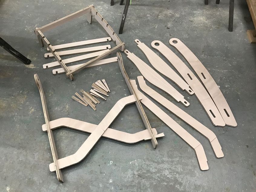
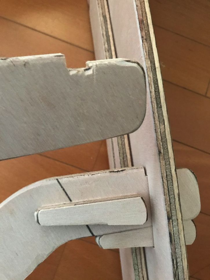
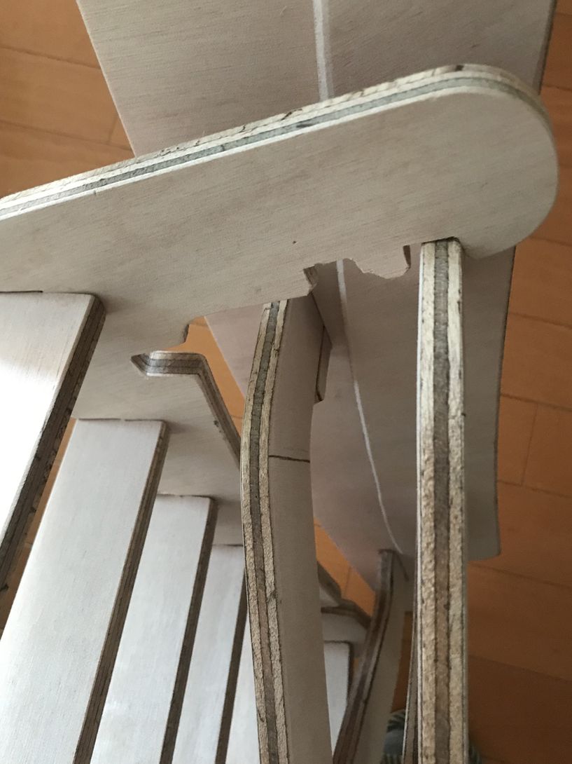
some connecting portions were modified/repaired by hand file.
| notch was added to avoid the element come off from the insertion | also, notch to hang the seat assembly when the seat is fold |
|---|---|
 |
 |
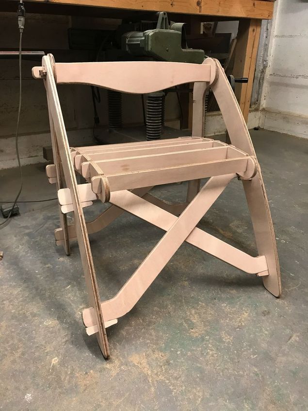
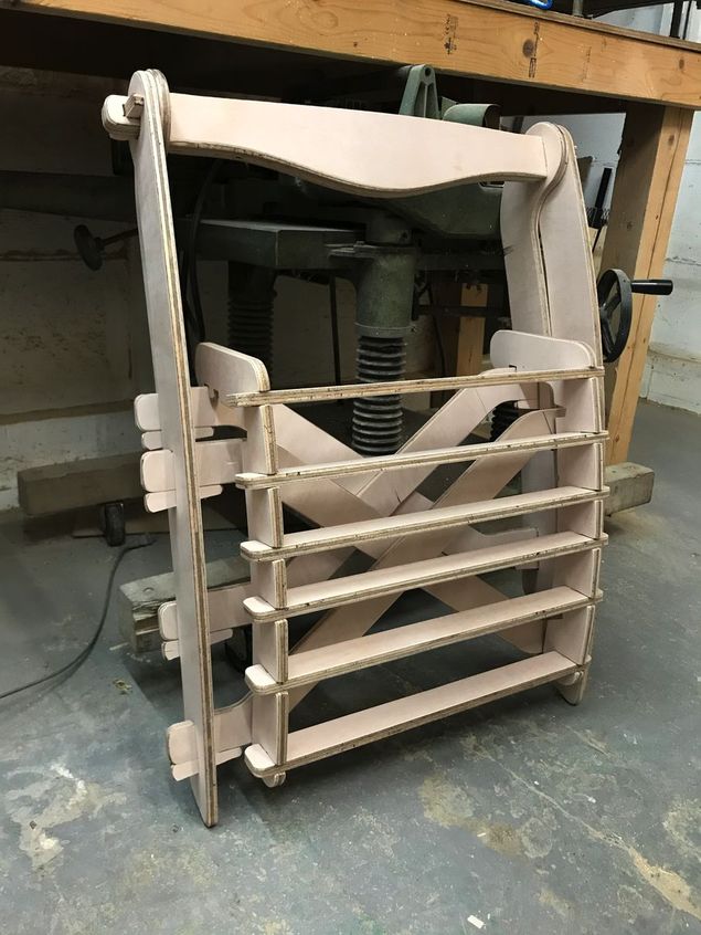
assembly work completed. ( it took about 7 hours. )
 |
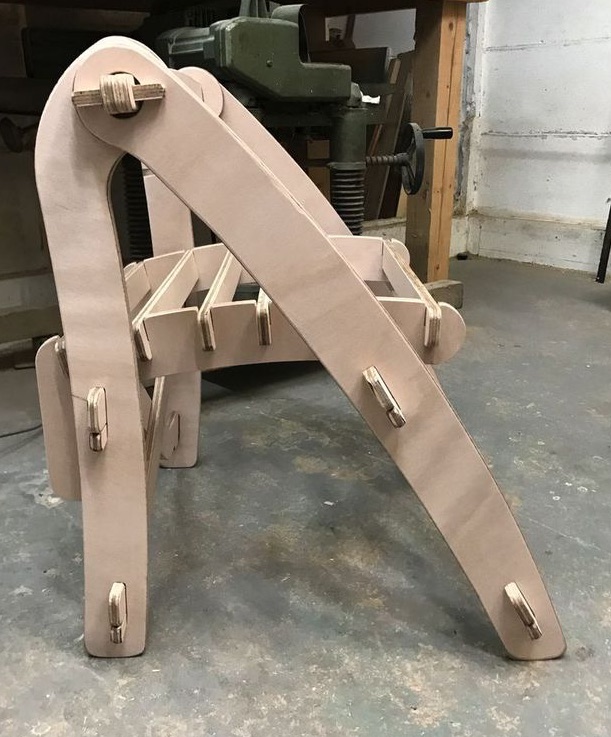 |
| folding condition | |
|---|---|
 |
 |
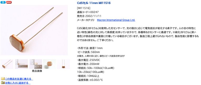
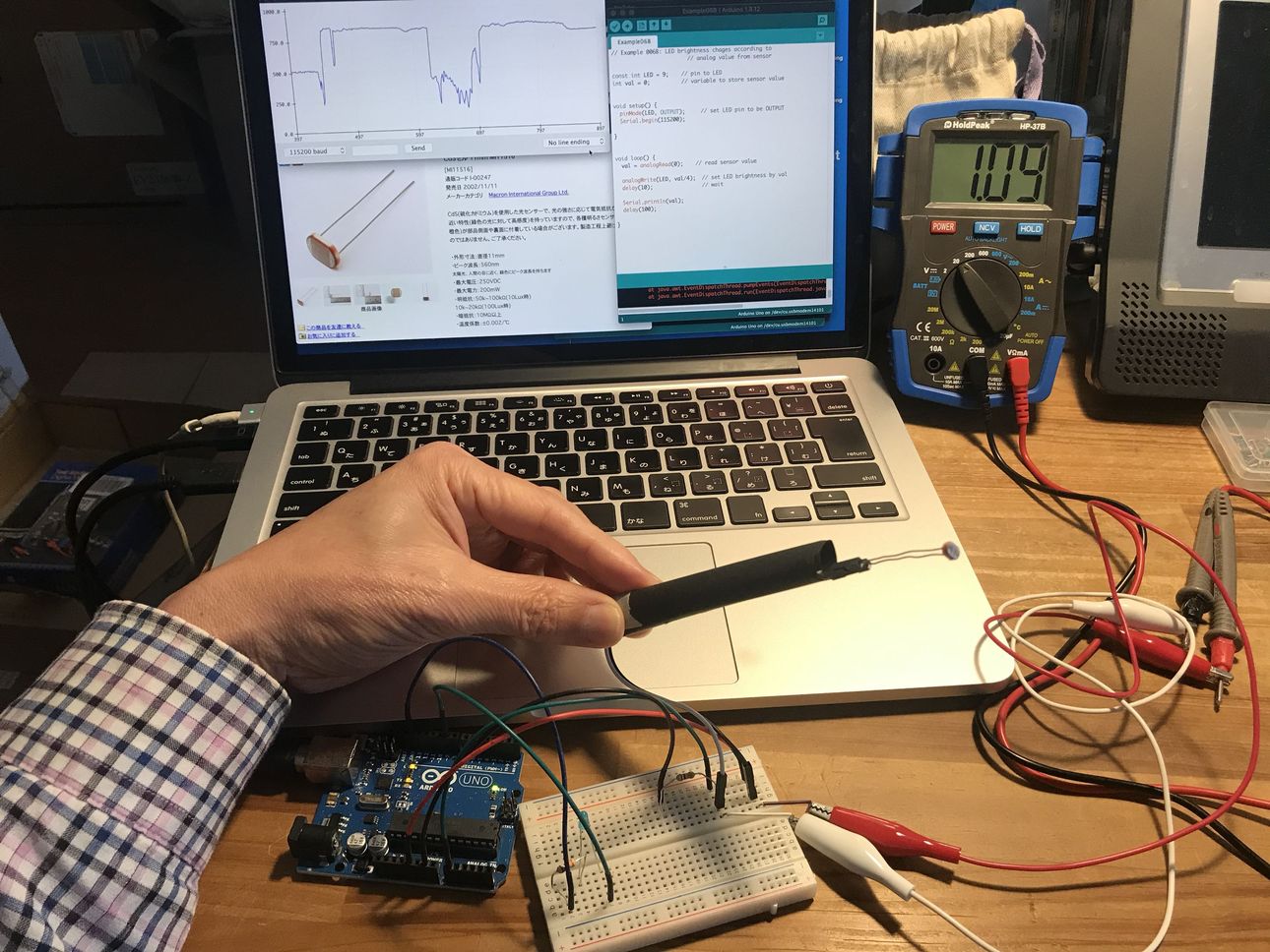
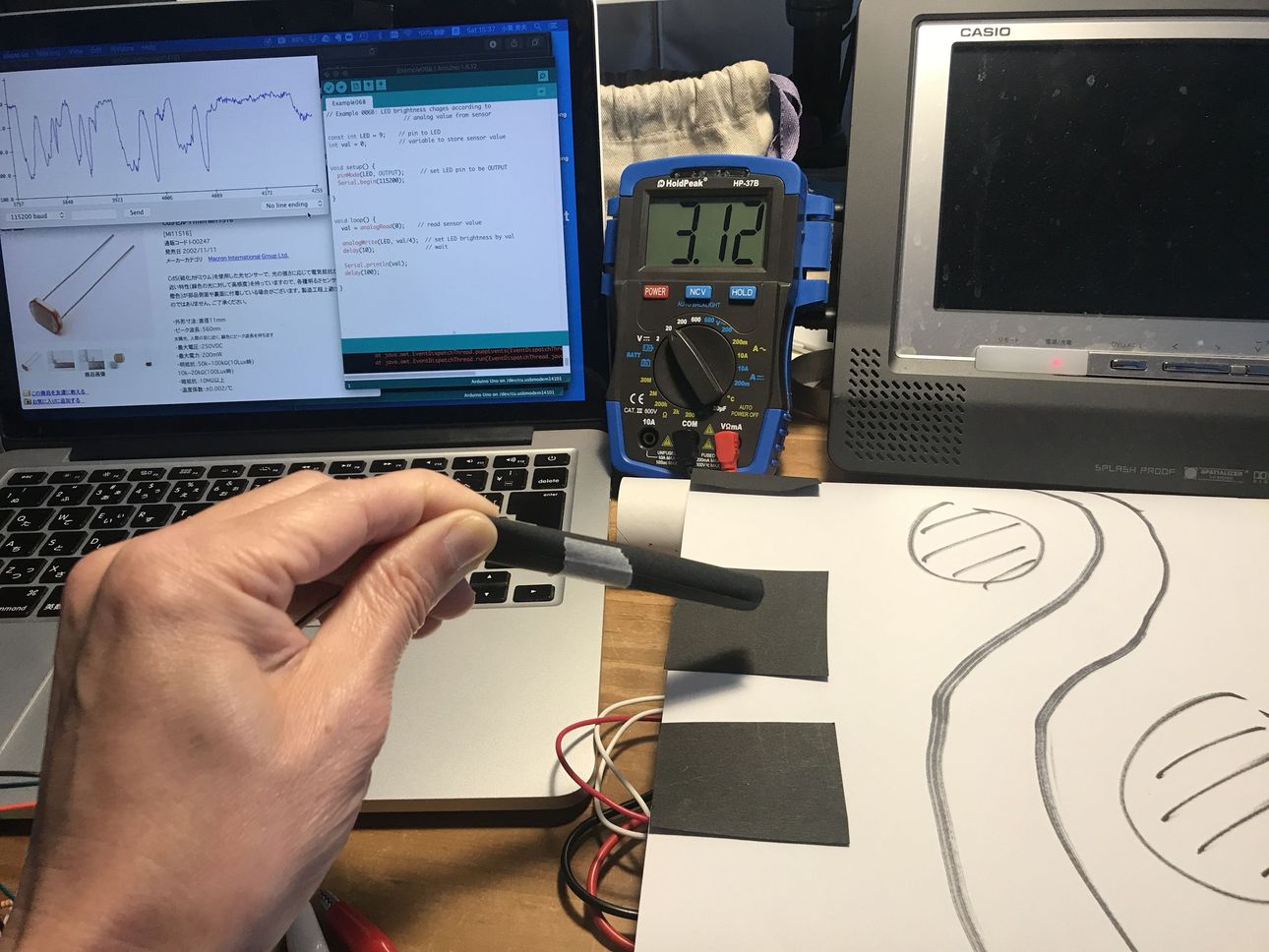
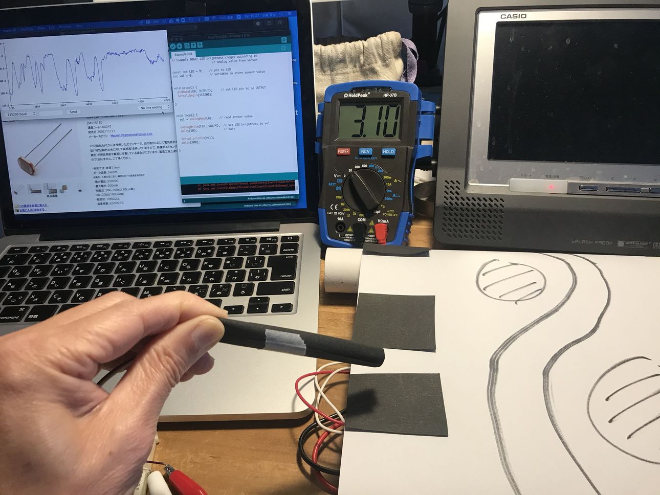
Wk09 (2020/03/25) “Drive Simulator, slope sensing”
 |
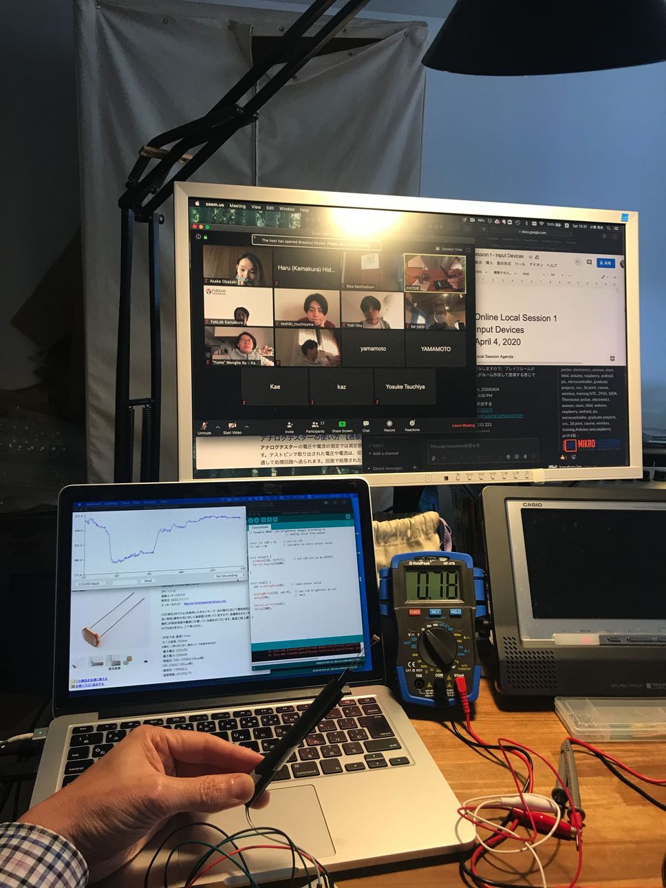 |
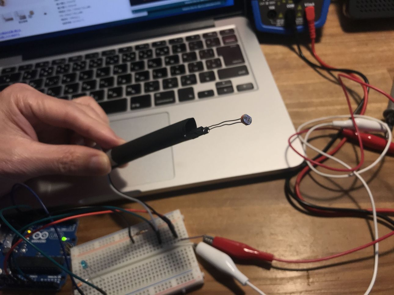
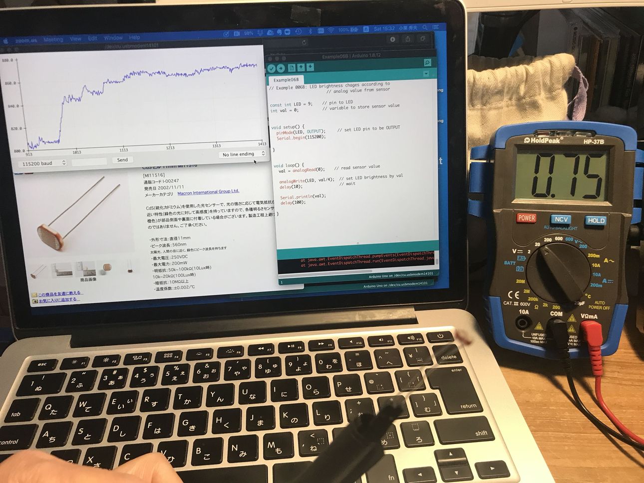
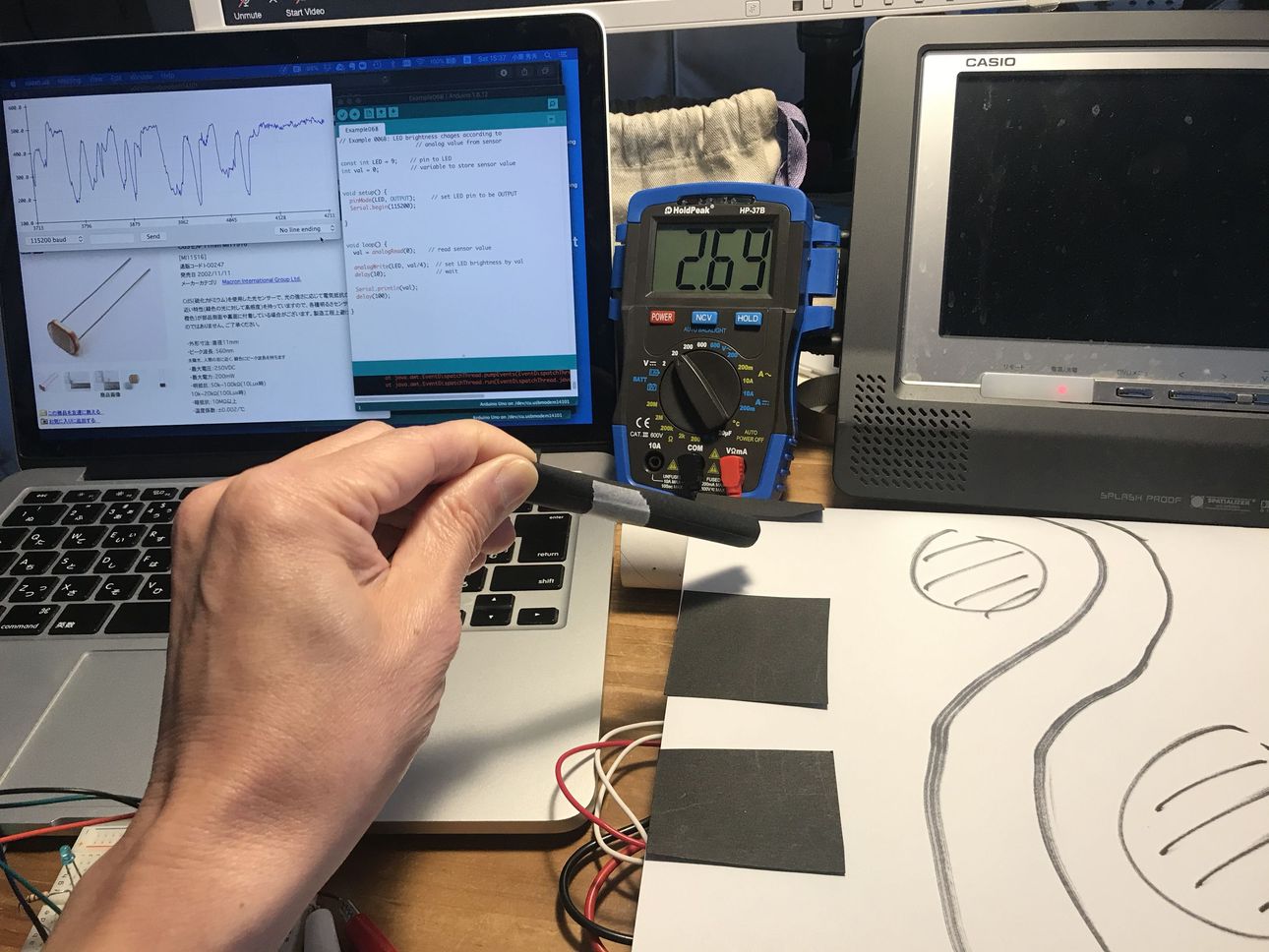
| checking the sensor voltage | cover the sensor |
|---|---|
 |
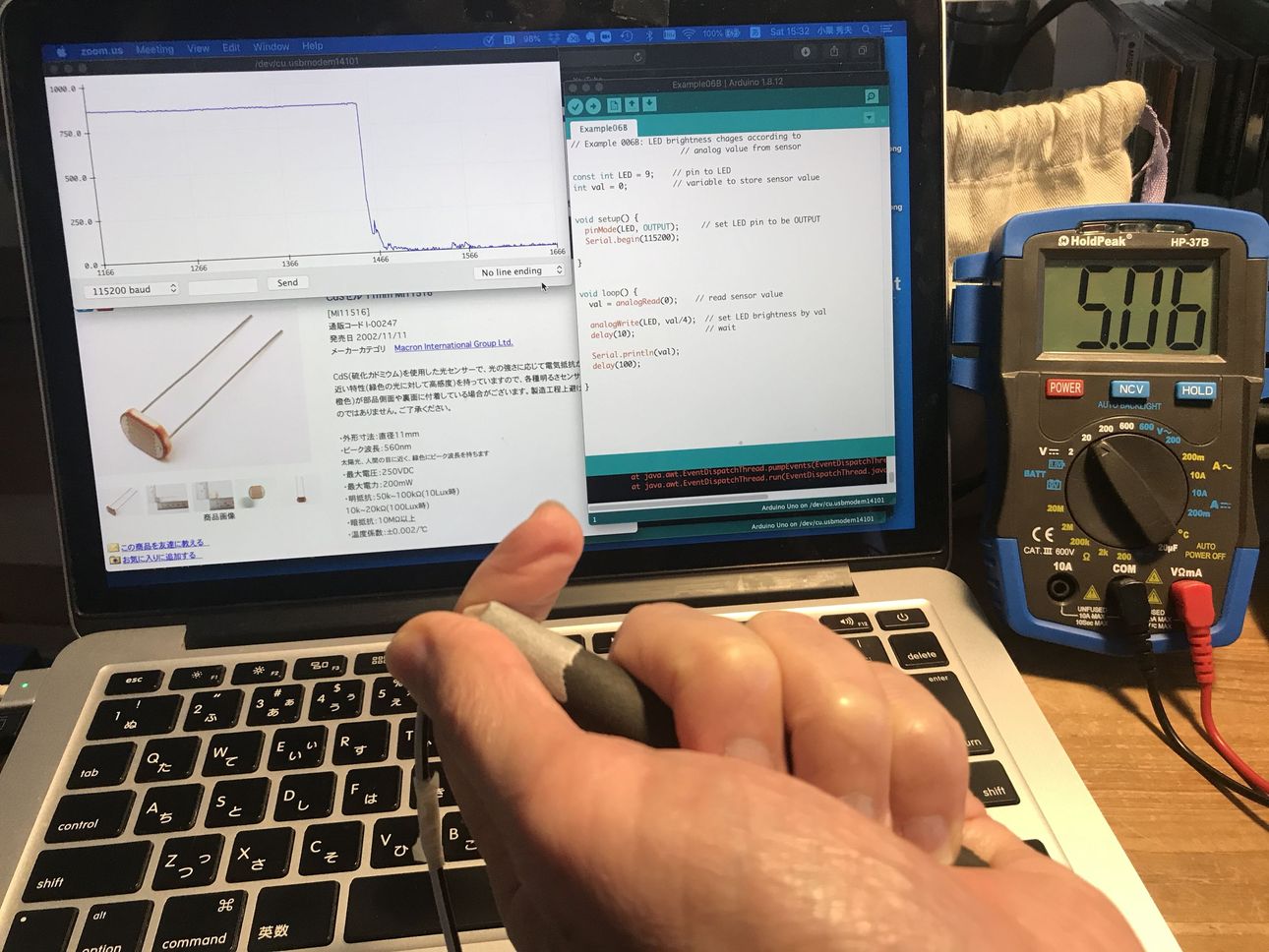 |
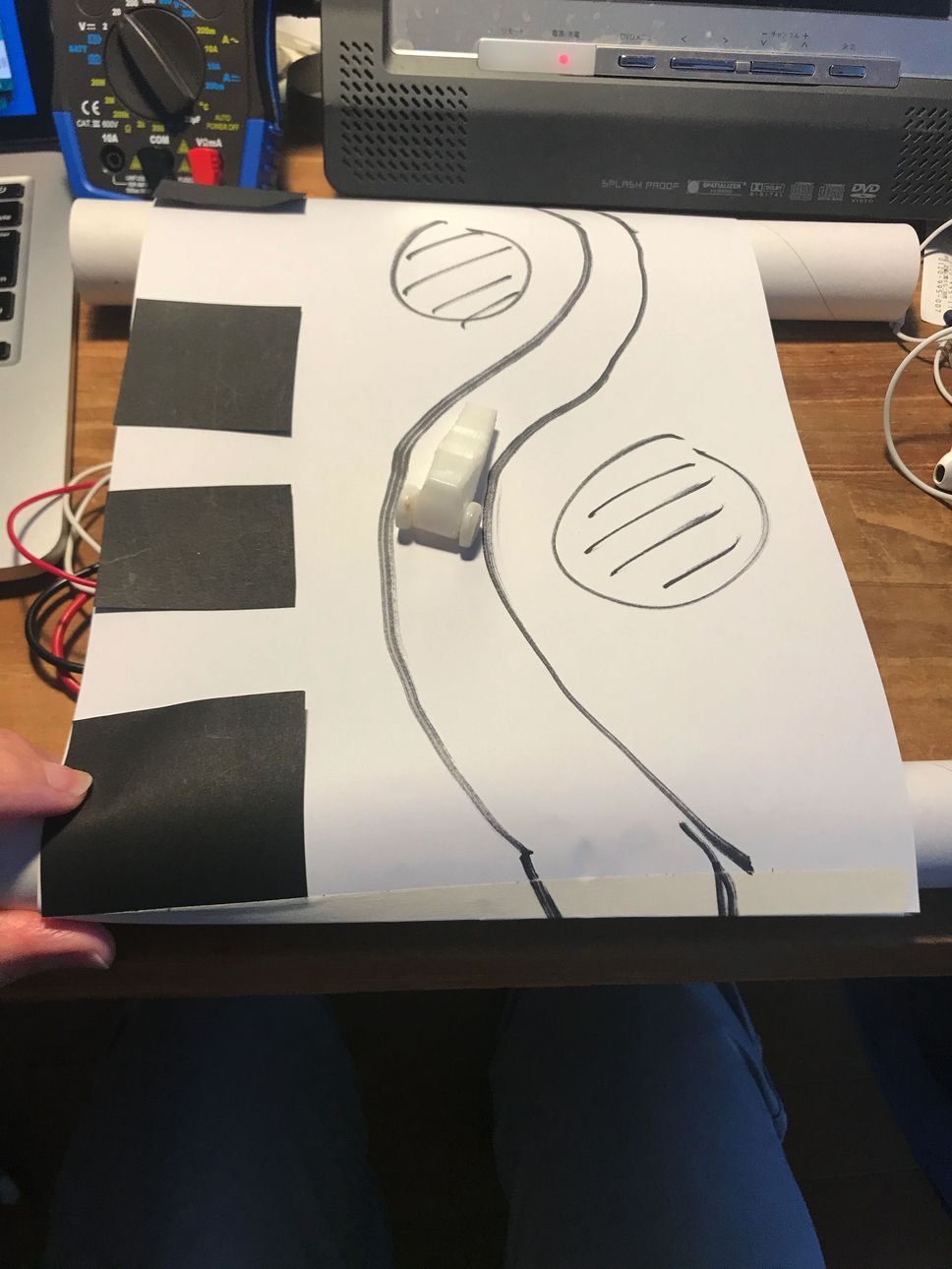
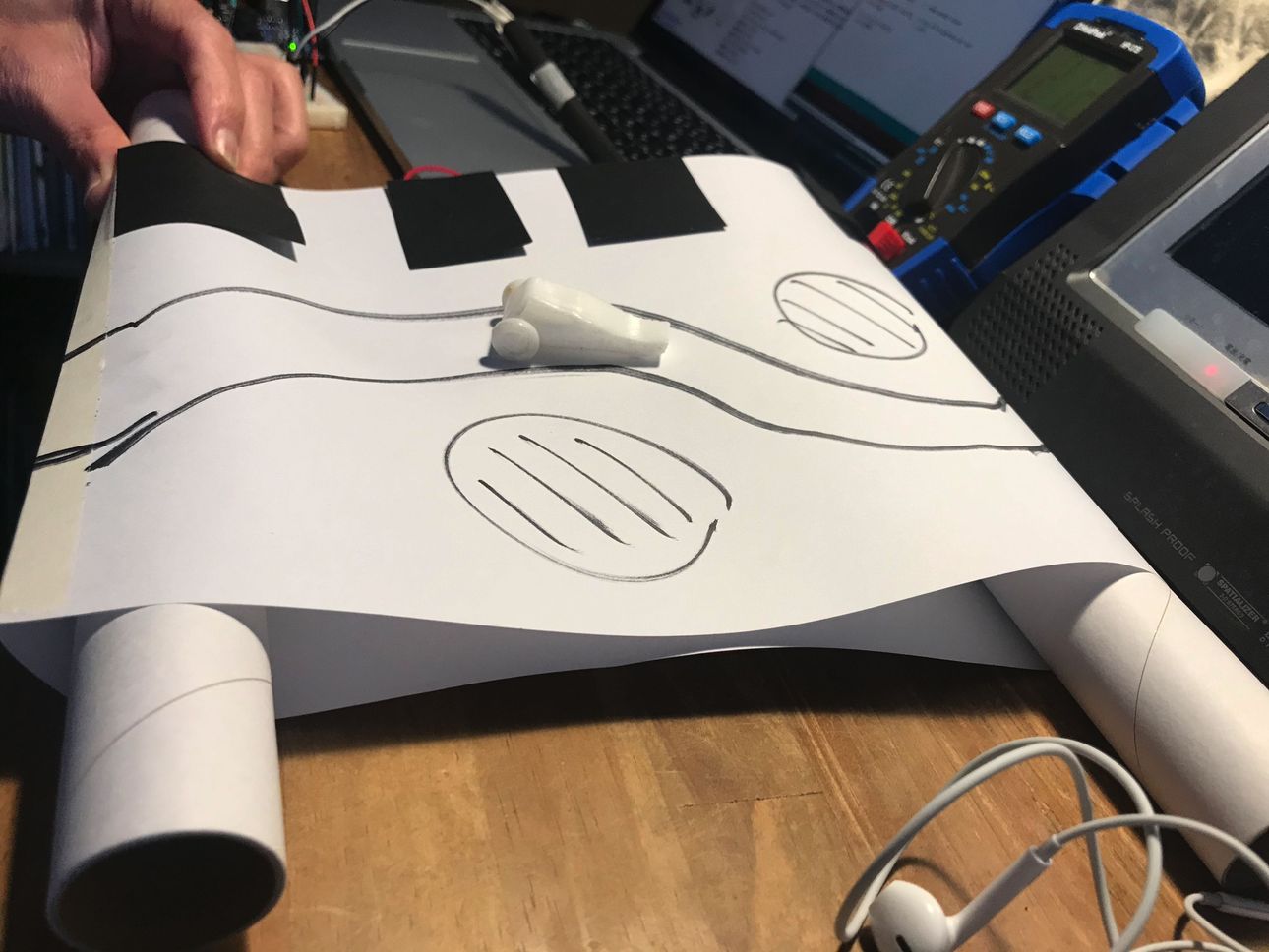
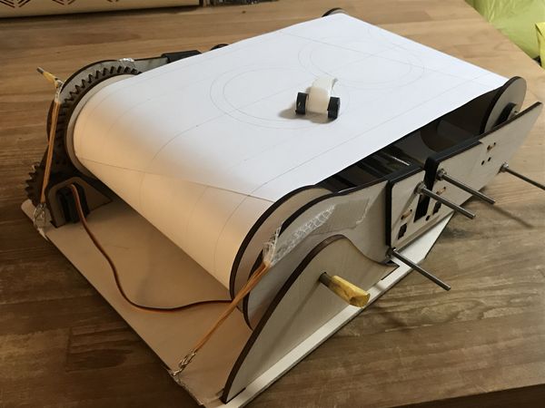
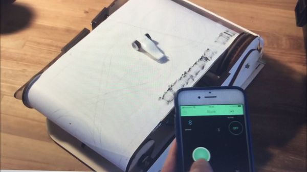
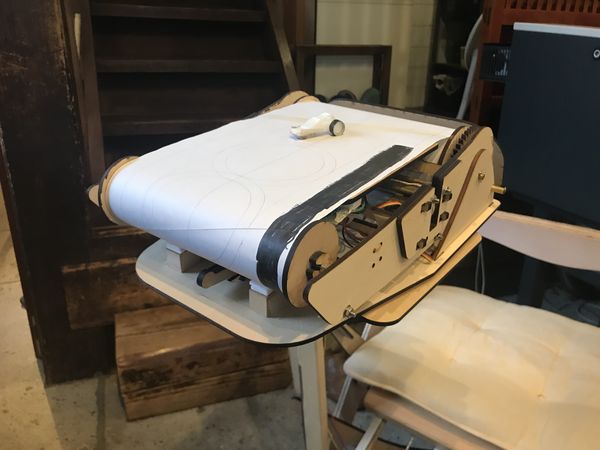
drive simulator paper course + 3d-printed car
 |
 |
Drive simulator testing
 |
 |
 |
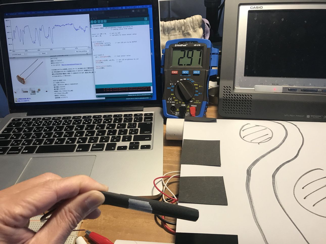 |
After this, I decided to use “photo reflector”, which is a combination of photoTR and LED, because of its fast and stable response.
Wk10 (2020/04/01) “Applications & Implications” ( detail Planning of Final Project )
Project summary, as of this week
Who’s done what beforehand?
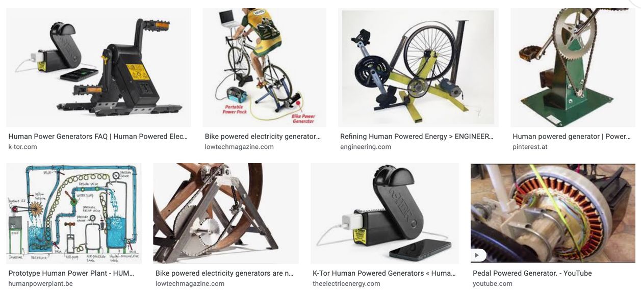
Many people made bicycle type ( or pedal & crank ) generator, but they are not suitable for the indoor use because they are heavy and bulky.
Also, there are many kinds of exercise machines but most of them are just wasting the energy, in other words, just converting the mechanical energy ( from human body ) to heat energy, not producing electricity.
examples of human-powered generator
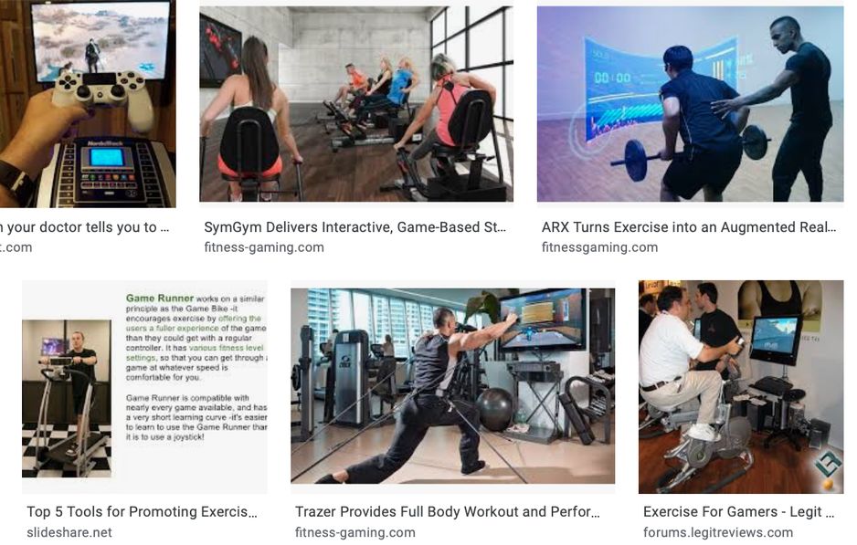
examples of gaming exercise
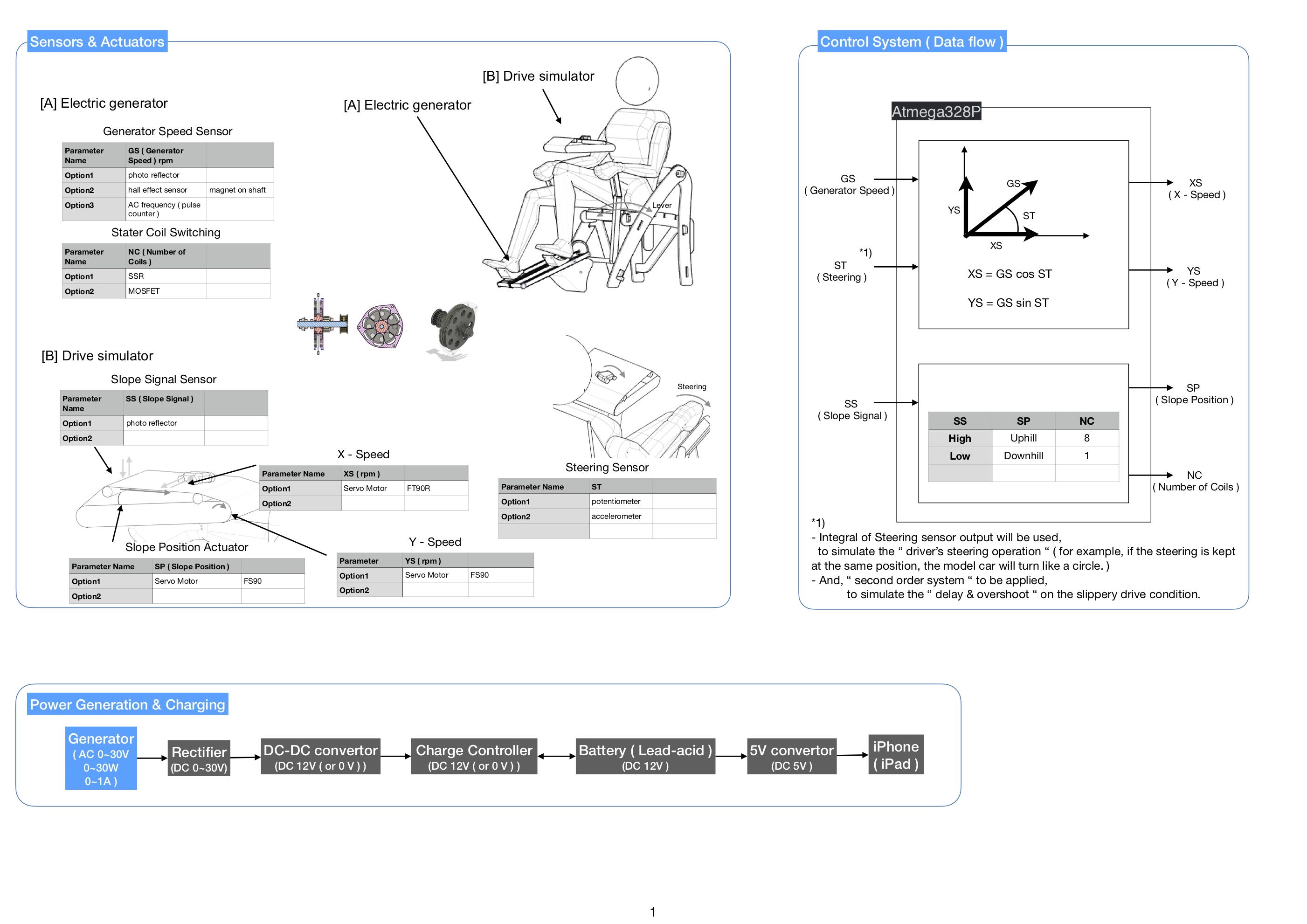
System Configuration
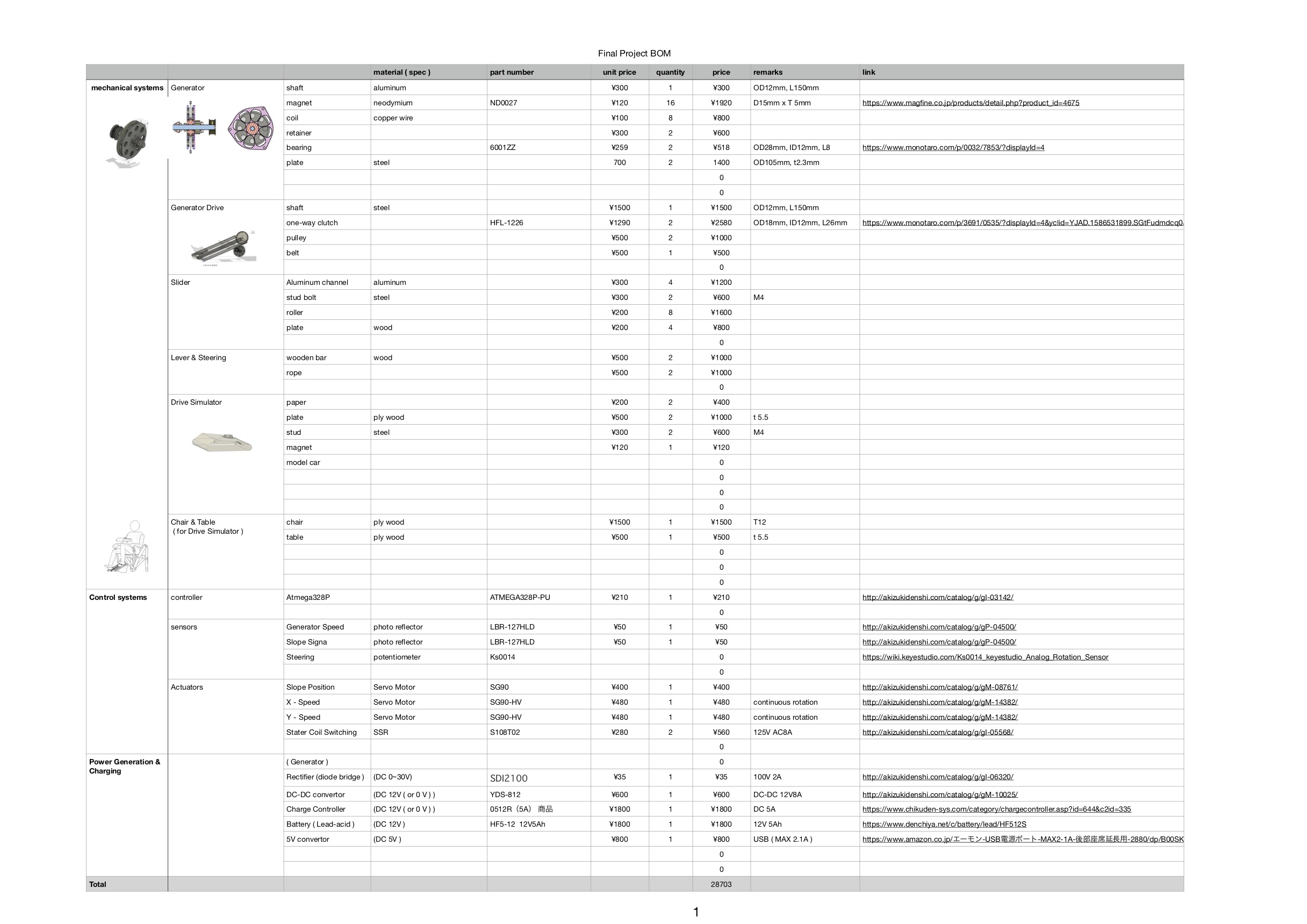
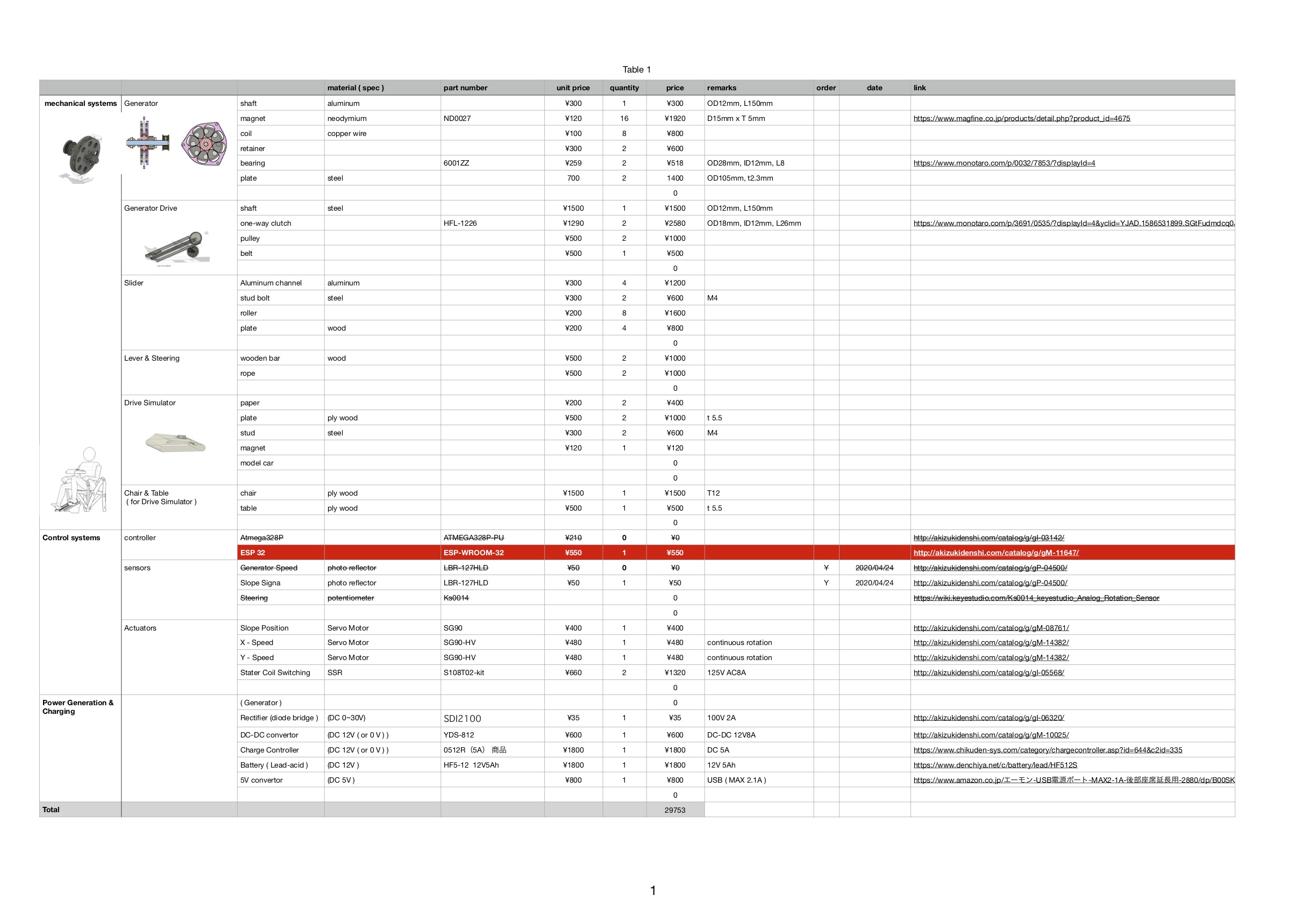
Bill of Materials
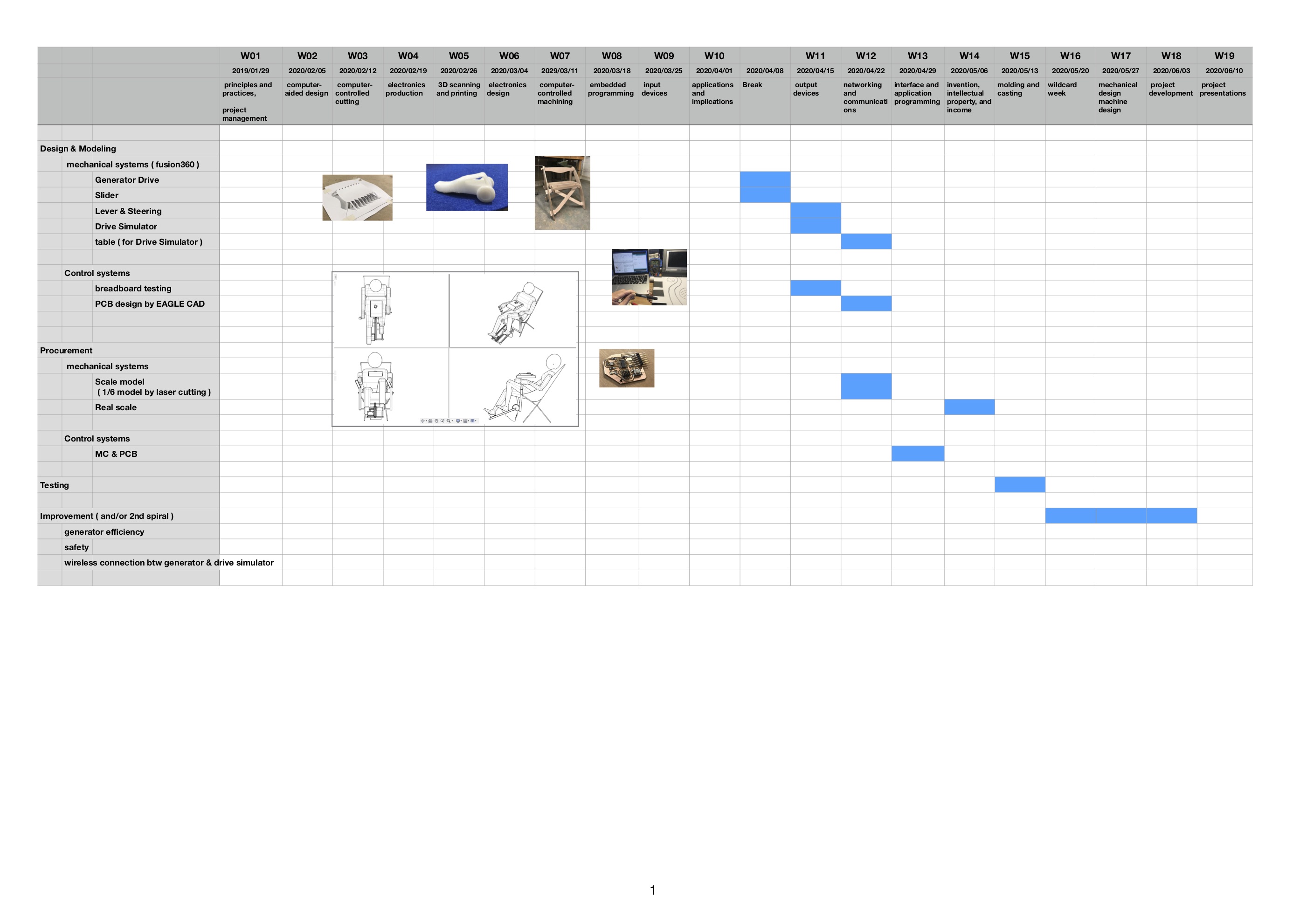
Schedule
Wk11 (2020/04/15) “Servo Motor Testing”
1) Controling the Servo Motor by ATtiny44
| test | board | input device | software | output device | software | |
|---|---|---|---|---|---|---|
| 4 | serial | ATtiny44-board-week08 | none | Processing | SG90-HV | Arduino IDE |
code, processing ” slider_serial_test.pde “
code, Arduino ” servo_Dimmer_test_ATtiny44.ino “
Wk13 (2020/04/29) “Drive simulator, functional mockup”
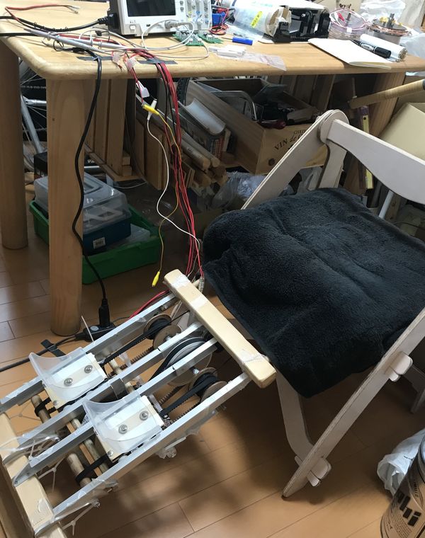
Wk14 (2020/05/06) “Generator system, mockup”
 |
 |
Wk18 (2020/06/03) Project development (Reviewing the Final Project Status)
Please refer “W18 - Project development”, for the detail of this week.
1) what tasks have been completed, and what tasks remain?
completed
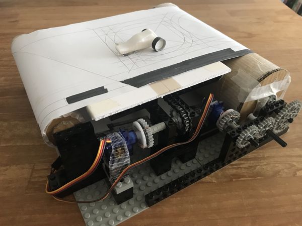
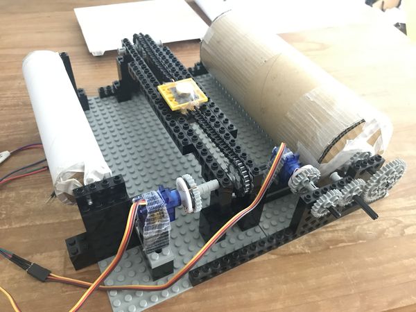
functional prototyping of the items below
leg powered Generator and Drive simulator ( LEGO components )
 |
 |
 |
 |
remaining items
design the laser cut version of Generator and Drive simulator [ item A ]
better packaging including the wiring [ item B ]
charging DC 12V battery system
hand powered item
wireless communication between generator control and simulator control
haptic factor of the Drive simulator
2) what’s working? what’s not?
Generator works, but the output power is low ( about 5 watt )
Drive simulator works, but the Steering control with potentiometer is not easy.
3) what questions need to be resolved?
How to get more generator output?
To charge smart phones, at least 15 W is required, considering the power loss due to the charge/discharge efficiency of 12V battery and the power consumption of Drive simulator.
The bottle neck limiting the generator output so far is the slippage of the generator belt system.
Therefore, more robust design of the slider and belt system is needed. [ item C ]
How to improve the Steering system of Drive simulator?
Instead of using wired potentiometer, try wireless system like BLE.
To do this, I’ll change the MCU from Atmega328P to ESP32, so that I can try wifi/BLE. [ item D ]
4) what will happen when?
I’ll complete the above [ item A, B, C, D ] by the end of June, so that I can be ready for the Final Project Presentation in Mid July.
5) what have you learned?
a lot, especially,,, electronics production, IoT basic
ability to solve the problems which I’m not familiar with
Updated System Configuration
Updated Bill of Materials
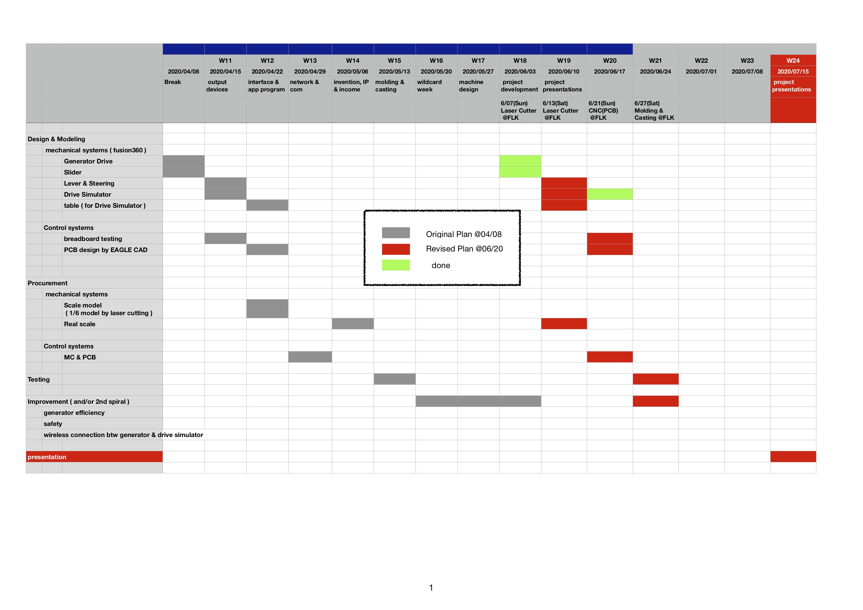
Updated Schedule
Wk19 (2020/06/10) “Making Generator”
 |
 |
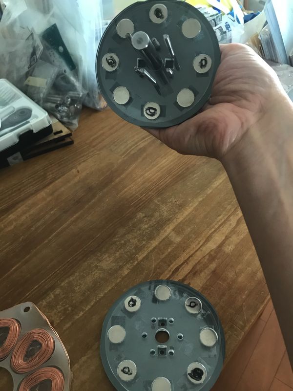
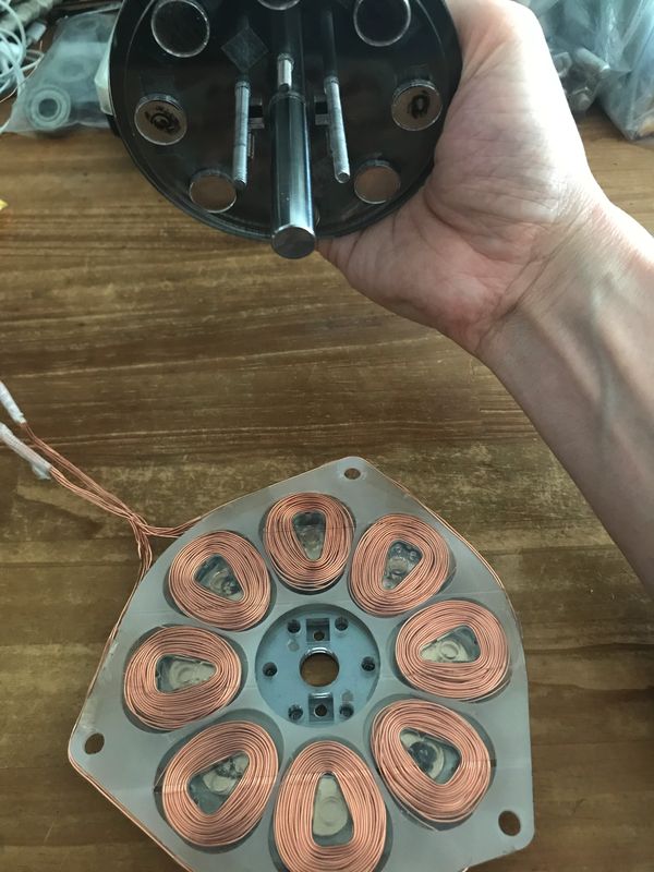
1) Coil and Stator
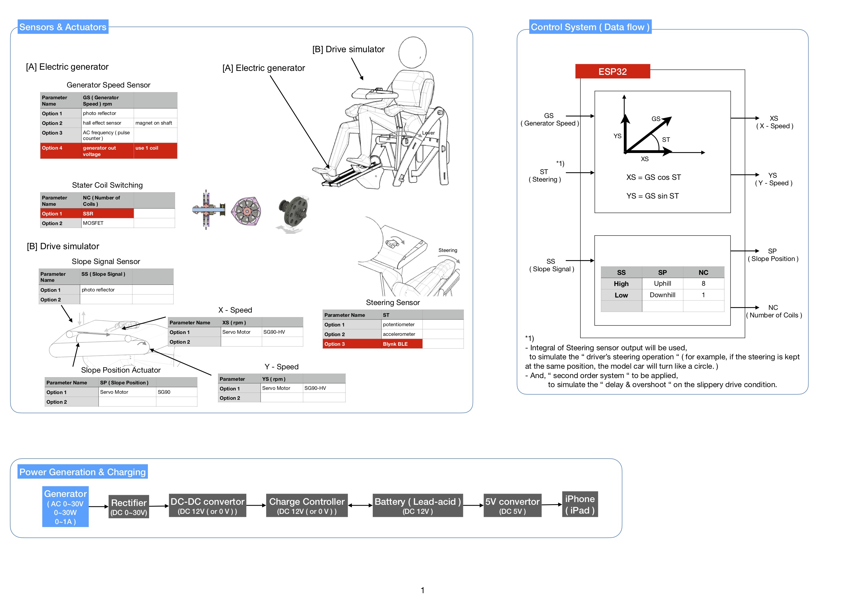
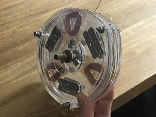
I designed an “axial flux generator”, which has 8 coils, 105mm outer-diameter rotor with 16 Neodymium magnets. This generator is supposed to produce single-phase alternative current. Basically, the coils are connected as series, but the number of working coil can be switched by using SSR (solid-state Relay) from the controller.
| shaft, bearing, pulley | rotor, stater |
|---|---|
|
|
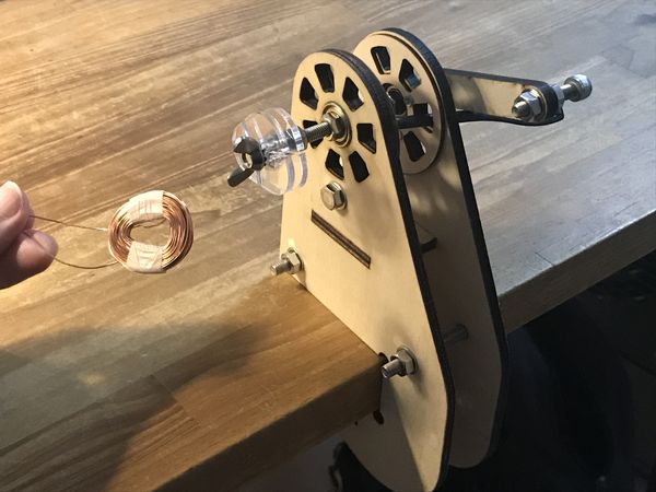
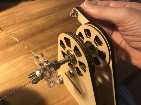
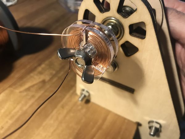
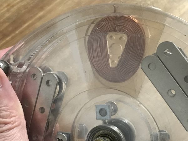
I used the Coil winder which I designed about 2 years ago.
 |
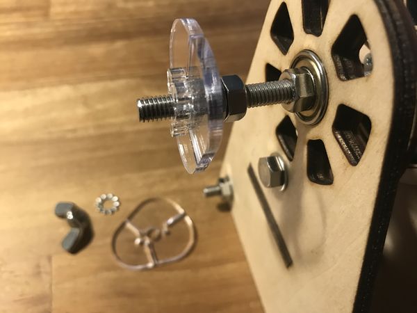 |
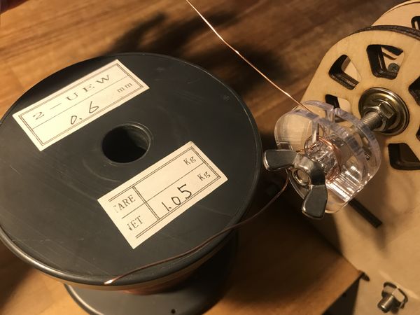
| 0.6 mm Wire | 90 turns |
|---|---|
 |
 |
 |
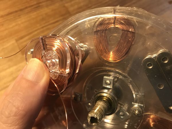 |
( These photos and video are the example of functional testing with the 3-coil transparent generator. )
 |
 |
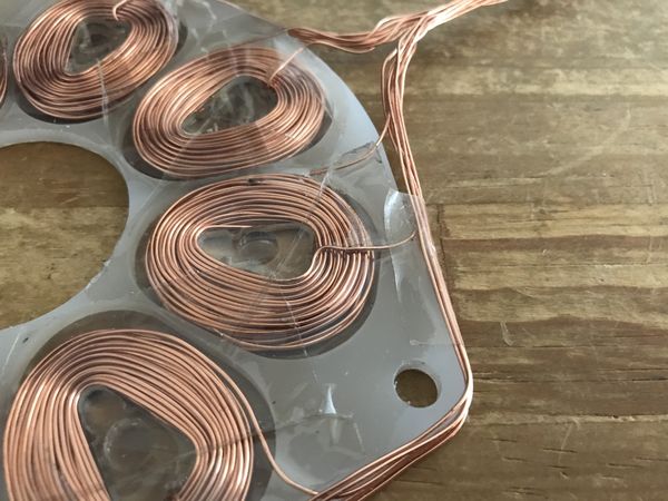
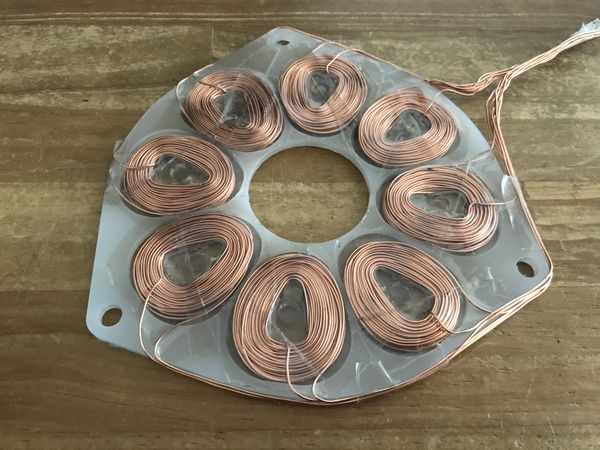
Fixing the coils by using Teflon tape on the stater ( laser-cut acrylic plate ).
 |
 |
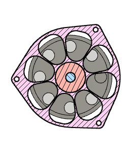
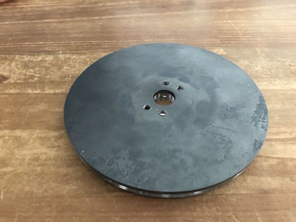
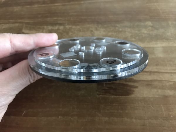
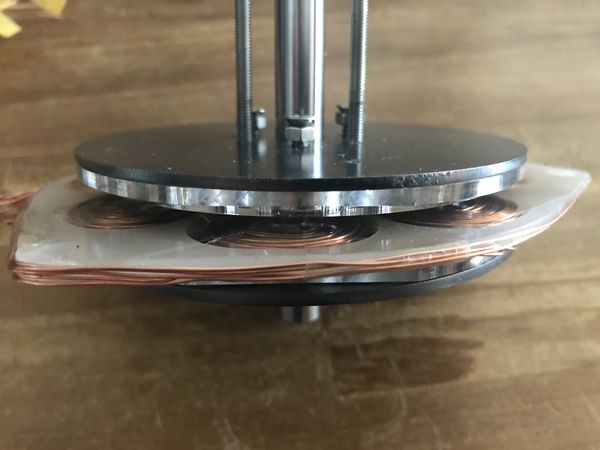
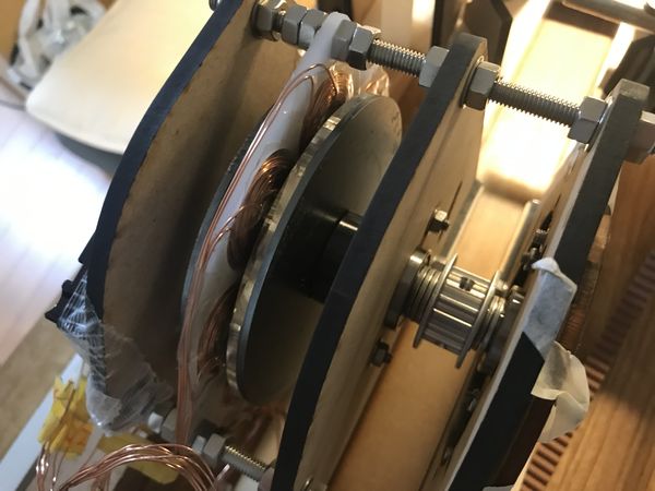
2) Rotor ( magnet plate ), Generator Assembly
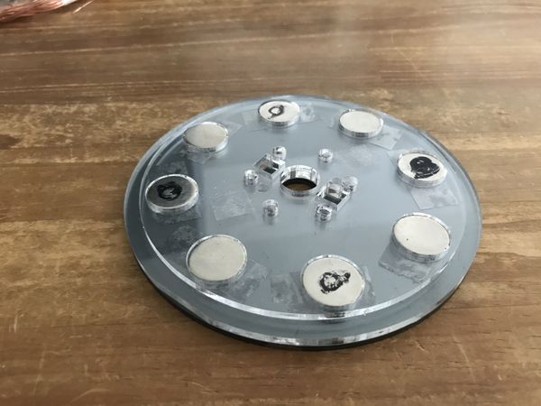
The Rotor is the combination of magnets, steel plate and acrylic plates ( for magnet positioning purpose ).
As I didn’t have an access to a high power laser cutter, steel plate cutting were outsourced.
 |
 |
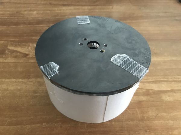
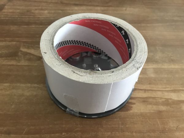
Handling of powerful magnets are a kind of dangerous. It should be done carefully, and as soon as they have been attached to the steel plate, the plate should be covered by something which has enough thickness ( length ) to avoid any accidents.
 |
 |
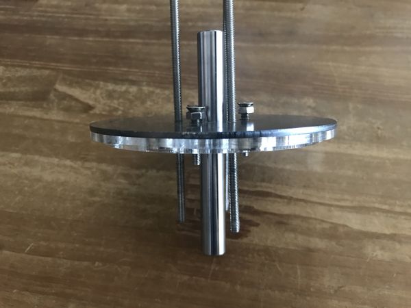
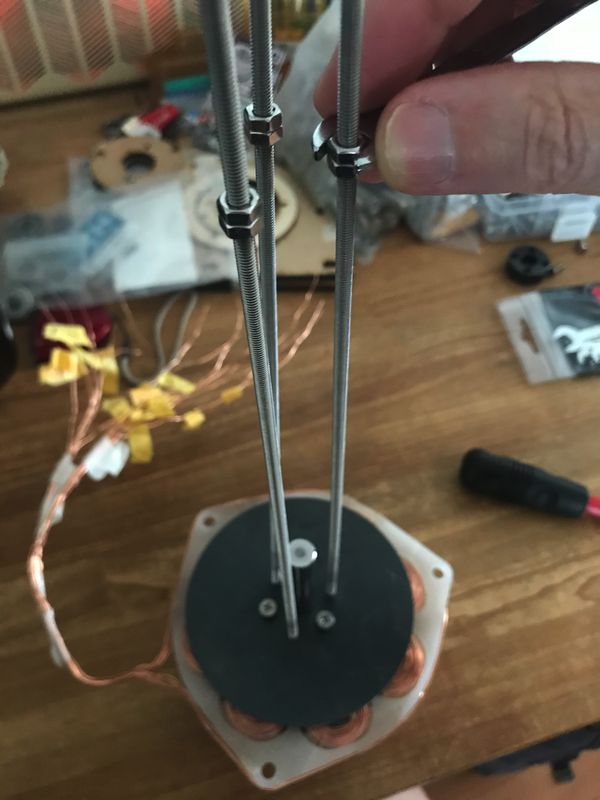
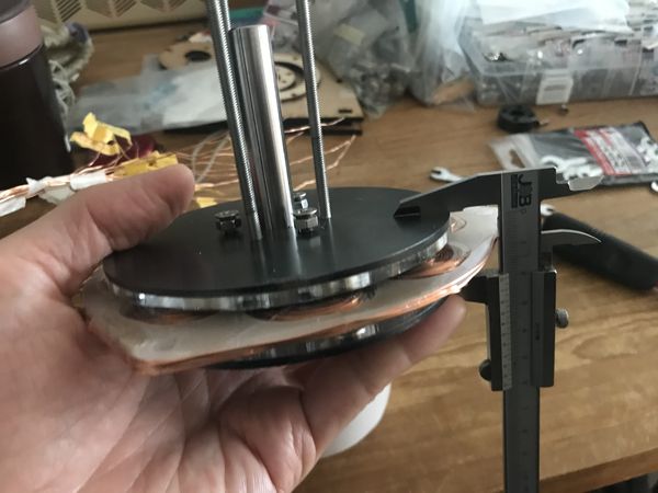
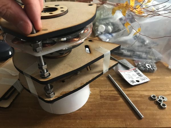
In order to assemble the rotor plates and stater plate, set 3 short bolts and 3 long (stud) bolts. ( Screw them into the female thread holes on the steel plate. )
 |
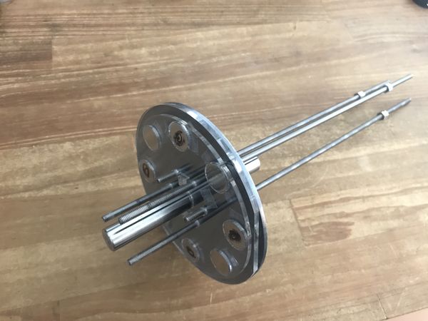 |
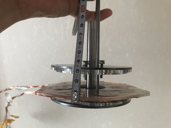
set the long stud bolts about 70 mm protruding from the steel plate.
 |
 |
 |
 |
Turn the long bolt so that the steel plate gradually approaches to the other.
 |
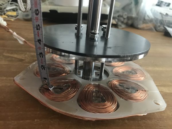 |
In this case, when the clearance between 2 steel plates became about 35 mm, the magnetic power could hold the lower steel plate.
 |
 |
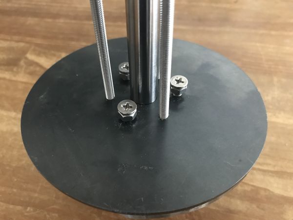
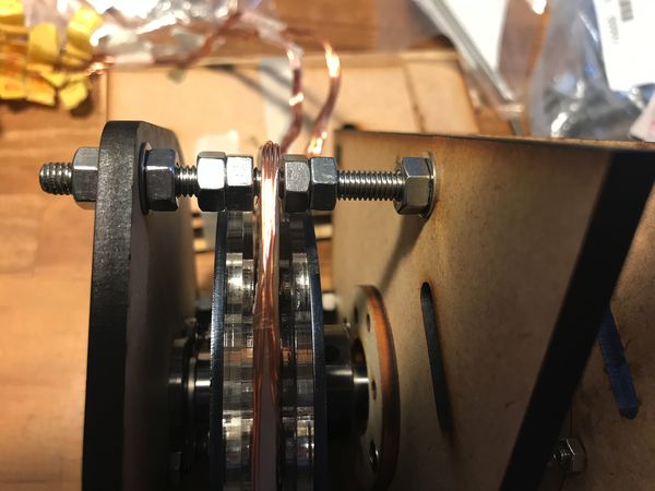
After the 2 steel plates have been set close enough to be supported by short 3 bolts, remove the 3 long stud bolts.
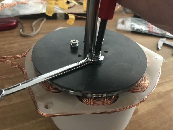
Then, checking the parallelism of 2 steel plates, adjust the 3 short bolts, so that the clearance between the magnets and the coils on stater plate could be minimized.
 |
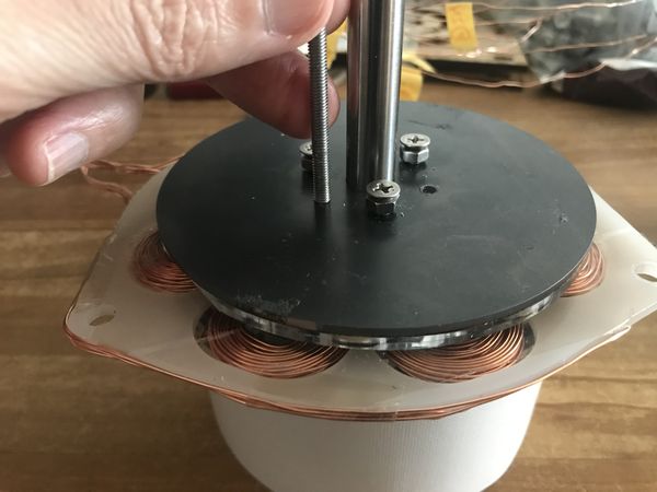 |
Tighten the nuts on the short bolts, to avoid self-loosening.
 |
 |
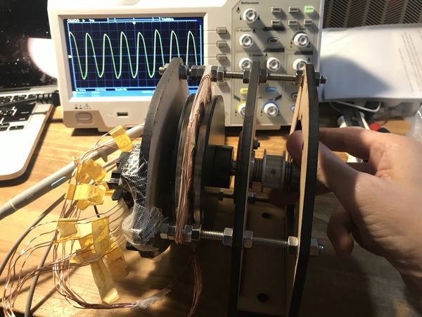
Assemble the generator housing plates, which support the stater plate and shaft bearings.
Then, alternative current was observed by oscilloscope.
 |
 |
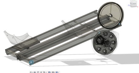
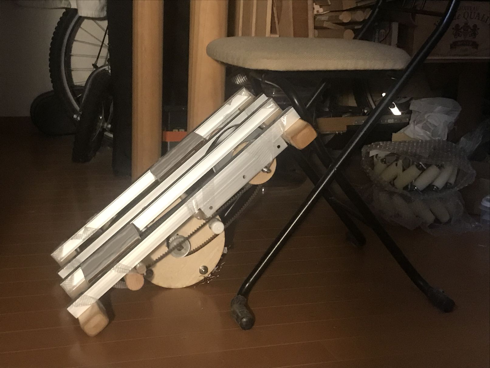
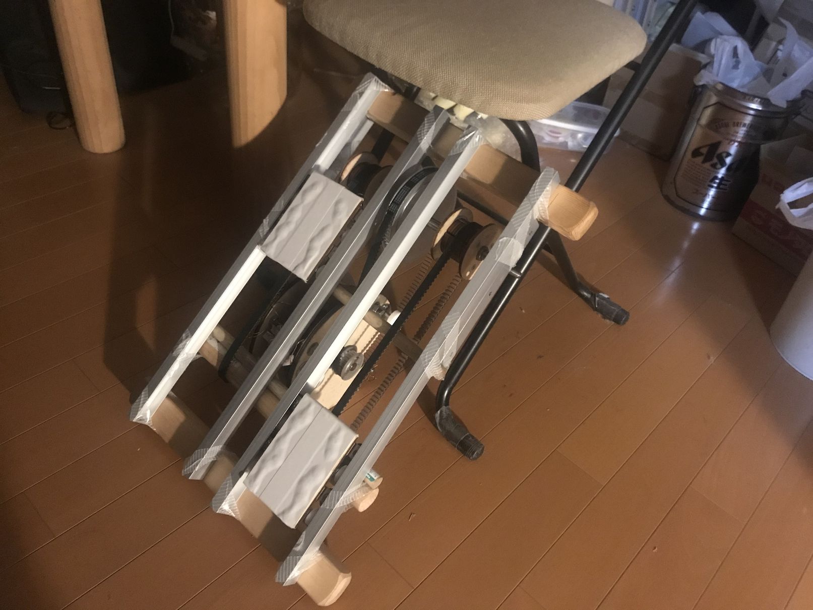
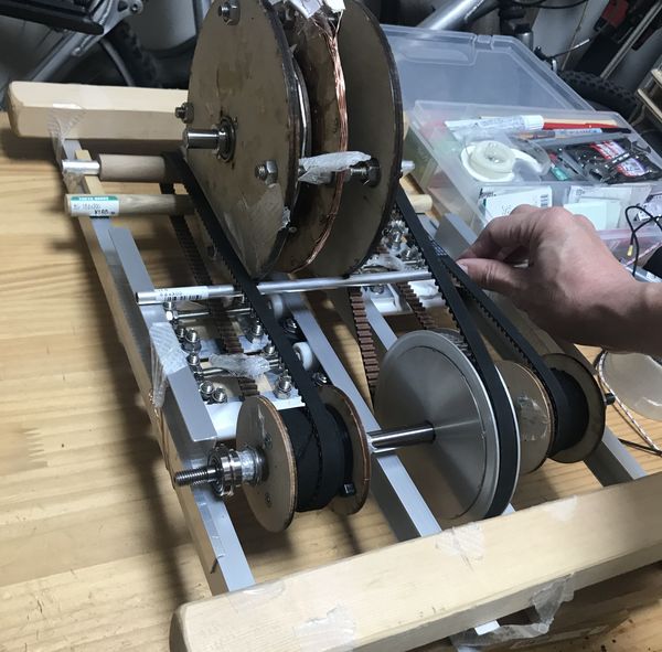
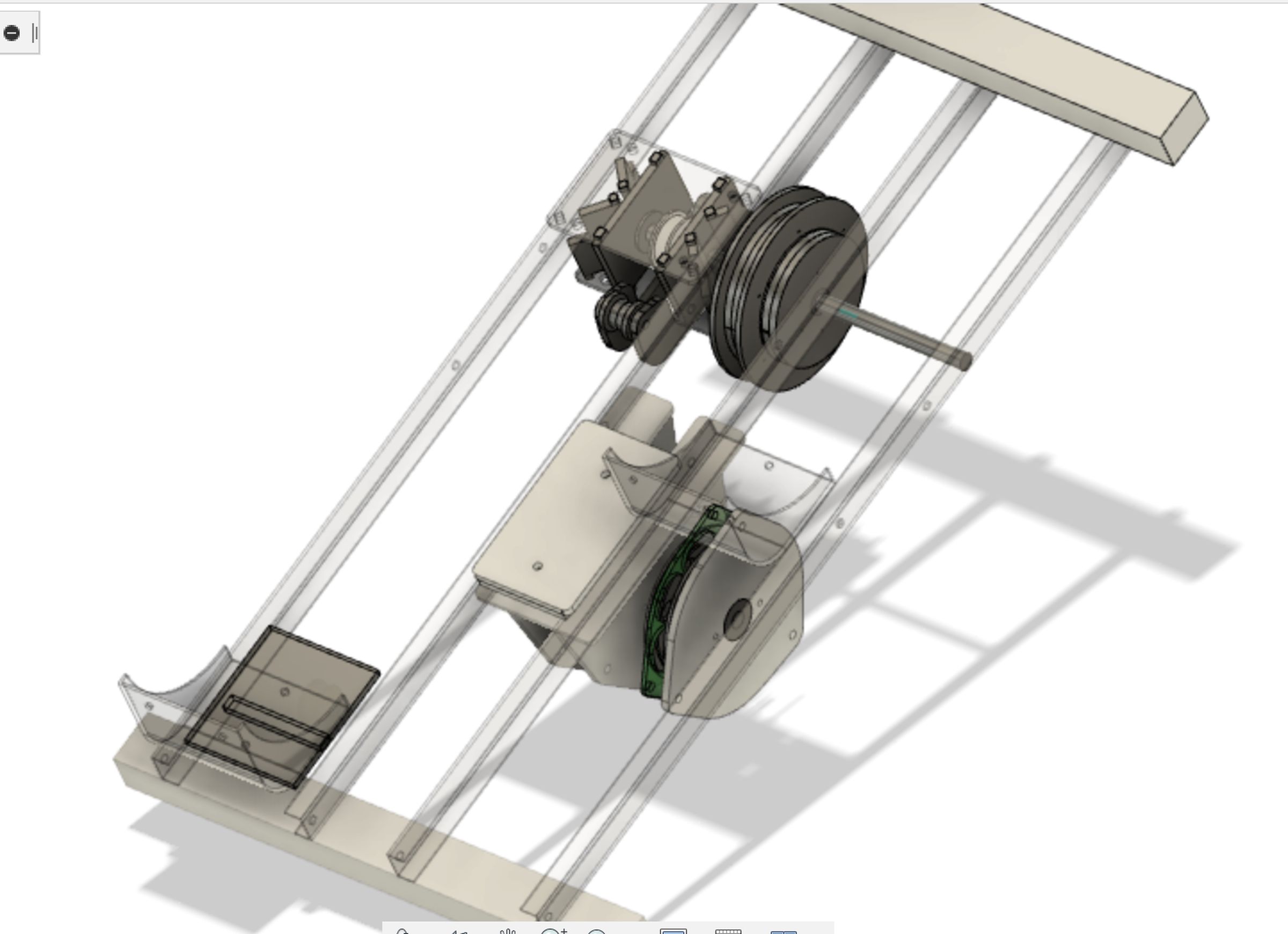
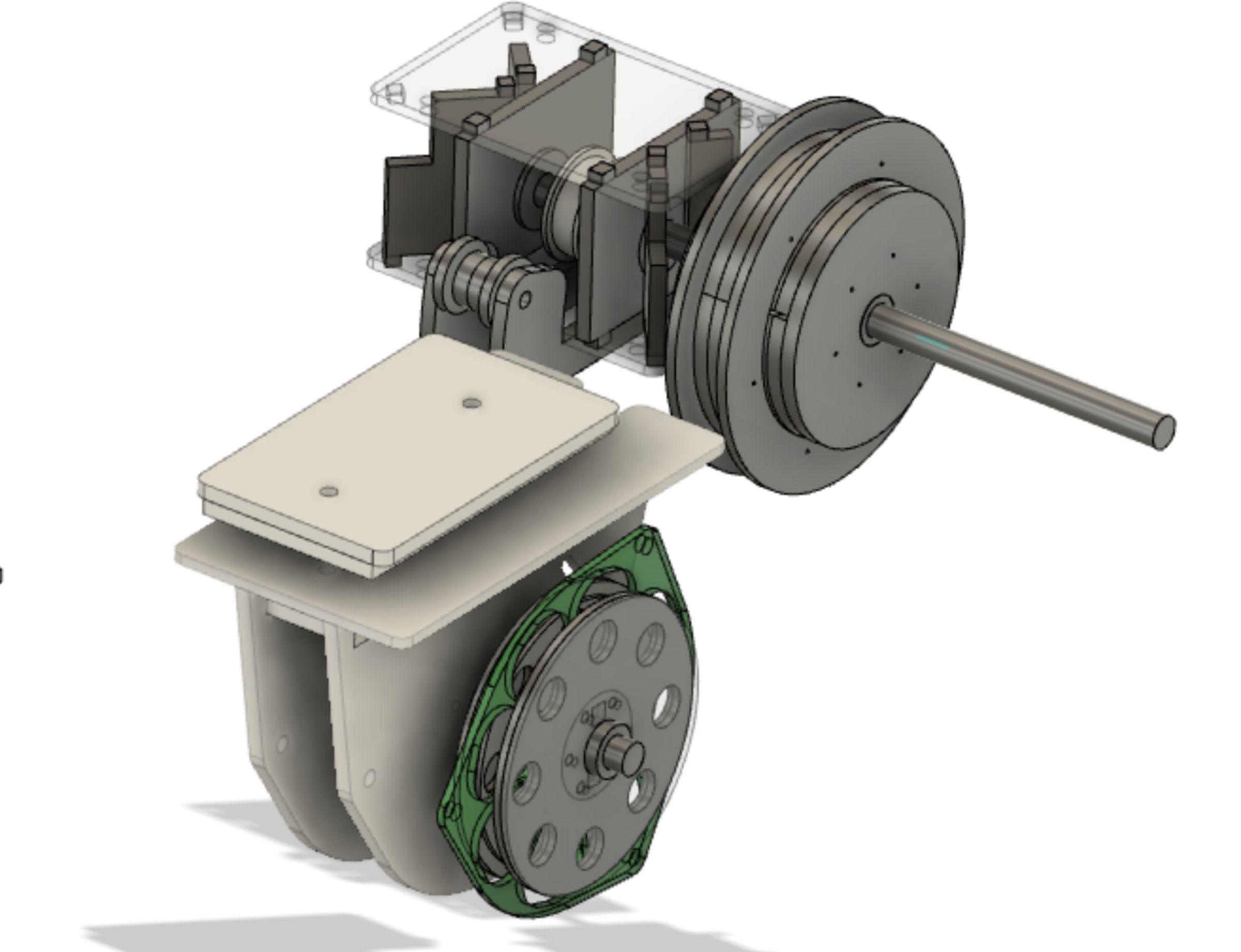
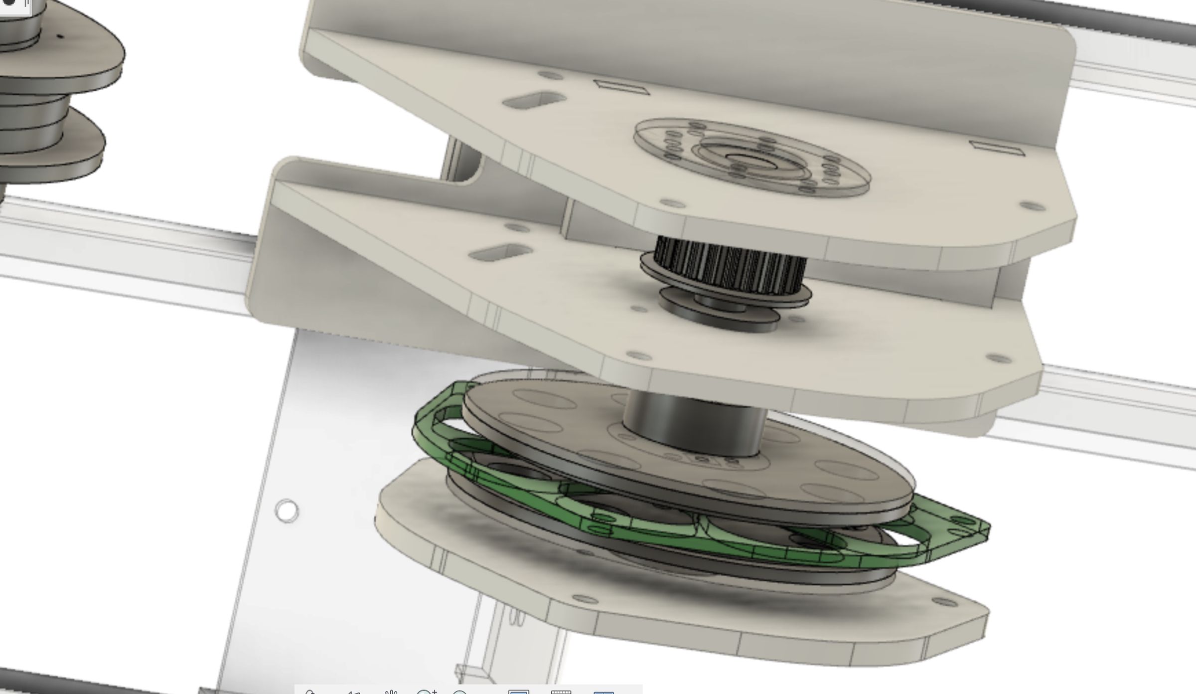
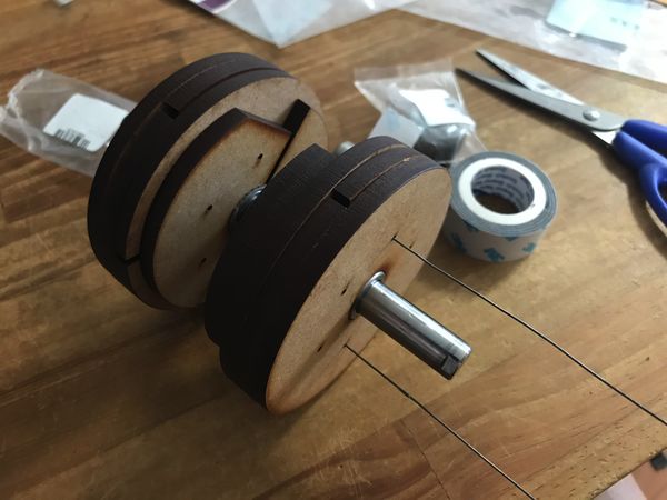
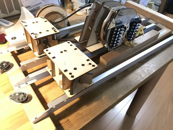
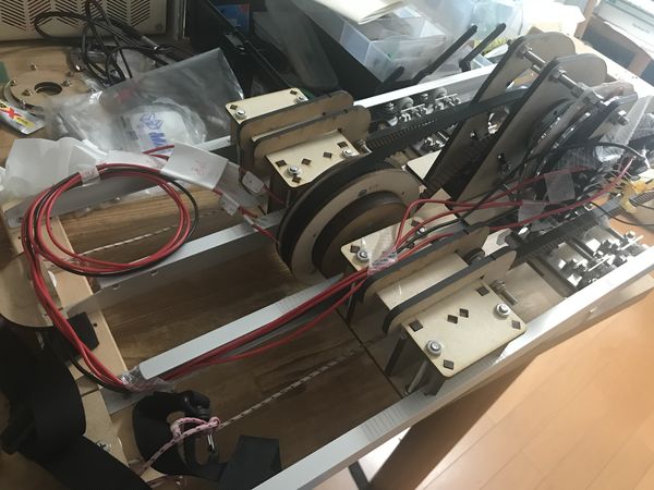
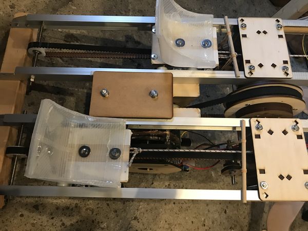
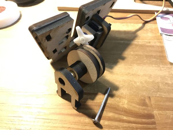
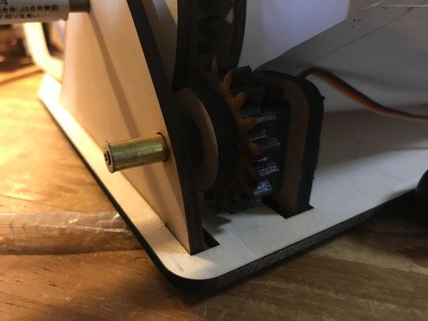
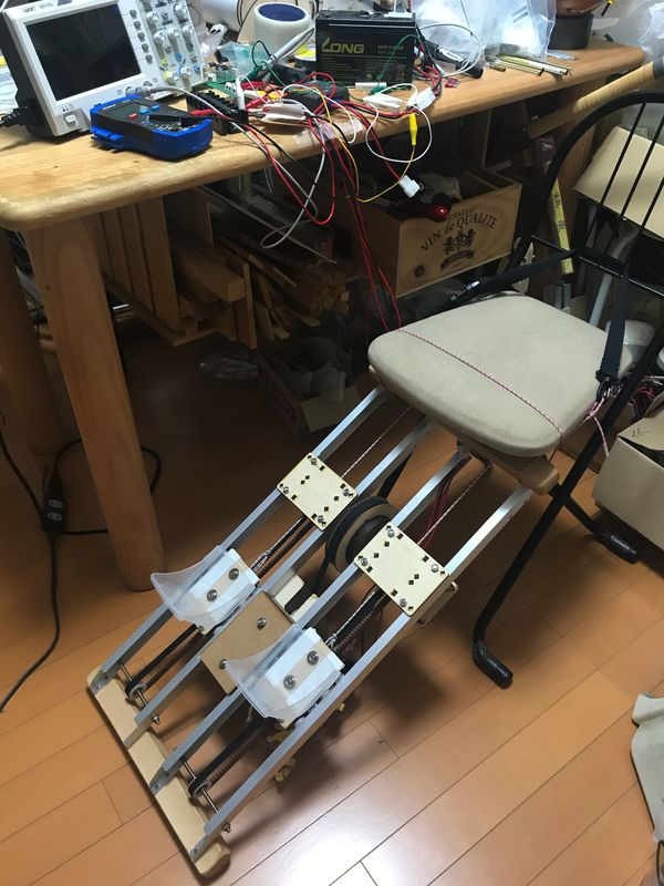
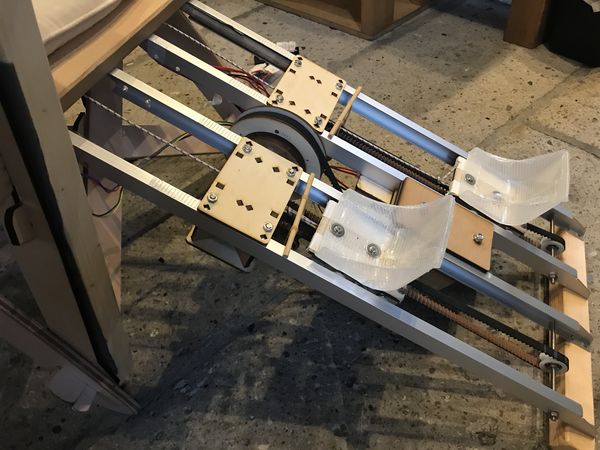
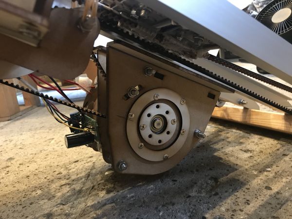
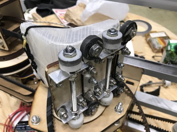
3) Generator Drive System ( Slider )
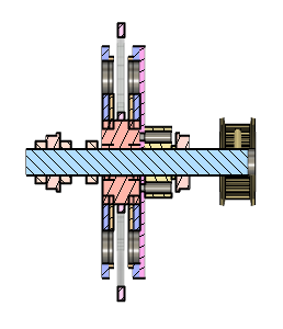
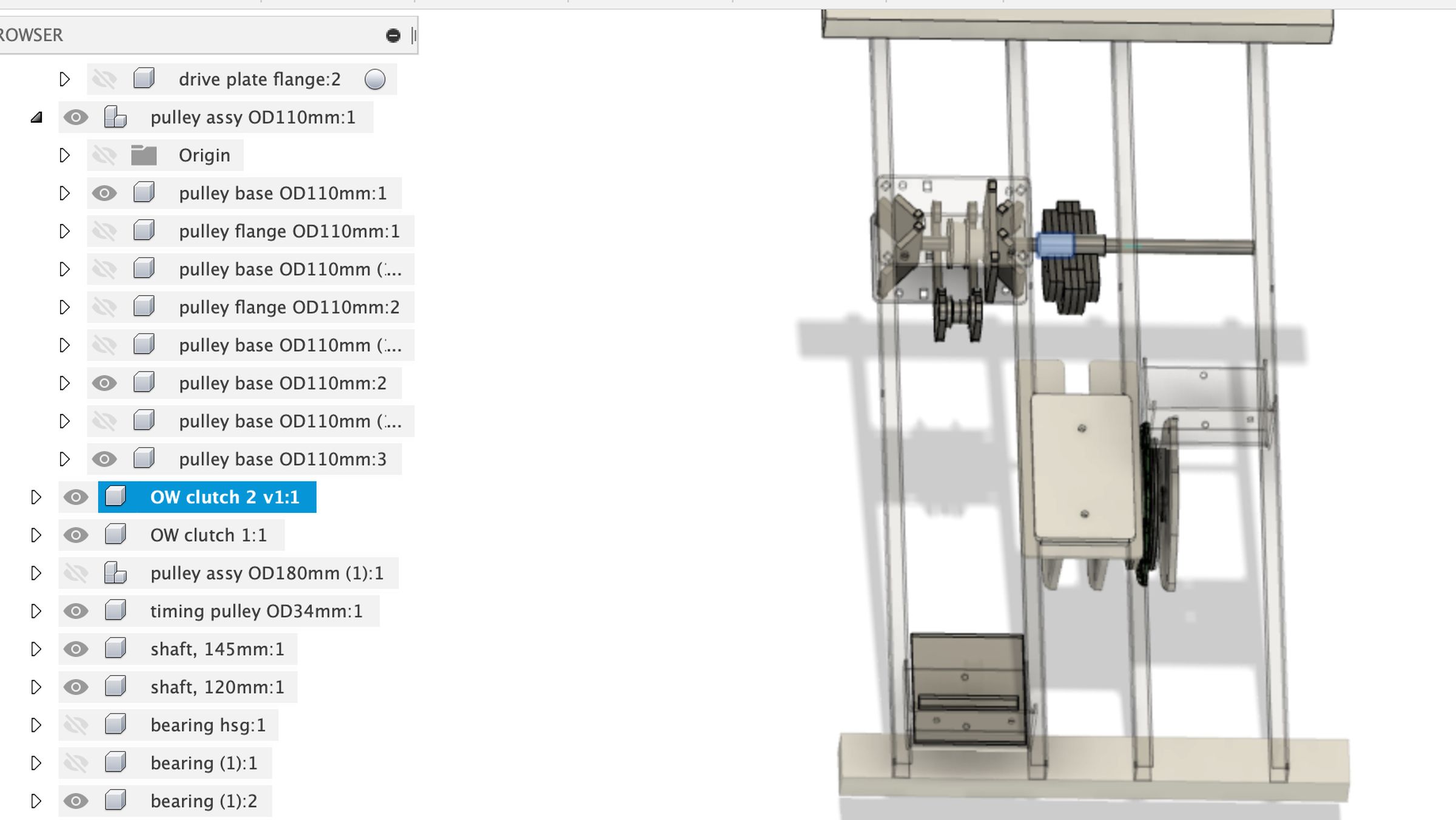
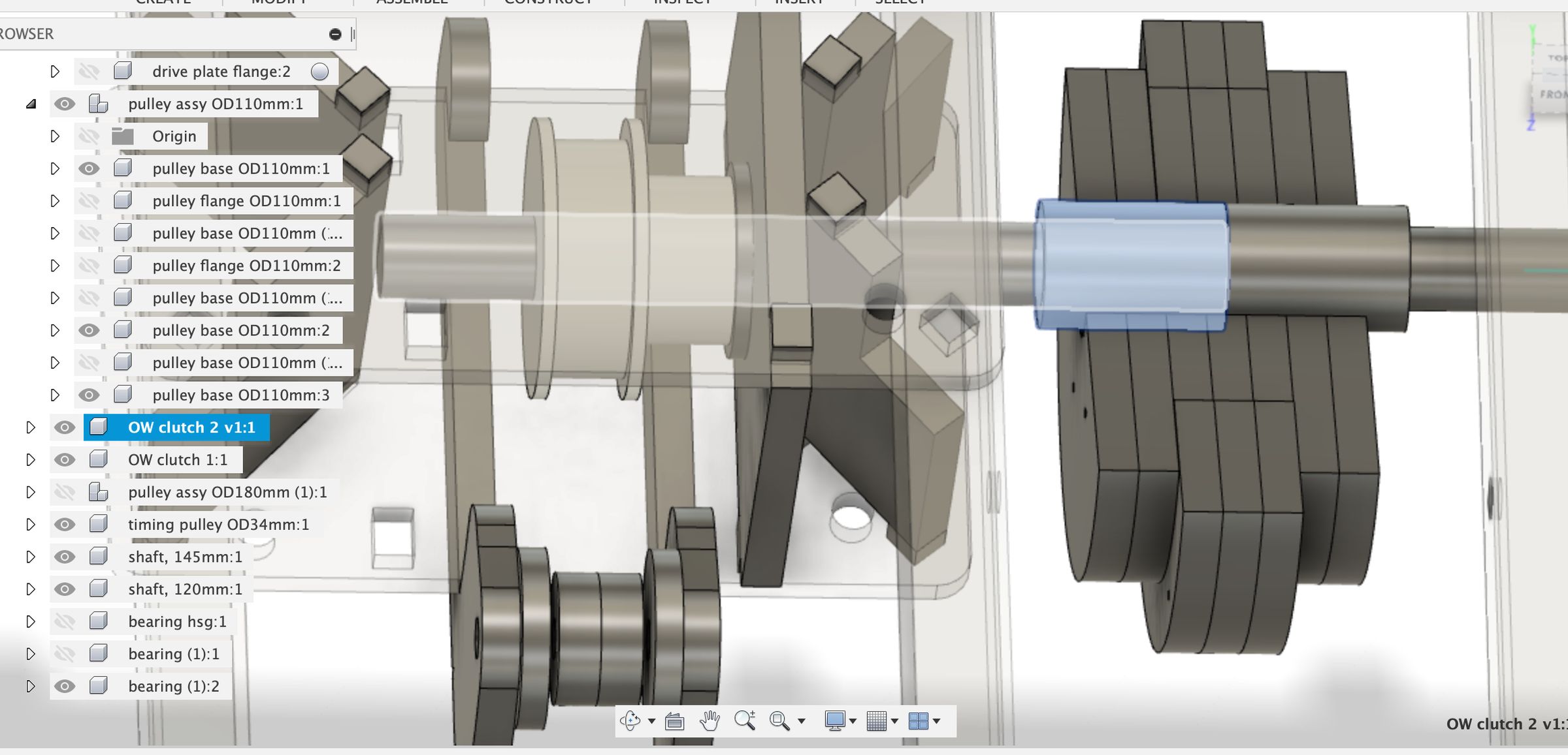
Drive pulley (left large pulley in the figure below) is supported by 2 shafts ( Right-leg side & Left-leg side).
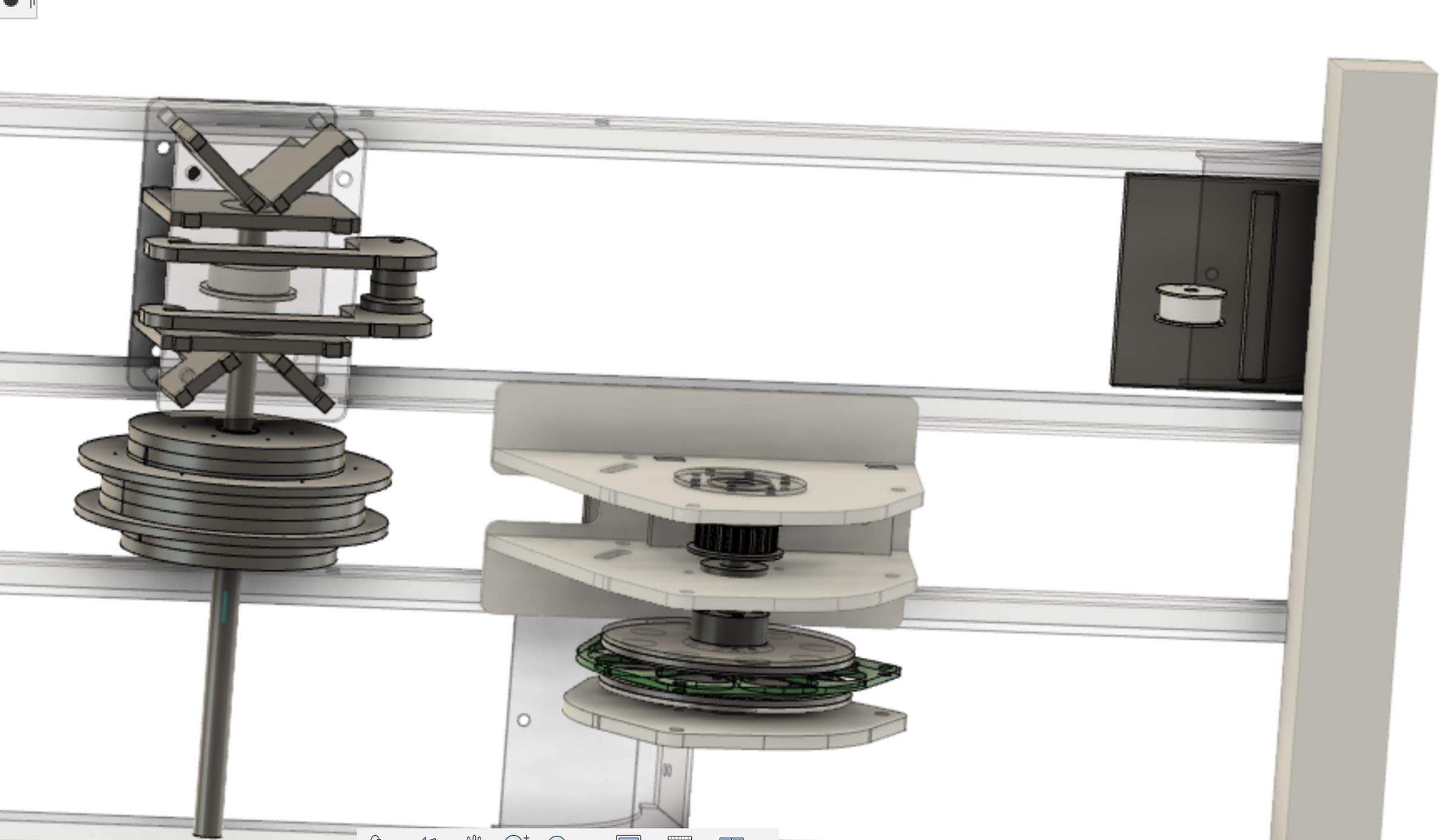
The Drive pulley contains 2 one-way clutches which are connected to Right-shaft and Left-shaft respectively, so that the reciprocating motion of the both legs can rotate the Drive pulley alternatively.
| One-way clutch for right-shaft is highlighted. | One-way clutch & right-shaft are highlighted. |
|---|---|
 |
 |
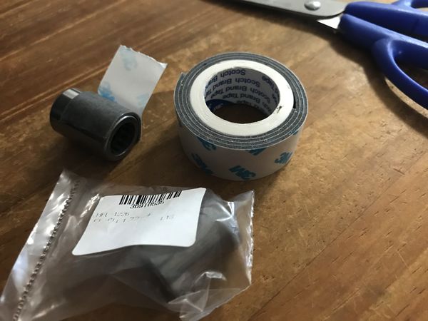
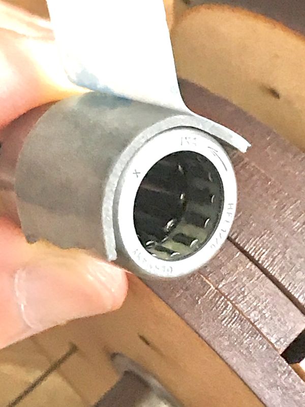
Assembling the Drive pulley
| double-sided tape for the torque transmission from one-way clutch to Drive pulley | |
|---|---|
 |
 |
| core of the Drive pulley | |
|---|---|
 |
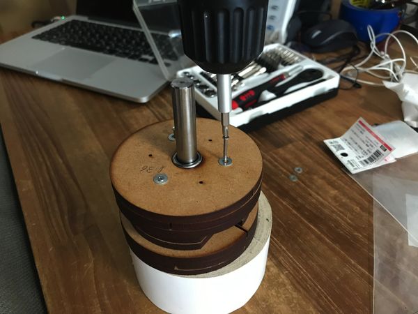 |
 |
 |
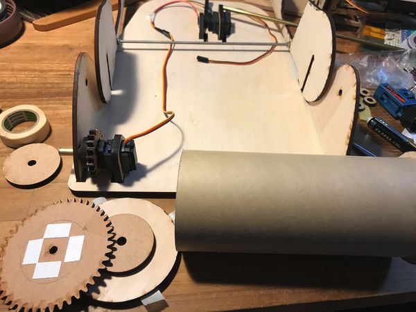
| timing belt for Drive pulley and Generator pulley | timing belt for the sliders ( pedals ) |
|---|---|
 |
 |
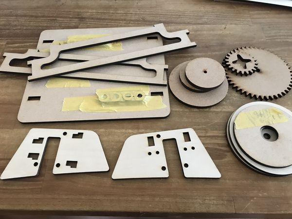
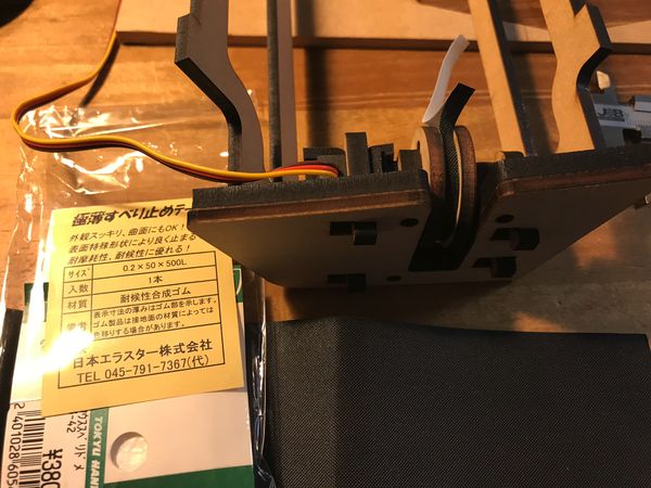
For the cost reduction, Drive pulley is made of laser-cut wooden plate, and rubber-sponge was pasted on it, to avoid slippage of the belt.
Wk20 (2020/06/17) “detailed 3D modelig”
Generator, Drive simulator, CNC chair
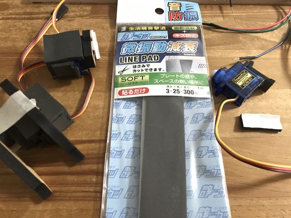
Wk21 (2020/06/24) “Laser Cutting, Drive-simulator, etc”
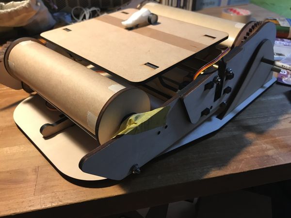
Assembling the drive simulator
| laser cutting parts | put rubber sheet on servo motor, for noise reduction |
|---|---|
 |
 |
| output 2 ; servo motor for magnet control ( SG90-HG (continuous rotation)) | |
|---|---|
 |
 |
| output 3 ; servo motor for slope control ( SG90 (lever-motion)) ( in the back of this photo ) |
output 1 ; servo motor for rolled paper control ( SG90-HG (continuous rotation)) |
|---|---|
 |
 |
 |
 |
Wk22 (2020/07/01) “Control System”
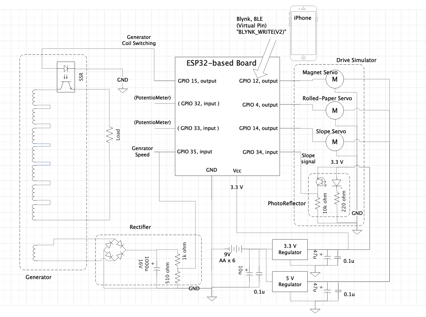
1) System Configuration
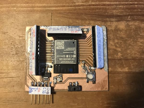
For the Drive Simulator, which would utilize 3 servo motors (SG90), I decided to make ESP32-based MCU, so that it can communicate with other devices like iPhone via wifi or BLE.
output 1 ; servo motor for rolled paper control ( SG90-HV (continuous rotation))
output 2 ; servo motor for magnet control ( SG90-HV (continuous rotation))
output 3 ; servo motor for slope control ( SG90 (lever-motion))
output 4 ; SSR (Solid State Relay) control to ON/OFF the generator coil
input 1 ; generator speed in terms of voltage from 1 coil (out of 8 coils)
input 2 ; slope signal from photo reflector on the drive simulator
input 3 (BLYNK BLE) ; X-Y of JOYSTICK module to control the above output 1 and 2
input 4, 5, 6 ; potentiometers for trouble shooting ( substitution of the above input 1, 2, 3, if needed)
2) Controller
| EAGLE CAD , schematic | |
|---|---|
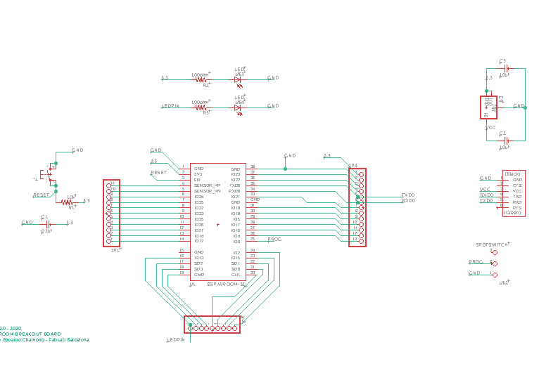 |
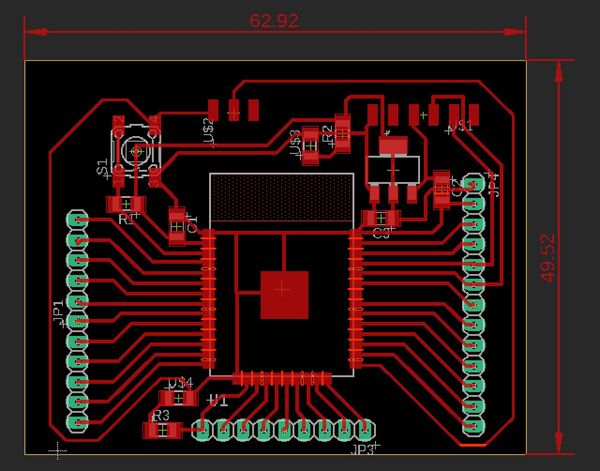 |
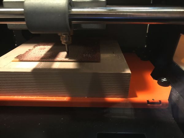
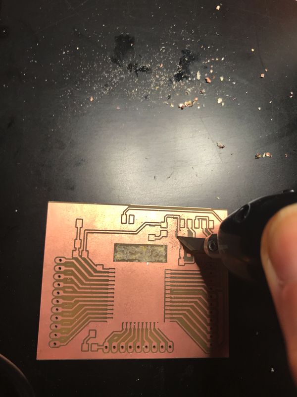
milling on SRM20
 |
 |
| put some pin-number labels | |
|---|---|
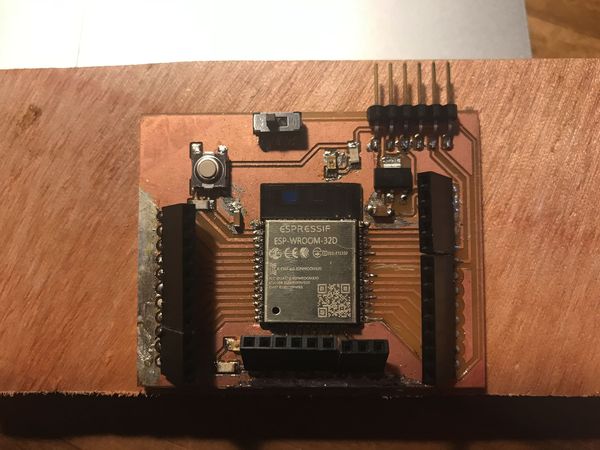 |
 |
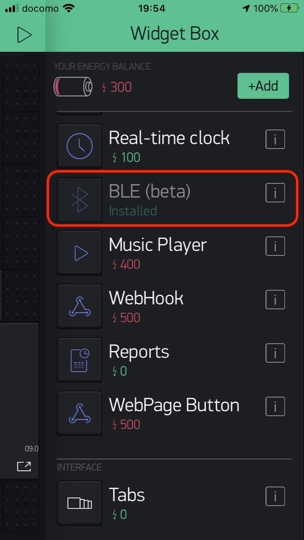
3) setting Blynk BLE
Regarding the setting of “Blynk BLE” on Arduino IDE and Blynk APP ( iPhone ), please refer ” 12. Interface and Application Programming , Group assignment Page “
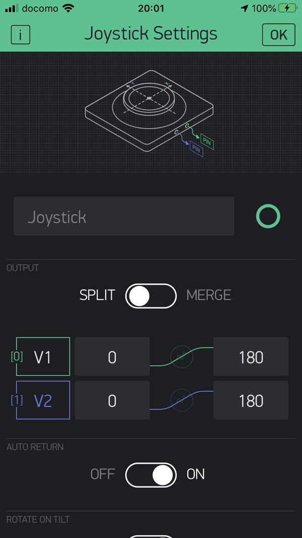
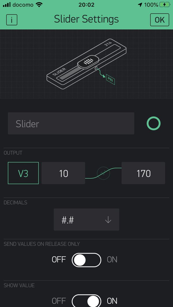
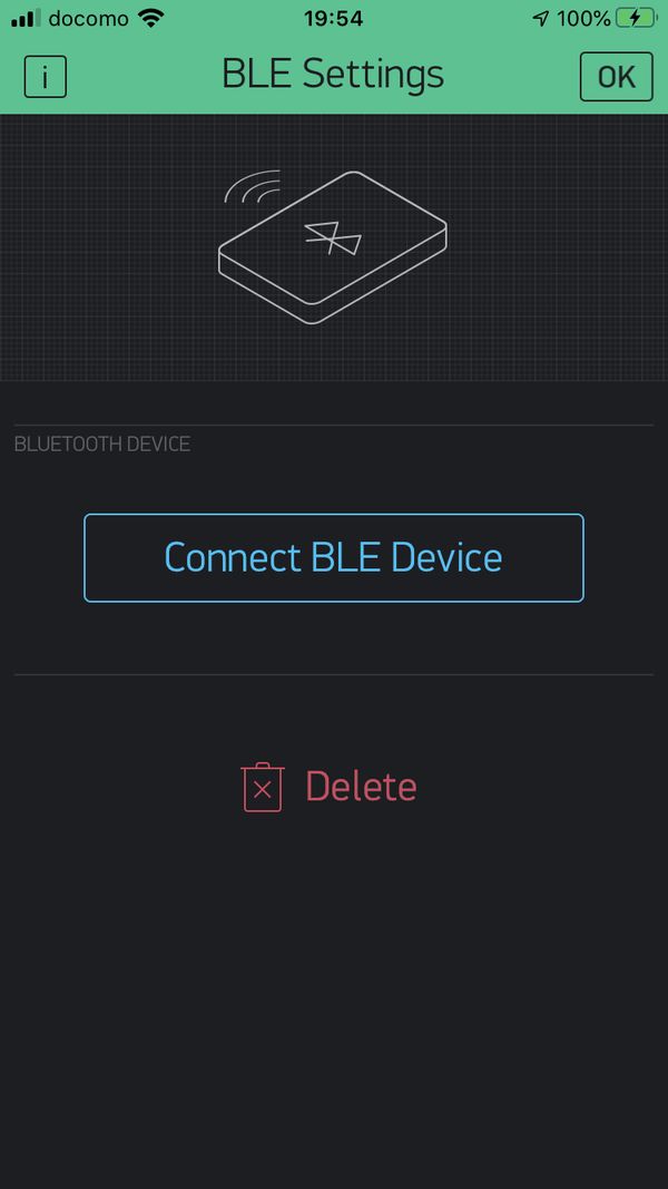
In my iPhone, I added the Blynk “Widget” such as, BLE (beta), Slider and Joystick.
 |
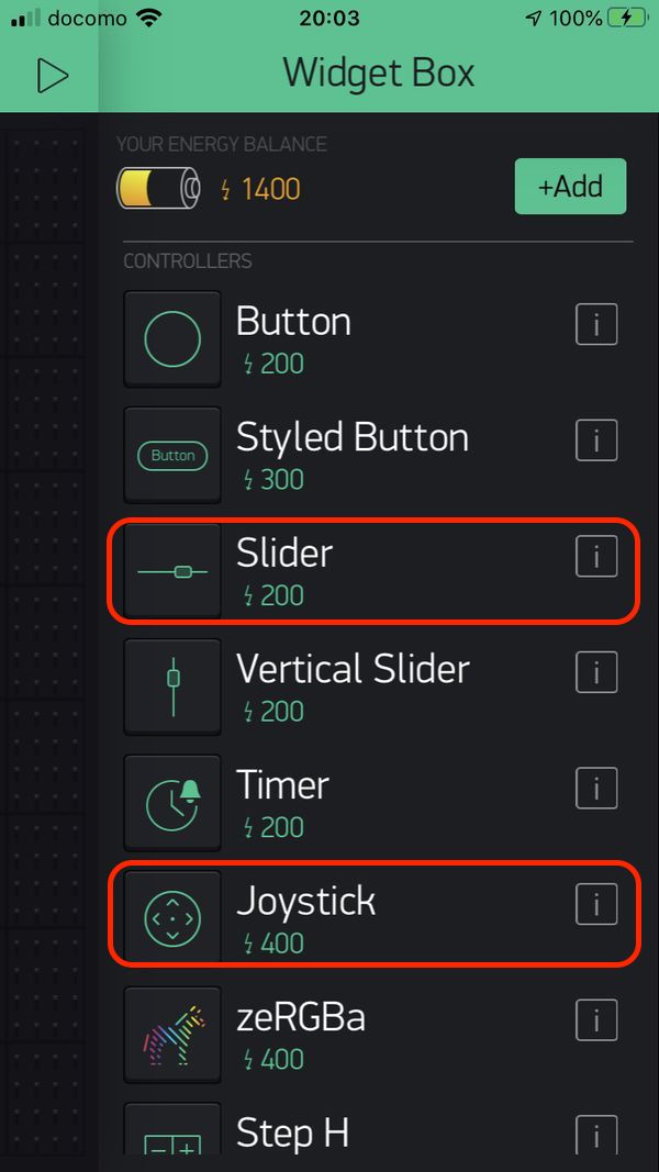 |
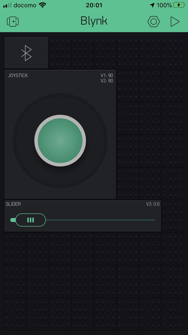
And set the parameters of the Widgets.
Joystick (SPLIT mode)
( In case of SPLIT mode, X-Y two parameters can be set separately. )
V1 for servo motor 1 min 0 - max 180
V2 for servo motor 2 min 0 - max 180
( “servo motor 1 and 2” are continuous rotation type, to control the Drive simulator shown in the video below. The values correspond to the speeds/directions of each servo motors. )
Slider
V3 for servo motor 3 min 10 - max 170
( “servo motor 3” is angle type, to control the slope of Drive simulator course shown in the video below. The value corresponds to the angle of servo lever. For the safe operation, the min/max value are set to be smaller than its allowable range. )
 |
 |
 |
 |
4) Blynk-only Mode
Control the Drive-Simulator by using Blynk BLE ( from iPhone ) only. In this case, generator is not used.
“ESP32_Blynk_BLE_DriveSim_servo.ino”
#define BLYNK_PRINT Serial

#define BLYNK_USE_DIRECT_CONNECT

#include <BlynkSimpleEsp32_BLE.h>
#include <BLEDevice.h>
#include <BLEServer.h>


#include <ESP32Servo.h>

// You should get Auth Token in the Blynk App.
// Go to the Project Settings (nut icon).
char auth[] = "Your Auth Token";

// create three servo objects
Servo servo1;
Servo servo2;
Servo servo3;

BLYNK_WRITE(V1)
{
  servo1.write(param.asInt());
}

BLYNK_WRITE(V2)
{
  servo2.write(param.asInt());
}

BLYNK_WRITE(V3)
{
  servo3.write(param.asInt());
}


void setup() {

  {
    // Debug console
    Serial.begin(9600);
    Serial.println("Waiting for connections...");

    Blynk.setDeviceName("Blynk");

    Blynk.begin(auth);

    servo1.attach(4);
    servo2.attach(12);
    servo3.attach(14);

  }


}

void loop()

{
  Blynk.run();
}
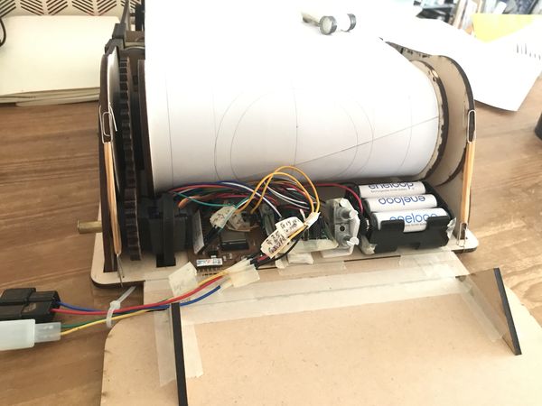
Then, I did set the MCU and battery ( “eneloop” Ni-MH, rechargeable ), tested the “drivability ” from my iPhone. It worked fine.
 |
 |
( During this test, I controlled “output3, slope ” from BLYNK using the “v3” parameter in the program. )
5) Generator Mode
In this case, Both of the “Generator” and the “Blynk BLE ( iPhone )” are used.
“ESP32_Blynk_BLE_DriveSim_servo_Gen_accel_rev1.ino”
#define BLYNK_PRINT Serial

#define BLYNK_USE_DIRECT_CONNECT

#include <BlynkSimpleEsp32_BLE.h>
#include <BLEDevice.h>
#include <BLEServer.h>


#include <ESP32Servo.h>

// You should get Auth Token in the Blynk App.
// Go to the Project Settings (nut icon).
char auth[] = "Your Auth Token";

Servo servo1;  // rolled paper
Servo servo2;  // magnet
Servo servo3;  // slope

BLYNK_WRITE(V2)
{
  servo2.write(param.asInt());   // magnet control by Blynk
}


void setup() {

  pinMode(35, INPUT);  // generator speed
  pinMode(34, INPUT);  // slope photorefrector

  pinMode(4, OUTPUT);   // rolled paper
  pinMode(14, OUTPUT);  // slope servo
  pinMode(15, OUTPUT);  // SSR for generator coil switching

  servo1.attach(4);
  servo3.attach(14);

  {
    // Debug console
    Serial.begin(9600);
    Serial.println("Waiting for connections...");

    Blynk.setDeviceName("Blynk");

    Blynk.begin(auth);

    servo2.attach(12);  // magnet control by Blynk

  }

}

void loop()

{
  Blynk.run();

  int val1 = analogRead(35);  // generator speed
  int val3 = analogRead(34);  // slope photorefrector

  int angle1 = map(val1, 0, 3600, 90, 180);  // generator speed
//  int angle3 = map(val3, 0, 4095, 140, 178);  // slope photorefrector


  servo1.write(angle1); // rolled paper speed by generator speed

  if (val3 < 2000) {
    digitalWrite(15, HIGH);
    servo3.write(140);  // slope high
  } else {
    digitalWrite(15, LOW);
    servo3.write(178);  // slope low
  }

}
Wk23 (2020/07/11) “Generator Testing, Assembly, Presentation Preparation”
1) Generator Testing
a) Test method
-
Purpose ; To check the Generator Output Power, while driving it with the reasonable ” Leg speed & load ” as an exercise machine without any problems
-
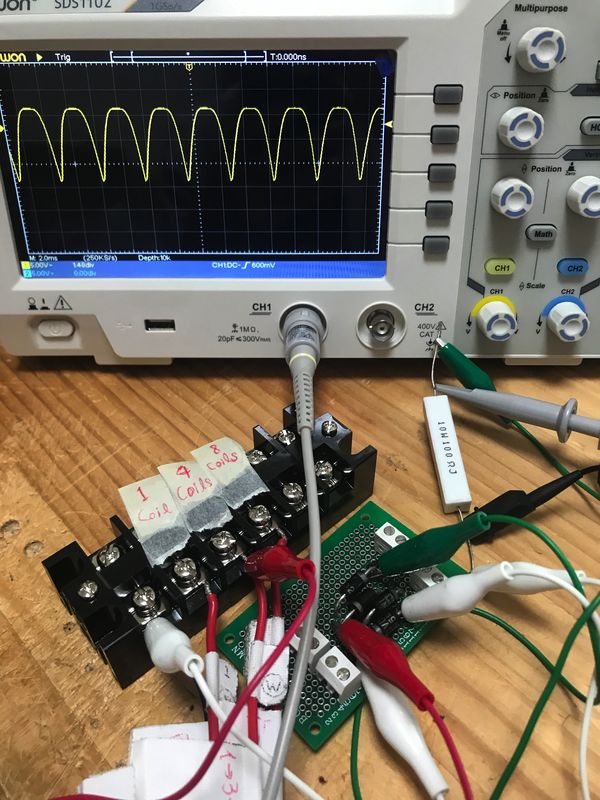
Generator output wiring were connected to cement resister through a rectifier.
-
measurement ; oscilloscope to check the wave form, Digital multimeter to check DC voltage of rectifier ( + 1000 uF capacitor ) output
( This time, Generator speed was not measured, because I didn’t have appropriate equipments or time. )
- Testing parameters ; number of generator coils, resistance (ohm) as the electric load
 |
 |
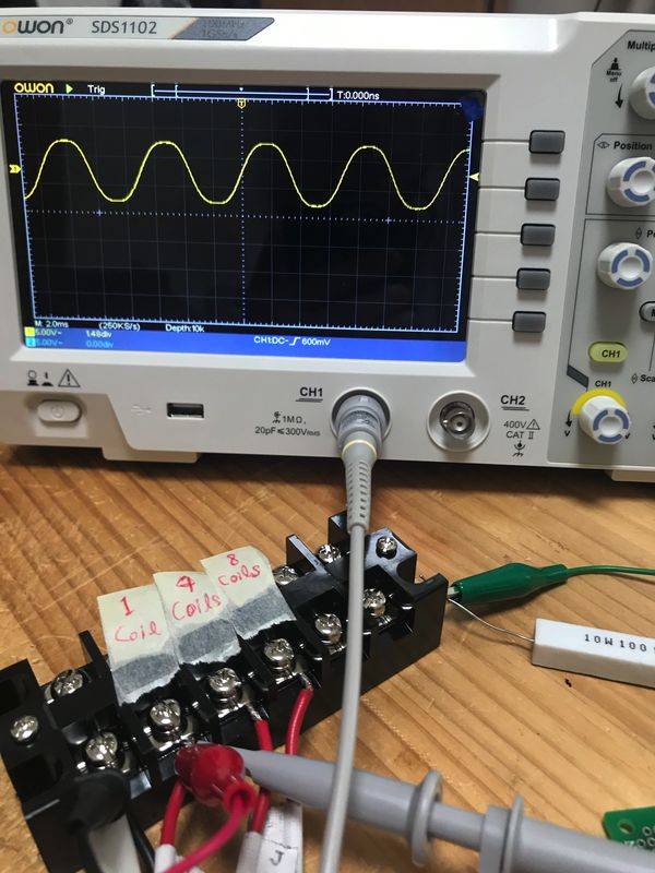
- wave form observation
| 1 Coil, 100 ohm Resistor, about 10 volt (peak-to-peak) sin wave. | 1 Coil, 100 ohm Resistor, after rectifier (no capacitor) |
|---|---|
 |
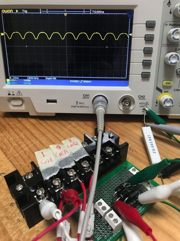 |
| 4 Coil, 100 ohm Resistor, after rectifier (no capacitor) | ( after the generator testing, mockup of the simulator table for 3D modeling was made. ) |
|---|---|
 |
 |
b) Test results
| Test No. |
Resister ohm |
Number of coils |
Output DC voltage V |
Output Power W |
Problem |
|---|---|---|---|---|---|
| 1 | 100 | 1 | 6.6 | 0.44 | |
| 2 | 100 | 4 | 23 | 5.3 | |
| 3 | 100 | 8 | 42 | 17.6 | |
| 4 | 50 | 1 | 6.4 | 0.82 | |
| 5 | 50 | 4 | 23 | 11 | |
| 6 | 50 | 7 | 27 | 14.6 | |
| 7 | 50 | 8 | 34 | 23.1 | |
| 8 | 20 | 1 | 6.0 | 1.8 | |
| 9 | 20 | 4 | 18 | 16.2 | |
| 10 | 20 | 8 | 22 | 24.2 | belt slip |
| 11 | 10 | 1 | 5.3 | 2.8 | |
| 12 | 10 | 4 | 14 | 19.6 | belt slip |
| 13 | 10 | 8 | 12 | 14.4 | belt slip |
-
With 10 ohm resistor, the leg load ( resistance of the sliders ) is high, and the timing belts connected to the sliders slipped on the pulley. ( Test No. 13, 12 )
-
The same thing happened with 20 ohm resistor and 8 coils of generator. ( Test No. 10 )
-
Maximum output power so far was 23.1 watts, it was with 50 ohm resistor and 8 coils. Also, the leg load was comfortable level. ( Test No. 7 )
-
With 50 ohm resistor and 7 coils, the output power was 14.6 watts, and it’s still enough to charge smart phones. ( Test No. 6 )
c) Conclusion
-
Out of the 8 coils in the generator, use 7 coils for charging, use remaining one for controlling the Drive Simulator.
-
As the input voltage of ESP32 is below 3.3 V, select the appropriate resistor for the voltage divider between the above 1 coil output and ESP32.
( and, they were 1 k ohm and 510 ohm. )
- the above 2 items has been reflected to the circuit diagram in ” Wk22 (2020/07/01) “Control System” 1) System Configuration “
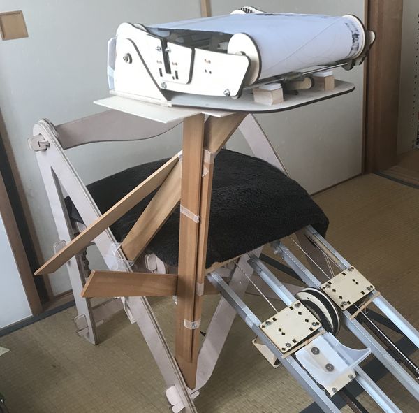
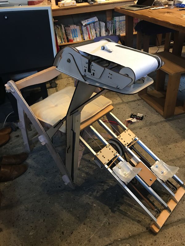
2) Assembly, Presentation Preparation
Laser cut the table, then, set the Drive simulator.
| to reinforce the bottom portion of the table, a wooden bar was attached. | |
|---|---|
 |
 |
 |
 |
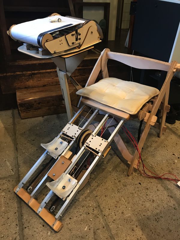
It’s ( almost ) perfect, as I planned.
After the “Project Presentation”
1) Some improvements
To exhibit this project at Maker Faire Tokyo, I improved mainly 2 items as follows.
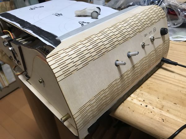
(1) Drive Simulator
-
Rear cover
-
Power supply
Before ; 6 AA batteries ( about 1.5V x 6 = 9V ) + 5V voltage regulator
After ; AC adapter ( AC100V to DC5V, switching regulator) + 1A fuse
Originally, I planed to use Ni-MH (Nickel Metal Hydride) rechargeable batteries which were supposed to be charged by leg power ( via Generator ), but I found that the 5V regulator was getting hot during the operation. As it was expected that I would demonstrate it for about 10 hours during this 2-day event, I decided to utilize AC adapter with switching regulator in order to handle the demonstration safely.
Also, I added some Switches and Potentiometers on the Rear cover for possible improvements in the future.
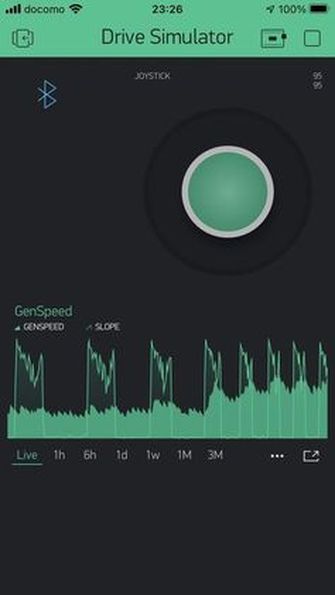
(2) BLYNK app for iPhone
I added the graphs to monitor “Generator speed” & “Slope signal” during the operation.
| bottom right ; a cable from AC adaptor from top right ; fuse case, switches, potentiometers |
on the bottom ; “Generator speed” & “Slope signal” |
|---|---|
 |
 |
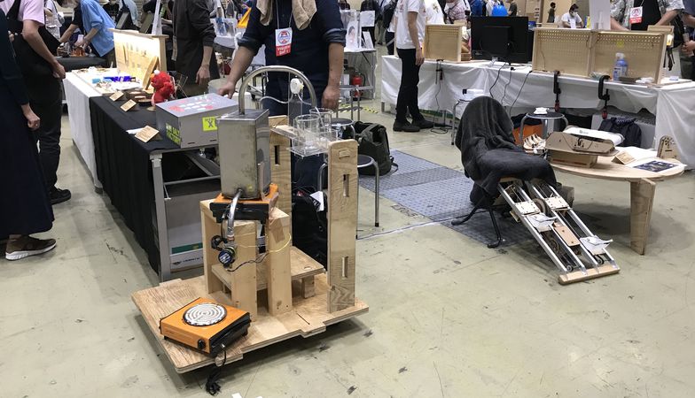
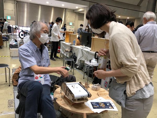
2) Exhibiting the Final Project at Maker Faire Tokyo 2020 (2020/10/03-04)
Thanks to Fablab Kamakura people, we had an opportunity to exhibit some examples of the Final Projects and weekly assignments.
| FabAcademy2020 booth | Coil winder and Small Generator on the table |
|---|---|
 |
 |
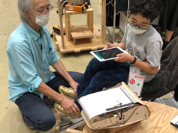
I had about 15 to 20 people try it out, and got a lot of insights.
There were a few people who could not manipulate the pedals and sliders properly. Because they stepped on the edge of the pedals, the pedals would tilt, and the rollers and bolts would interfere with the inside of the slider, as a result, the pedals would not move smoothly. In my case, I don’t feel any problems with the operation. My body remembers where to step on the pedals. (This is a common pitfall when developing individually or with a small group. ) I knew this problem was possible, but it was good to see the reactions of people operating it for the first time. In any case, I’ll keep improving it.
The slider system was too large for children and needs to be made adjustable ( position and stroke ).
The driving simulator was nice to catch people’s attention, but as a game, I want it to be more fun.
| some damaged inner surface of slider | some contacting marks on Stud bolts and Nuts |
|---|---|
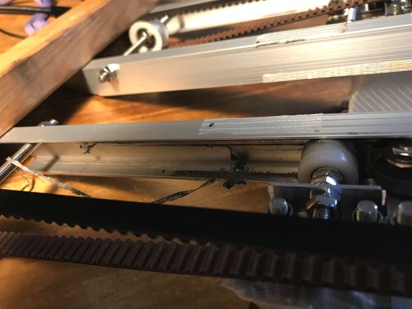 |
 |
| a kind of durability test during the 2-day event | helping the legs to drive Generator |
|---|---|
 |
 |
3) Further schedule
-
charging DC 12V battery system
-
hand powered item
-
wireless communication between generator control and simulator control
-
haptic items of the Drive simulator