2. Computer Aided design
This week assigment
Assignment of this week is to model (raster, vector, 2D, 3D, render, animate, simulate, …) a possible final project, and post it on my class page.
Final Project drawing
I drew the final project drawing with SketchUp.
I have no knowledge of motor and gear construction and combination of electronic boards.
So this time, I tried to draw a rough image.
I announce the process.
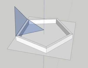
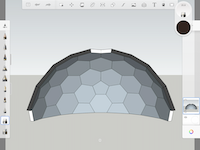
- Create the base for window drawing
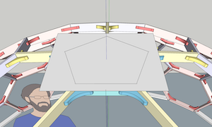
- Attach a pentagonal frame and one acrylic transparent plate (Closed and open)
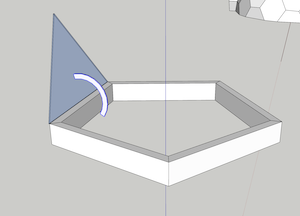
- Temporarily attach a stay for opening and closing (Actually this is geared) This may not be the best way to open and close, but this is the only way to go.
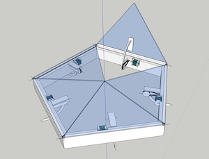
- When I closed it, I found that the stay was going through the roof
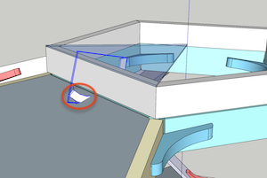
- I cut the stay, reinforced it, and wrote it in an open state and a closed state.
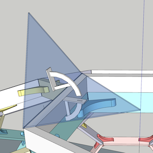
- I tried opening and closing. It doesn’t seem to interfere anywhere.
- Temporarily put on gear (Not jagged)
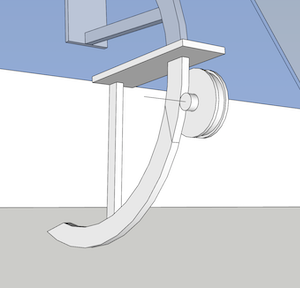
- With a small gear
I don’t know how to transmit the power and how to adjust the speed, but I need to check it later.
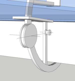
- Attach a belt that conveys the power of the motor
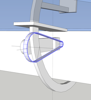
- I turned on the motor I don’t know if this is also a direct connection, but I need to look into it later.
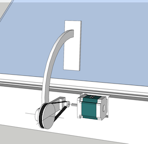
-
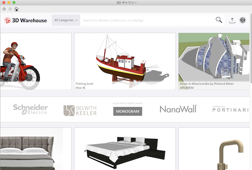
This motor was downloaded by searching for “stepping_motor” in the SketchUp 3D gallery. I used it after changing the scale.
-
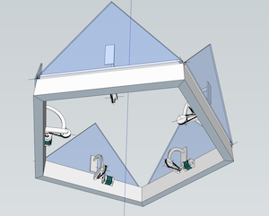
Rotate 72 ° around z-axis and copy 4 copies
- Picture seen from below (indoor)
- Download:Final Project plan_001 → Lotus_window001.skp
My cad background
3D
1. SketchUp
Two years ago, I first encountered 3Dcad (SketchUp). I was very excited at that time. Because, through the computer, the space drawn by the head appeared on the screen in a real way. SketchUp made it easy and intuitive.
Since then, dome house designs (mainly used for construction) have been created using SketchUp. Now I am considering creating a new dome house series, commercializing it and selling it.
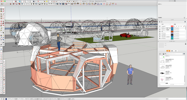
I was originally a carpenter, so I am good at the structure and construction of wood. The structure of the dome is made of domestic timber and is designed with the traditional Japanese timber frame.
And I noticed something interesting when using SketchUp. It is a fact that the world embodied in this software is actually made of the programming language “Ruby” and “numbers” (vectors).
・SketchUp-Ruby
As a concrete example, I would like to quote the Ruby editor for SketchUp created by MIT professor ALEXANDER C. SCHREYER and the explanation on YouTube.

- website - Sketchup-ruby-code-edhitor
- If you are more interested, read the following book.

・About Functions
- SketchUp is very easy and intuitive to operate.
The basic tools are as follows and general drawing is possible.

- There is push-pull as a characteristic tool.
Extrusion drawing can be performed in the 3D state.
- You can select a tool that fulfills the function as needed, or install and connect a plug-in from outside.
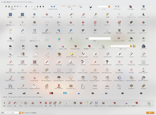
- There are plenty of 3D galleries so you can copy them.
・Buckminster Fuller World
A little departure from the lecture, but for me, the encounter between 3Dcad and Fuller was special, so I want to write a little.
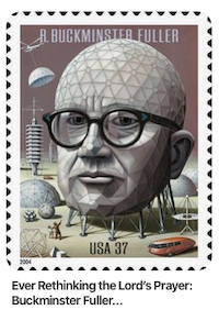
Book written about Synergetics

Fuller said:
Only by doing more with less can we realize dramatic and comprehensive possibilities for success.
Fuller called it the “Design Science Revolution.”
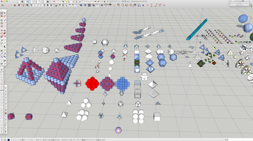
I reproduced almost all the figures in the COSMOGRAPHY book in 3D.
Here are some of them.
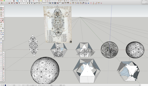
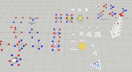
Fuller’s theory is esoteric, but it may actually be a simple law of the universe.
Powerful if this is integrated with FabLab’s manufacturing revolution
I don’t see the way yet, but I feel we can.
__
In short, I personally think SketchUp is good at making such intuitive drawings.
2. Rhynoceros
・Rhynoceros-python
For SketchUp Ruby, Rhinoceros can be programmed in Python.
According to my research, there are more 3Dcad using Python than Ruby, and more data and manuals.
To load Python code in Rhinoceros, use the Atom Editor. (For Mac)
First of all, you need to install “rhino-python” package in Atom Editor.

Next, execute the “StartAtomEditorListener” command in the command area of Rhinoceros.
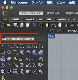
Start the atom, edit the Python script, save the file with a “.py” extension.
When editing is completed, press [control] + [option] + [r] keys on the keyboard with the atom active, the file will be sent to Rhinoceros, and the following screen will be displayed instantly.
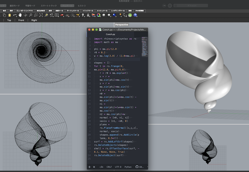
Download Rhinoceros File → shell.3dm
Great!!!
Here is a Python code sample of this snail, so please try it.
(Rhinoceros can be installed for free after a 90-day trial.)
import rhinoscriptsyntax as rs
import math as ma

phi = ma.pi/12.0
r0 = 0.2
w = ma.log(3.0) / (2.0*ma.pi)

shapes = []
for t in rs.frange(0, ma.pi*12.0, ma.pi/6.0):
    r = r0 * ma.exp(w*t)
    x = r * ma.sin(phi)*ma.cos(t)
    y = r * ma.sin(phi)*ma.sin(t)
    z = r * ma.cos(phi)
    n0 = ma.sin(phi)*(w*ma.cos(t) - ma.sin(t))
    n1 = ma.sin(phi)*(w*ma.sin(t) + ma.cos(t))
    n2 = ma.cos(phi)*w
    normal = [n0, n1, n2]
    xaxis = [n1, -n0, 0]
    plane = rs.PlaneFromNormal([x,y,z], normal, xaxis)
    shapes.append(rs.AddCircle(plane, 0.5*r))
surf = rs.AddLoftSrf(shapes)
rs.DeleteObjects(shapes)
shell = rs.OffsetSurface(surf, -0.1, None, None, True)
rs.DeleteObject(surf)
・Rhinoceros-Grasshopper
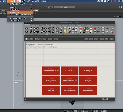
Rhinoceros comes with interesting features as standard, and I would like to try one of them, ‘Grasshopper’.
First, menu-> Tools-> Grasshopper
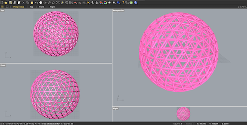
This time I read the data of Geodesic Dome which was already created as a sample.
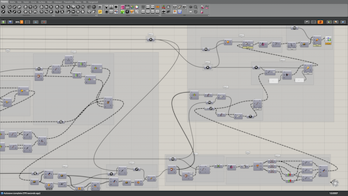
It is the whole image
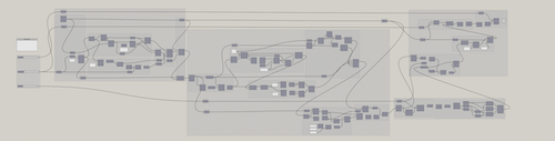
Then you will see the Geodesic Dome drawing at once!!!
Great!!!
Download File → Geodesic Dome_week3.gh
Grasshopper has a handy plug-in called a slider that allows you to change the size, number of divisions, pipe thickness, etc. in real time.
As my background
I am writing a 3D drawing using these SketchUp and Rhinoceros.
I’m still learning Ruby and Python programming.
What I want to do in the future is that I can estimate at the end of drawing with 3Dcad.
In other words, extract python cad data and link it with external data. We believe it will lead to more efficient operations.
New challenging CAD
3D
1. OpenSCAD
・CSG
Understand Constructive Solid Geometry while actually drawing with OpenSCAD.
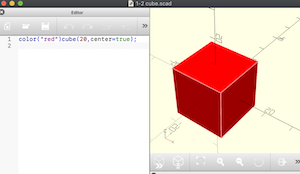
First, write a red square with the center at (0,0,0).
color("red")cube(20,center=true);
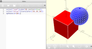
Next, write a blue sphere centered at (10,10,10).
color("blue")translate([10,10,10])
sphere(r=10);
Download File → union.scad
When I output it as an STL file, it is already a union.
However, in order to write the code clearly, it is better to specify union () as follows.
union() {  //union
color("red")cube(20,center=true);
color("blue")translate([10,10,10])
sphere(r=10);
}
__ Next, the difference. (The position of the sphere has been moved by -20 on the Y axis for easy viewing.)
difference() {  //difference
color("red")cube(20,center=true);
color("blue")translate([10,-10,10])
sphere(r=10);
}
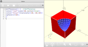
Download File → difference.scad
Next, the intersection.
intersection() {  //intersection
color("red")cube(20,center=true);
color("blue")translate([10,10,10])
sphere(r=10);
}
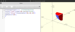
Download File → intersection.scad
As described above, CSG defines a shape by applying three Boolean operations of union, definition, and intersection to a simple basic solid group. It’s hard to believe, but this will create any complex shape. This is best understood by looking at the traditional carpentry connections (wood joints) of Japanese carpenters.
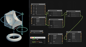
2. Antimony
Try CGS (defference) with Antimonuy
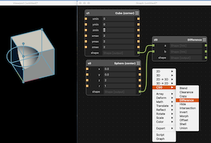
I tried script and {Repel}, but I didn’t understand much. I want to do the next task.
3. Fusion360
I usually draw using SketchUp, but thought that Fusion360 was better for processing CNC and other finer drawings (for example, screws).
I tried to load SketchUp drawings with Fusion360, but couldn’t edit them.
So, I tried to think that it could be done only with the machining drawings.
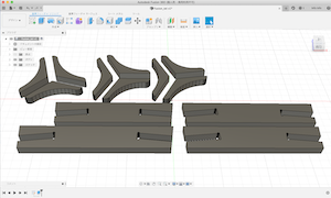
The frame and joints of the prototype dome drawn with SketchUp.
All these basic shapes can be assembled with these seven parts.
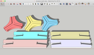
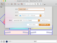
First, select these 7 parts and save them to the camera → Parallel projection → Plan view → Export → 2D graphic → DXF → Desktop.
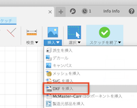
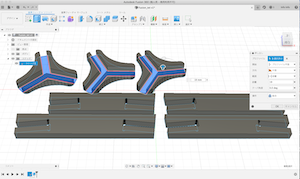
Next, call this dxf file with Fusion360.
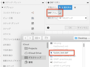
Successfully loaded!
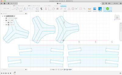
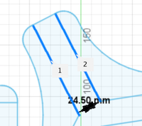
I checked the dimensions, but they copied it.
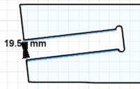
Finish sketch and extrude with extrude tool
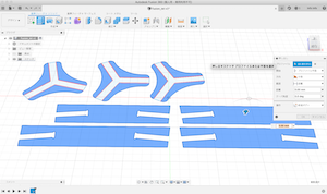
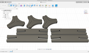
- Download:Dome_parts → dome_parts.f3d
I was able to draw safely.
By the way, I exported various files from SketchUp, including .skp, and uploaded them with Fusion360, but none of them could be edited correctly. I wanted to know if there was a way around here.
2D
1. FreeCAD
FreeCAD struggled with the operation anyway. My OS is a Mac, but it started when the lines didn’t disappear on delete click. I consulted with the instructor at Zoom, but it was not resolved. There are no shortcut keys. I tried it out and solved it, so record it for reference. Actually it was very easy. Most of the problems may be:
I clicked Tinky’s delete and was able to delete it! !

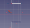
I change my mind and try 2D design.
For the time being, trimming and dimensional constraints were completed.
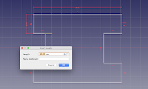
Next I tried 2D parametric I think this is a useful feature. I am interested in how it can be used in actual drawing, but I will do it for my future homework.
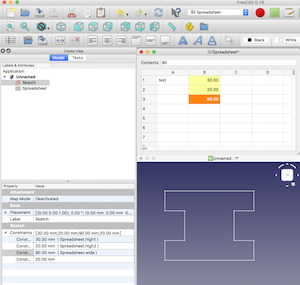
- free CAD file → practice.FCStd
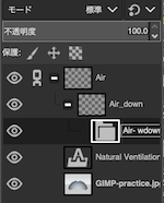
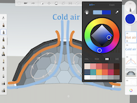
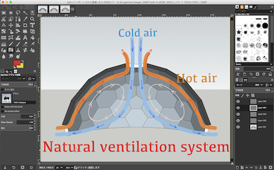
2. GIMP
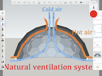
I want to use GIMP to make a 2D-looking air circulation diagram for my final project plan (not for now).
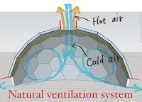
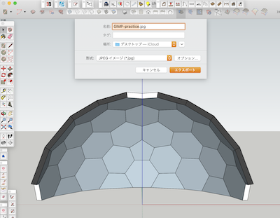
First, export the sectional view as a jpeg file from SketchUp.
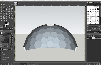
Read the file with GIMP
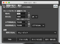
By the way, I learned that the size of the image file can be changed here.
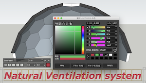
I was able to edit the characters in various ways.
It’s convenient to have a history so you can easily return to where you want to go.
Layers can also be divided into multiple layers.
I’ve done so far, but I can’t draw the arrow of the airflow I want to write this time, so it’s up to here.
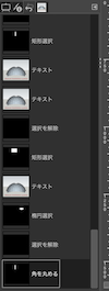
2. Sketchbook
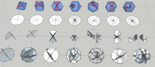
Try a new one on Sketchbook.
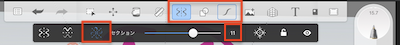
An interesting function was the target figure function.
① Select the function of the line (two including the target)
② Click the shape like a windmill
③ Select 360 ° assignment number
Then, they are displayed simultaneously like a photo.
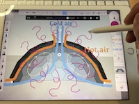
When I saved the sketchbook file, it was saved with a .psd file extension.
When you open it! The GIMP application has been launched.
After confirming, the layer was also separated from Chitin, so editing is also possible.
Chan-chan!
end
What I learned this week.
- How to upload and link Sketchfab
- Boolean operations of union, definition, and intersection by OpenSCAD
Constructive Solid Geometry - Boolean operations of union, definition, and intersection by Antimony
Antimony_video - Fusion360 Drafting Basics and SketchUp Alignment
- First drafting in FreeCAD
- Drafting with GIMP
- Drawing on iPad with SketchBook
Data download
- Final Project plan_001 → Lotus_window001.skp
- Rhinoceros shell file → shell.3dm
- Union.scad file → union.scad
- Difference.scad file → difference.scad
- Intersection.scad file → intersection.scad
- Dome_parts.Fusion360 → dome_parts.f3d
- Free CAD file → practice.FCStd
- GIMP_practice file → gimp practice file