Final Project
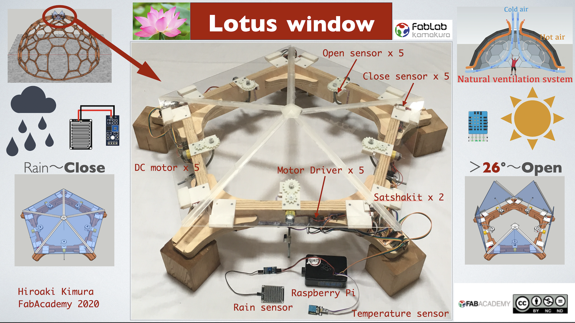
Lotus window presentation
Lotus window video
※ The windows in the video open and close at quadruple speed. x4
Features
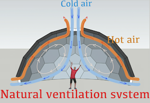
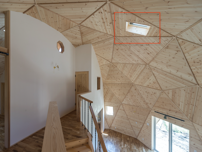
By placing these windows at the tops of dome houses and circular buildings, “cool downdrafts” and “warm updrafts” are generated and the air inside the dome naturally circulates as shown in the figure, creating a comfortable space.
The air inside the dome is automatically opened and closed by sensors.
- When the temperature inside the dome reaches or exceeds the set temperature, the window is opened.
- These actions are almost all automatic.
Therefore, the following sensor functions are attached.
input devices
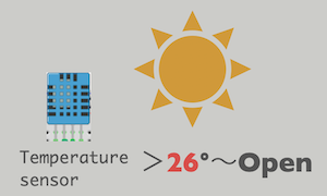
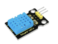
I used DHT11 Temperature and Humidity Sensoras a temperature sensor.
I learned these connections in the week of week09 input devices. For details, please click the link below.
Link to week09 input devices DHT11
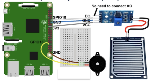
- When it starts to rain, the window will close.
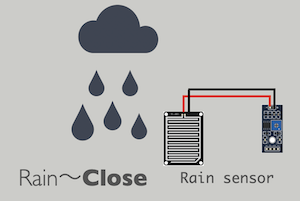
I selected the following sensor as a sensor to detect rain and connected it to the Raspberry Pi.
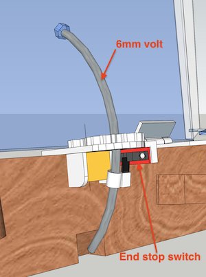
In addition, the following two types of sensors were used as limit sensors for opening and closing windows.
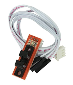
WINGONEER CNC 3D printer mechanical optical limit switch
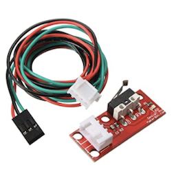
TOOHUI End stop switch Limit switch
The Origin of the Idea
Most skylights on the market today are square. So if you want to put a skylight in a dome or circular building, you still have to have a square opening. I was uncomfortable with this, so I decided to make my own pentagonal (triangular) opening and closing windows.
Also, there were remote-controlled open/close skylights, but I thought that if there was a skylight that automatically sensed the temperature and rain, it would prevent leaks in the room when it rained while I was away.
Also, when we return home in midsummer, the second floor of the house will be stuffed with hot air, and this discomfort will be greatly reduced by automatically opening and closing the skylight while we are away.
Design
For the 3D design, I used SketchUp.
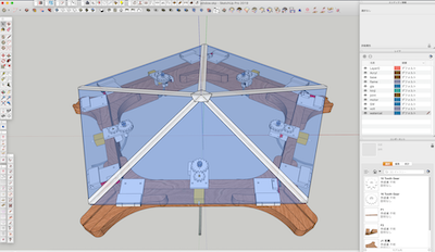
File download → Lotus_window.skp
The five clear acrylic windows open and close at 5 second intervals to avoid hitting each weather seal.
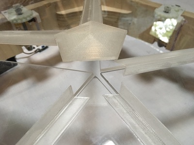
Since the movement of the windows is similar to the way the petals of a lotus flower open, the name “Lotus Window” was given to this window.
Some data suggests that indoor ventilation is an effective countermeasure against coronavirus, but with Lotus window, the ventilation can be controlled unattended 24 hours a day.
A natural ventilation system will be better for buildings and people than an enclosed space.
It also acts as a ventilation system for vinyl domes for growing vegetables and plants.
The most difficult part was how to open and close it
The photo of the base of my homemade equatorial mount gave me a big hint on how to do this. Thanks to Jun Kawahara who introduced me to the photo.
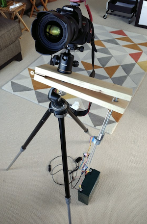
I also referred to this site as well as others.
Making a Curve Bolt Barn Door
How did I bend the bolt? Please see the video below for reference.
This was my first time making gear, so this time I downloaded the sample in SketchUp’s 3D Warehouse.
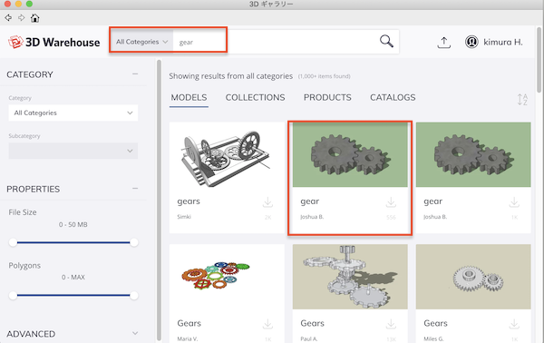
I modified it into a hexagonal nut shape and a DC motor shaft shape, and output it with a 3D printer.

I named this mechanism “Curve Bolt Barn Windows”. Below is a description of the output devices that power it.
output devices
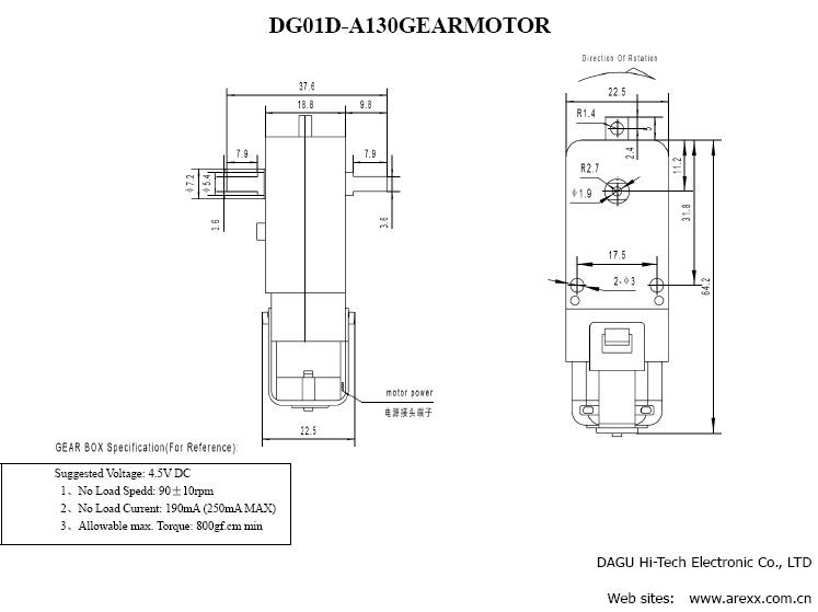
I used five DC geared motor
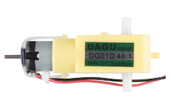
The built-in gear realizes high torque of 2 revolutions per second.
I chose this torque because I thought I needed this torque to open it.
For details about DC geard motor and motor driver (BD6222HFP), see the page of week11 output device in detail.
Link to week11 output device page
As a supplement, the consumption voltage and current measurement of DC moter is described on the group page.
Link to week11 group page kimura
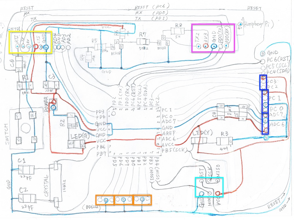
Board Design.
I wasn’t able to make a board because the lab was closed due to the effects of corona, so I first tested it using a breadboard and hand-drawn drawings.
As a concept, I planned a plan to open and close the five motors with a time difference by serializing the rain and temperature detected by the Raspberry Pi and communicating them serially to the two satshakits.
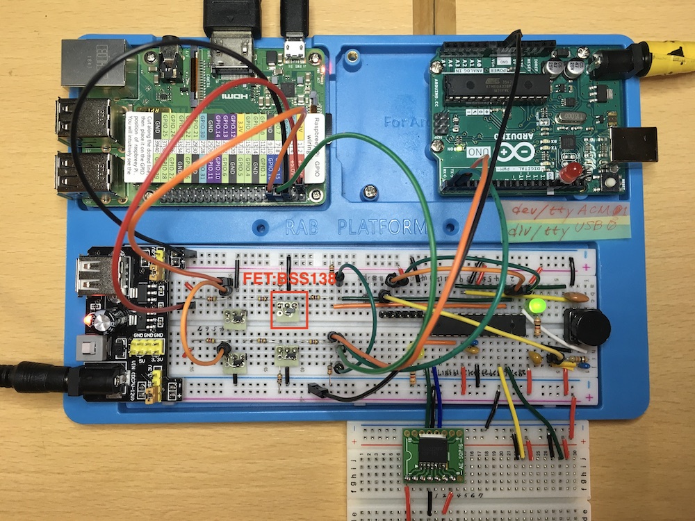
I named this satshakit “satsha_pi”. The meaning is a kit that can directly connect the existing satshakiti and Raspberry Pi.
See the week14 Networking weekly report for more information on these topics.
Link to week14 Networking page
I used Eagle to design the board.
Below is the data of satsha_pi.
File download .brd → satsha_pi.brd
File download .sch → satsha_pi.sch
Five motor driver (BD6222HFP) boards were made by dividing them into satsha_pi to facilitate later debugging. Below is the data.
File download .brd → DB6222.brd
File download .sch → DB6222.sch
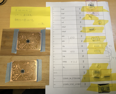
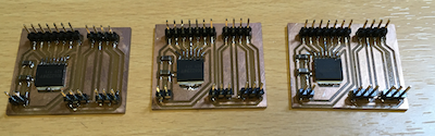
Board cutting
The lab was closed due to the corona, so we all made Eagle drawings and the instalactor checked them and sent them to Jun-san in the lab to process and send them to us remotely. Thank you very much.
After successfully soldering, I used Arduino to write the bootloader.
It was touching at the moment when my life came to life.
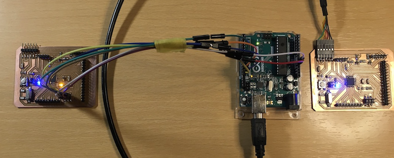
For writing the bootloader, I referred to the github page “Getting Started” chapter.
A motor driver and limit switch board has also been completed.
Wiring
The wiring was complex, so I’ve compiled a list. For wiring advice, I received a lot of advice from Mr. Yamamoto, a specialist. Thank you very much.
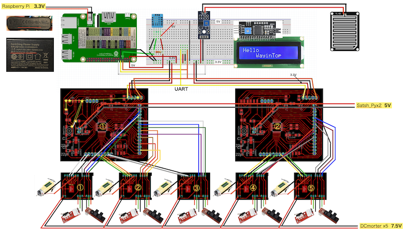
The sensor information is sent from the Raspberry Pi to satshakit via serial communication.
I used the Raspberry Pi simply because I like the python language and because I wanted to access the information on the web (weather forecast and train service status) from the Raspberry Pi and display the results visually on the LCD. I didn’t accomplish that task this time, but I’m grateful to my instructor Tsuchiya for her lots of advice on setting up and programming the Raspberry Pi.
Please see below for details of this content
Link to week14 Networking page
Processing.
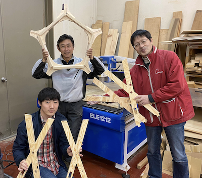
CNC
I used CNC for the wooden frame. We are very grateful to Mr. Muramatsu of FabLab Nagano of Shinshu University, we are indebted to Mr. Muramatsu for his help. Thank you very much for your help.
For details on CNC machining, please see the week7 computer controlled machig page (below).
Link Computer-controlled maching page
3D printing
Many parts, such as the hinge, motor base, gears, and drainer, were made at home using an inexpensive 3D printer. I purchased and created it. I’m satisfied with the accuracy and better than I expected.
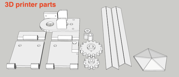
However, I learned that PLA filament is too soft and wears out quickly for the gears and other contact parts, so I should use a metal material for the rotating parts and use ball bearings for the rotating parts when actually making the product.
File download → Lotus_window.skp
programming
Raspberry Pi
rain_motor.py
1 2 3 4 5 6 7 8 9 10 11 12 13 14 15 16 17 18 19 20 21 22 23 24 25 26 27 28 29 30 31 32 33 34 35 36 37 38 39 40 41 42 43 44 45 46 47 | |
satsha_pi 1
Board connected to 3 motor drivers.
satsha1-motor3.ino
int M1rightP  = 5; //PD5 ~ connect 5.RIN
int M1leftP   = 6; //PD6 ~ connect 3.FIN
int M2rightP  = 7; //PD7 ~ connect 5.RIN
int M2leftP   = 8; //PB0 ~ connect 3.FIN
int M3rightP  = 9; //PB1 ~ connect 5.RIN
int M3leftP   = 10; //PB2 ~ connect 3.FIN

int M1open_Sensor = A4; // PC4 (SDA)
int M1close_Sensor = A5; // PC5 (SCL)
int M2open_Sensor = A0; // PC0
int M2close_Sensor = A1; // PC1
int M3open_Sensor = A2; // PC2
int M3close_Sensor = A3; // PC3

int val_1 = 0; // M1close_S = A5; // PC5 (SCL)
int val_2 = 0; // M1open_S = A4; // PC4 (SDA)
int val_3 = 0; // M2close_S = A1; // PC1
int val_4 = 0; // M2open_S = A0; // PC0
int val_5 = 0; // M3close_S = A3; // PC3
int val_6 = 0; // M3open_S = A2; // PC2

byte val=0;
#define LED_PIN 13

void setup()
{
  pinMode(M1leftP, OUTPUT);
  pinMode(M1rightP, OUTPUT);
  pinMode(M2leftP, OUTPUT);
  pinMode(M2rightP, OUTPUT);
  pinMode(M3leftP, OUTPUT);
  pinMode(M3rightP, OUTPUT);
  pinMode(LED_PIN, OUTPUT);

  Serial.begin(9600); // set up Serial library at 9600 bps
}

void loop()
{
    val_1 = analogRead(M1close_Sensor); // A5
    val_2 = analogRead(M1open_Sensor); // A4
    val_3 = analogRead(M2close_Sensor); // A1
    val_4 = analogRead(M2open_Sensor); // A0
    val_5 = analogRead(M3close_Sensor); // A3
    val_6 = analogRead(M3open_Sensor); // A2

    Serial.print("M1 close_Sensor_val_1:");
    Serial.println(val_1);
    Serial.print("M1 open_Sensor_val_2:");
    Serial.println(val_2);
    Serial.print("M2 close_Sensor_val_3:");
    Serial.println(val_3);
    Serial.print("M2 open_Sensor_val_4:");
    Serial.println(val_4);
    Serial.print("M3 close_Sensor_val_5:");
    Serial.println(val_5);
    Serial.print("M3 open_Sensor_val_6:");
    Serial.println(val_6);

    delay(200);

     if(Serial.available() > 0) {
        val = Serial.read();
     }
     // If you receive the serial number 1, M3leftP (left-handed, OPEN)
     if (val == '1' && val_1 < 800) {
         digitalWrite(M1leftP, HIGH);
         delay(5000);
         digitalWrite(M2leftP, HIGH);
         delay(5000);
         digitalWrite(M3leftP, HIGH);
         delay(5000);
     }
     if (val_2 > 800) {
         digitalWrite(M1leftP, LOW); // FIN-OFF
         delay(50);
     }
     if (val_4 > 800) {
         digitalWrite(M2leftP, LOW); // FIN-OFF
         delay(50);
     }
     if (val_6 > 800) {
         digitalWrite(M3leftP, LOW); // FIN-OFF
         delay(50);
     }

     // When the serial number 4 is sent, M3rightP (right-handed and closed)
     if (val == '4' && val_2 > 800) {
         delay(10000);
         digitalWrite(M3rightP, HIGH);
         delay(5000);
         digitalWrite(M2rightP, HIGH);
         delay(5000);
         digitalWrite(M1rightP, HIGH);
         delay(5000);
     }
     if (val_1 < 800) {
         digitalWrite(M1rightP, LOW); // FIN-OFF
         delay(50);
     }
     if (val_3 < 800) {
         digitalWrite(M2rightP, LOW); // FIN-OFF
         delay(50);
     }
     if (val_5 < 800) {
         digitalWrite(M3rightP, LOW); // FIN-OFF
         delay(50);
     }


 }
satsha_pi 2
Board connected to 2 motor drivers.
satsha-motor2.ino
int M4leftP   = 8; //PB0 ~ connect 3.FIN
int M4rightP  = 7; //PD7 ~ connect 5.RIN
int M5leftP   = 10; //PB2 ~ connect 3.FIN
int M5rightP  = 9; //PB1 ~ connect 5.RIN

int M4ruptPin1 = A1; // PC1
int val_7 = 0; // variable to store the value coming from the sensor
int M4ruptPin2 = A0; // PC0
int val_8 = 0; // variable to store the value coming from the sensor
int M5ruptPin1 = A3; // PC3
int val_9= 0; // variable to store the value coming from the sensor
int M5ruptPin2 = A2; // PC2
int val_10 = 0; // variable to store the value coming from the sensor

byte val=0;
#define LED_PIN 13

void setup()
{
  pinMode(M4leftP, OUTPUT);
  pinMode(M4rightP, OUTPUT);
  pinMode(M5leftP, OUTPUT);
  pinMode(M5rightP, OUTPUT);
  pinMode(LED_PIN, OUTPUT);

  Serial.begin(9600); // set up Serial library at 9600 bps
}

void loop()
{
  val_7 = analogRead(M4ruptPin1); // A1
  val_8 = analogRead(M4ruptPin2); // A0
  val_9 = analogRead(M5ruptPin1); // A3
  val_10 = analogRead(M5ruptPin2); // A2
  Serial.print("val_7:");
  Serial.println(val_7);
  Serial.print("val_8:");
  Serial.println(val_8);
  Serial.print("val_9:");
  Serial.println(val_9);
  Serial.print("val_10:");
  Serial.println(val_10);
  delay(200);

     if(Serial.available() > 0) {
        val = Serial.read();
     }
     // When you receive the serial number 2, M3leftP (left turn, OPEN)
     if (val == '1' && val_7 < 800) {
         delay(15000);
         digitalWrite(M4leftP, HIGH);
         delay(5000);
         digitalWrite(M5leftP, HIGH);
         delay(5000);
     }
     if (val_8 > 800) {
         digitalWrite(M4leftP, LOW); // FIN-OFF
         delay(50);
     }
     if (val_10 > 800) {
         digitalWrite(M5leftP, LOW); // FIN-OFF
         delay(50);
     }

     // When the serial number 4 is sent, M3rightP (right-handed and closed)
     if (val == '4' && val_8 > 800) {
         digitalWrite(M5rightP, HIGH);
         delay(5000);
         digitalWrite(M4rightP, HIGH);
         delay(5000);
     }
     if (val_7 < 800) {
         digitalWrite(M4rightP, LOW); // FIN-OFF
         delay(50);
     }
     if (val_9 < 800) {
         digitalWrite(M5rightP, LOW); // FIN-OFF
         delay(50);
     }

 }
Materials
| Qty | Description | Price | Link | Notes |
|---|---|---|---|---|
| 5 | DC geared motor | ¥1255 | https://www.switch-science.com/catalog/2793/ | Order many |
| 5 | TOOHUI end switch | ¥890 | https://www.amazon.co.jp/gp/product/B07W91FFKD/ref=ppx_yo_dt_b_asin_title_o00_s00?ie=UTF8&psc=1 | |
| 5 | Rain senser | ¥780 | https://www.amazon.co.jp/gp/product/B01N1GOC7S/ref=ppx_yo_dt_b_asin_title_o07_s00?ie=UTF8&psc=1 | |
| 5 | WINGONEER end switch | ¥899 | https://www.amazon.co.jp/gp/product/B077X8XL56/ref=ppx_yo_dt_b_asin_title_o08_s00?ie=UTF8&psc=1 | |
| 1 | 24mm plywood 1/2 | ¥1500 | ||
| 1 | Temprature/Humidity senser | class kit | https://wiki.keyestudio.com/Ks0034_keyestudio_DHT11_Temperature_and_Humidity_Sensor | |
| 2 | Acryl board | ¥9112 | watahan home center | |
| 2 | 6mm volt 1m | ¥322 | watahan home center | |
| 1box | bis | ¥280 | watahan home center | |
| 1set | Acryl volt | ¥305 | watahan home center | |
| 1set | Nat 6mm | ¥192 | watahan home center |