Wildcard Week
This week we were supposed to Design and produce something with a digital fabrication process (incorporating computer-aided design and manufacturing) not covered in another assignment, documenting the requirements that your assignment meets, and including everything necessary to reproduce it. Possibilities include (but are not limited to) composites, textiles, biotechnology, robotics, folding, and cooking.
I decided to make Pentagon shape Bowl of composite so for that I desined the negative and positive part of it on Nx-11.
Lets first come to the basics!!!!
What are Composites?
A composite material can be defined as a combination of a matrix and a reinforcement, which when combined gives properties superior to the properties of the individual components. In the case of a composite, the reinforcement is the fibers and is used to fortify the matrix in terms of strength and stiffness. The reinforcement fibers can be cut, aligned, placed in different ways to affect the properties of the resulting composite. The matrix, normally a form of resin, keeps the reinforcement in the desired orientation. It protects the reinforcement from chemical and environmental attack, and it bonds the reinforcement so that applied loads can be effectively transferred.
I want to make composite bowl.So for that I desined pentagon shape bowl on NX-11.
Source~ Wiki
When Should you use Composites ?
As with all engineering materials, composites have particular strengths and weaknesses, which should be considered at the specifying stage. Composites are by no means the right material for every job.
However, a major driving force behind the development of composites has been that the combination of the reinforcement and the matrix can be changed to meet the required final properties of a component. For example, if the final component needs to be fire-resistant, a fire-retardant matrix can be used in the development stage so that it has this property.
Weight reduction
>The primary reason composites are chosen is improved specific strength / stiffness (strength / stiffness specific per unit weight).
>This helps to reduce fuel use, or increase acceleration or range in transport.
>It allows for easier, faster installation or faster movement of robot arms and reduces supporting structures or foundations.
>It improves topside stability in vessels and offshore structures and buoyancy for deep sea applications.
Durability and maintenance
>Composites don’t rust, which is crucial, especially in marine and chemical environments. The need for maintenance and painting is reduced or eliminated.
>Composite bearings for marine engines and bridges need no lubrication and don’t corrode.
>Combine the excellent fatigue resistance, and composites can increase product lifespan by several times in many applications.
Added functionality
>Composites are thermal insulators which is good for fire and blast protection or cryogenic applications.
>Electrical insulation is useful for railway lineside structures and radar transparency. A conductive mesh or coating can be integrated if needed, e.g. to reflect radar or divert lightning.
>Sensors, electronics and cabling can be embedded.
Design freedom
>Composites design allows for freedom of architectural form.
>Many parts can be consolidated into one, and stiffeners, inserts, etc. can be integrated in-mould.
>Composites can be tailored to suit the application by choosing the constituent materials and embedding extra functionality.
Source~
https://compositesuk.co.uk/composite-materials/introduction
Bowl Design On NX
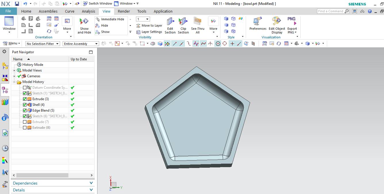
This is the negative part which is made by taking Pentagon from polygon and after extruding. The shell command is used and edge blend is used to round corners.

This is the positive part.It is made by extruding pentgon and rounding the Edges.
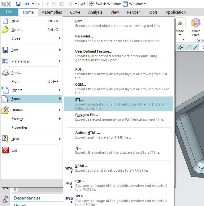
Now the final step for making design ready to create the tool path is to export it in STL format
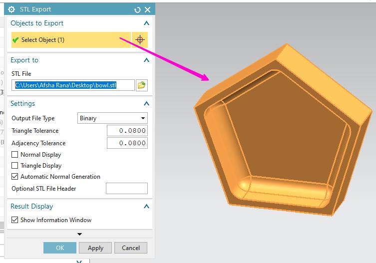
Select the object to convert to STL and give the location to save it.
Toolpath on Aspire
For creating tool path,First import the stl file of moedel into aspire and in moelling tab click onn the icon shows to select the vector for cutting.

Select roughing operation to get the tool path and select the tool diameter.

I selected 6mm tool for roughing.


For further details you can check the process in my Computer Controlled Machining Week
Animation for cutting:
Soft Robot Gripper
First I searched for Soft robotic gripper and I find this tutorial very helpful and got the process and go through various others
I decided to make soft gripper also.
Design on NX-11
For making the gripper, First I designed the shape of both mold required to produce soft mold.
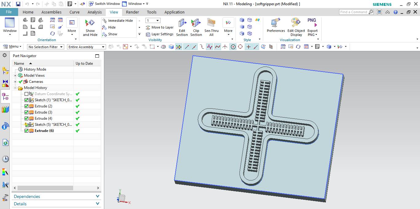
First I decide to make the mold with the help of SRM-20.So included the base.
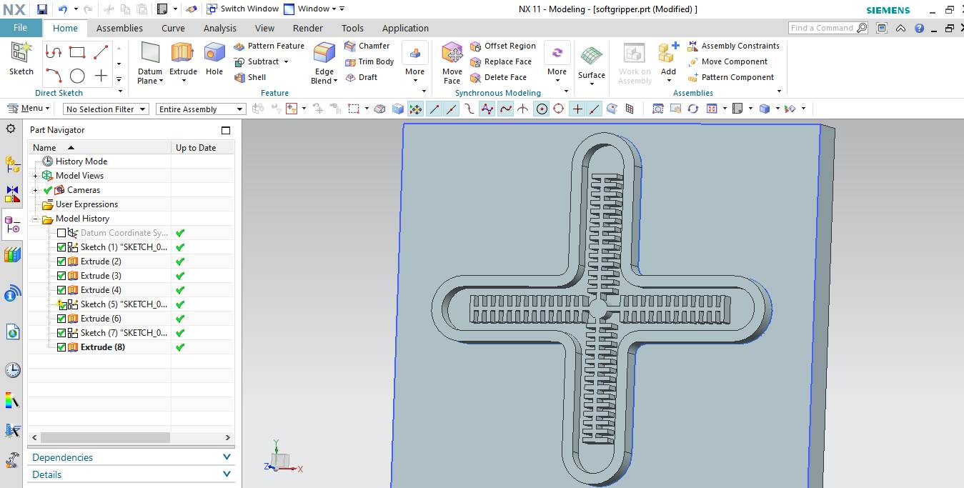
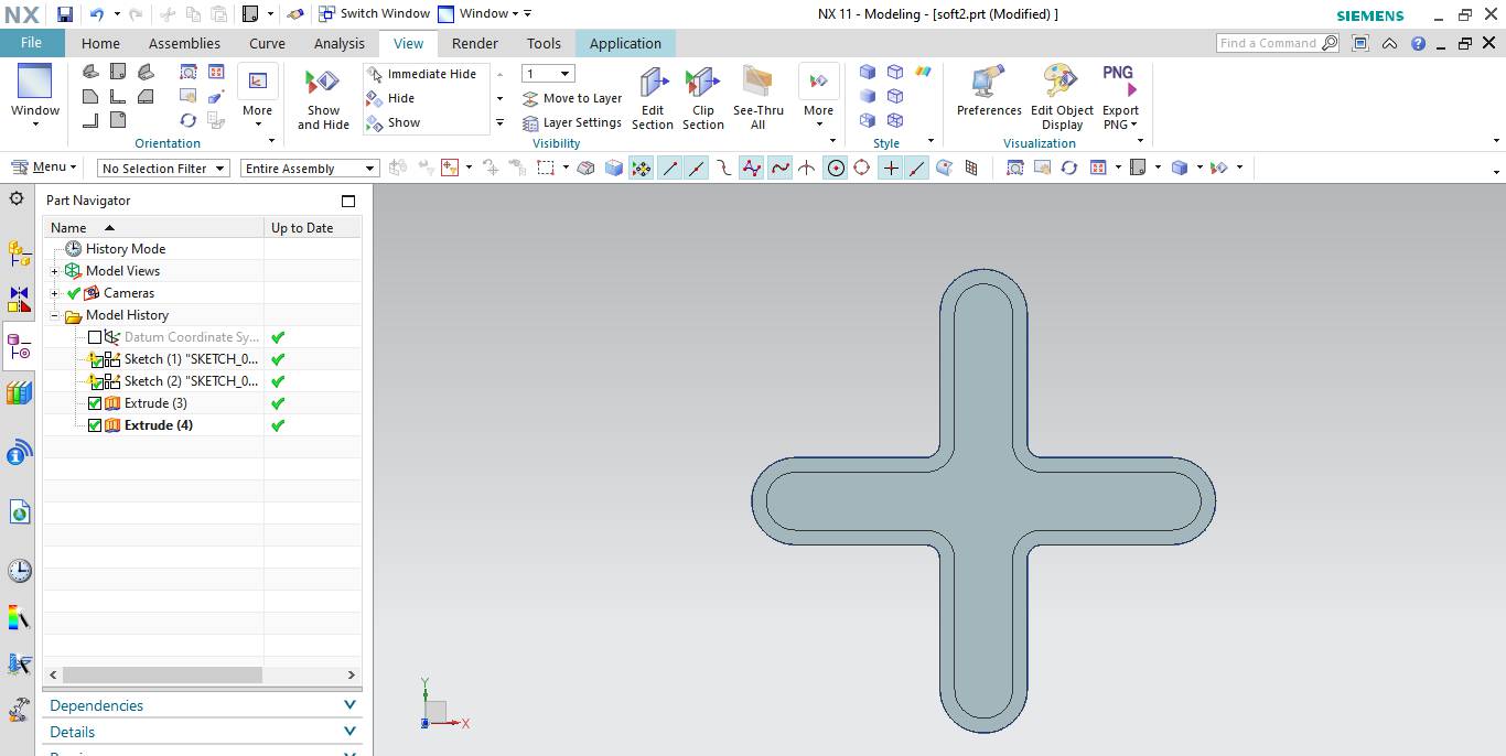
Later I decided to switch to 3D-Printing. I made two mold one having channels for passing the pressurised air and other to paste it to top of tha channelled mold.
3D-Printing of Mold
For 3D Print, I will print it on Makerbot-Replicator Z-18.
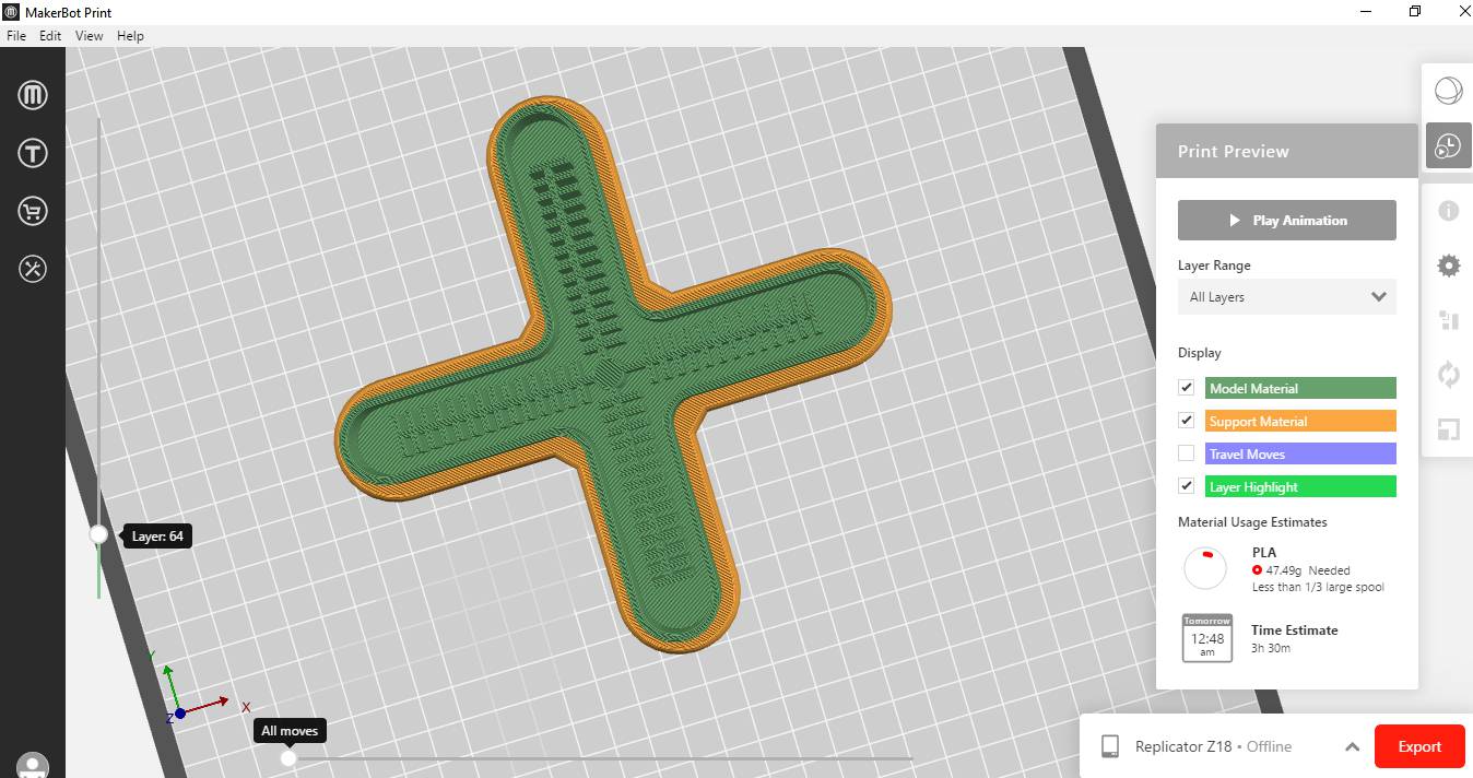
I used Makerbot print software to make the strategy for 3D Printitng.
Work After Lockdown
Due to shortage of time and epoxy resin in our lab.We swictched to Plasma Cutting Machine and first practise it and did some test cut on it and finally cut our designed Part.
There is some amount of Silicon we have thats Why I wanted to give a try on Soft Gripper
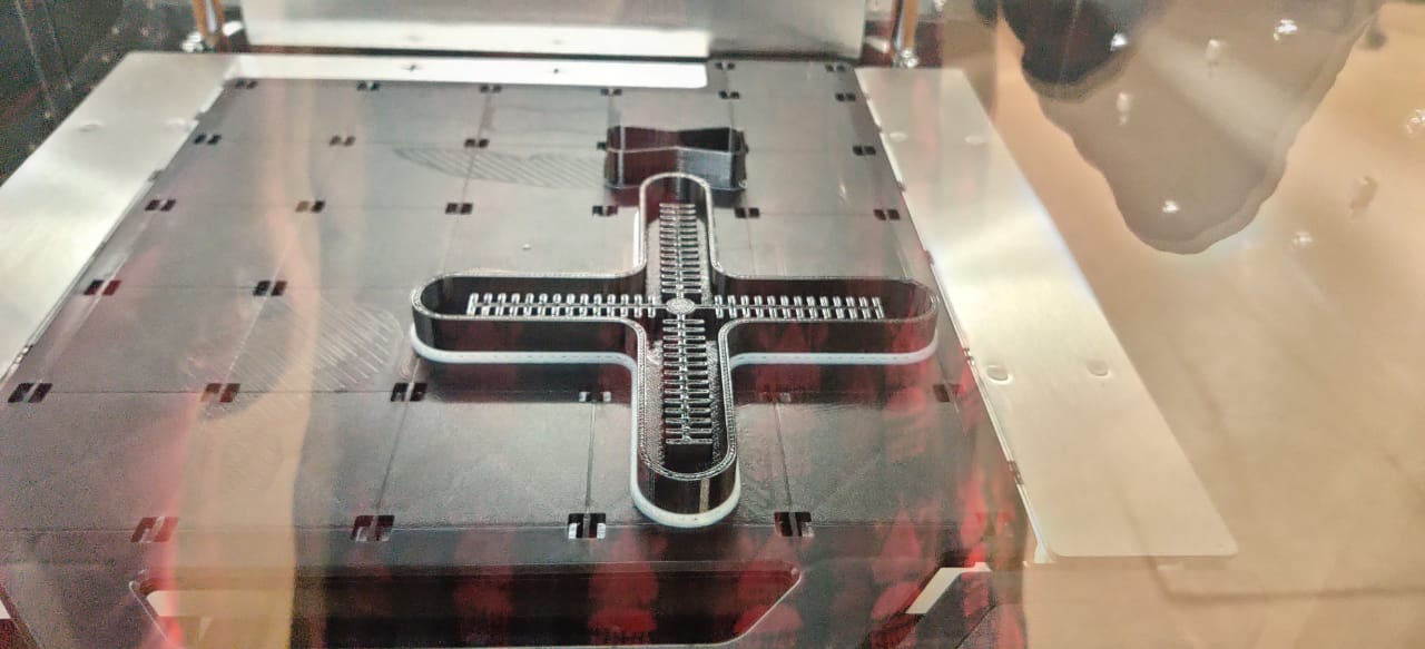
This is the Chanellised part of soft gripper and I put it on print on F-370 3D Printer.

This part come out like this and one part of mould is ready now.
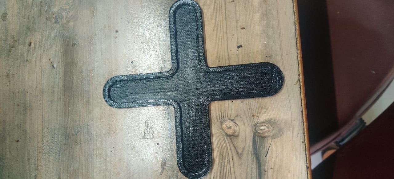
Second Part of mould is also ready. I Printed this part also on F-370
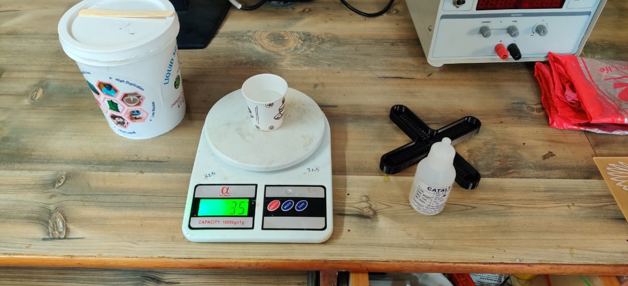
Now its time to make soft gripper with Liquid Silicon Rubber.So I used same process as Molding and Casting Week
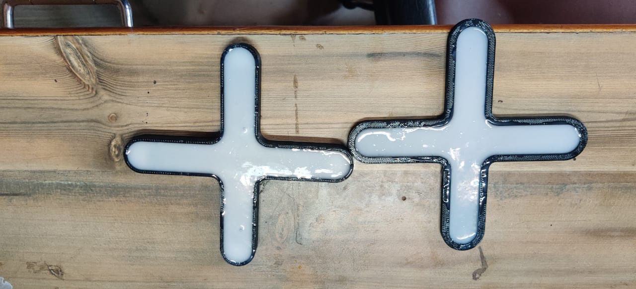
Here you can see I filled both the mold with silicon Rubber.
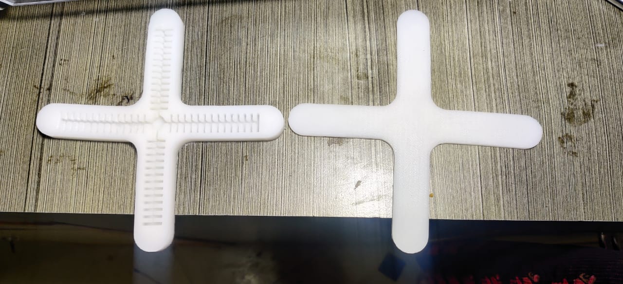
Left the gripper for 4-5 hours and they are ready now.
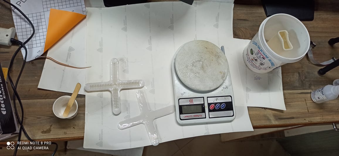
Again I have to stick it together with silicon rubber and I took small amount of it ie 5gm and took catalyst 0.15gm and mixed it properly and applied on the edges .
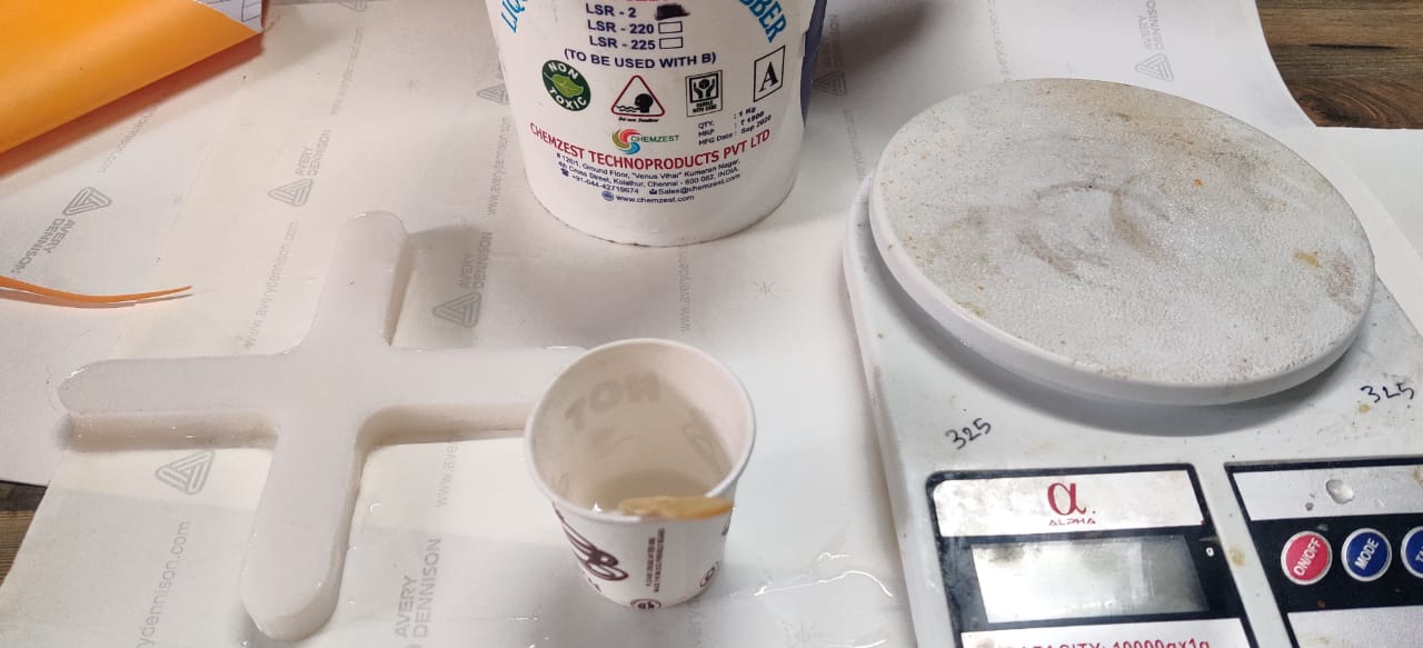
Placed both the part to let it dry
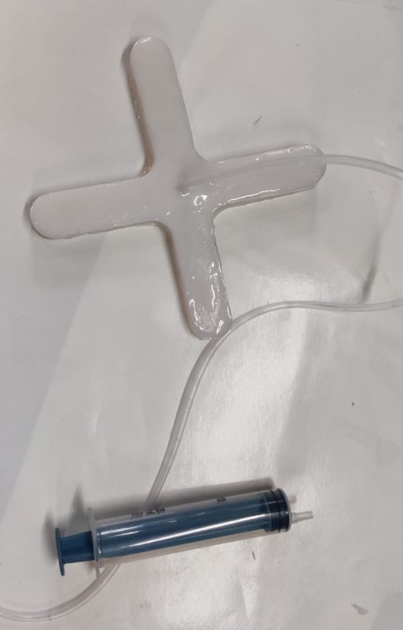
I inserted pipe from top and also used used silicon rubber to fix it.
Second Trial to Inflate
For first trial,As I started to inflate it, There was some leakage from side and again I applied silicon on it and this is the second trial which I recorded and In this process it leaked out from top where pipe is inserted to filled the air. In second attempt it is creating back pressure on pipe and leakage started there.
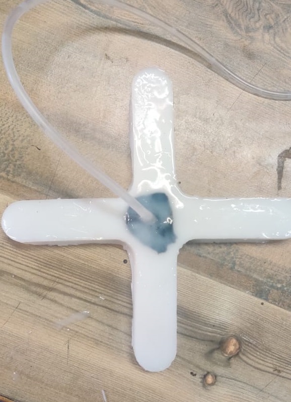
I tried it to seal with mseal and silicon again but still the same leakage happened.
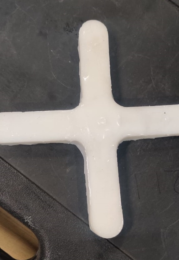
Now I fixed the hole and made another hole by piercing from side and used another pipe to fill air.
This is the attempt made by syringe and this time no leakage.
This is the last attempt I Tried with compressed air and it burst out due to more pressure the adhesion which I made between layers got deattached.
Conclusion
I think the width of silicon taken was more and it must be 1mm so that it can inflate with bare minimum pressure without burst, as well it did not stick properly to withstand that pressure which is required to inflate it as in last video I tried it with compressed air it inflated little bit but burst out as pressure increased.This required optimum pressure and silicon layer must be thin than the top layer I Created ie 3mm as well as base layer should be thin.
Plasma Cutting Machine : Smart Blade Messer Cutting
What is Plasma Cutting
Plasma cutting torches usually use a copper nozzle to constrict the gas stream with the arc flowing through it. That arc jumps from an electrode in the torch to something else – usually the conductive material being cut. That’s a ‘transferred arc’. There are some systems that use a ‘non-transferred’ arc where it jumps from the electrode back to the nozzle, but those are not usually used for cutting. So that means that plasma cutting is only used for materials that are conductive, primarily mild steel, stainless steel, and aluminum. But lots of other metals and alloys are conductive too, such as copper, brass, titanium, monel, inconel, cast iron, etc. The problem is that the melting temperature of some of those metals makes them difficult to cut with a good quality edge.
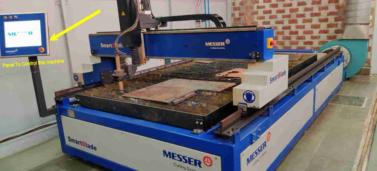
This is the Plasma cutting Machine available in our one of the Centre of Excellence or Skill Development Center.For this week I will work on it.

This is the front and side View of Machine showing dimensions of machine.
Working of this Machine

This is the main control panel of the Machine.Turn on the machine.

This is the backside of Panel and USB will be insert in this slot to give DXF file to cut on Plasma.

This is the HOME screen of Panel.From this drop Down Menu.Click on Home Axis.

After selecting Home Axis option, it will activate two buttons saying X and Y
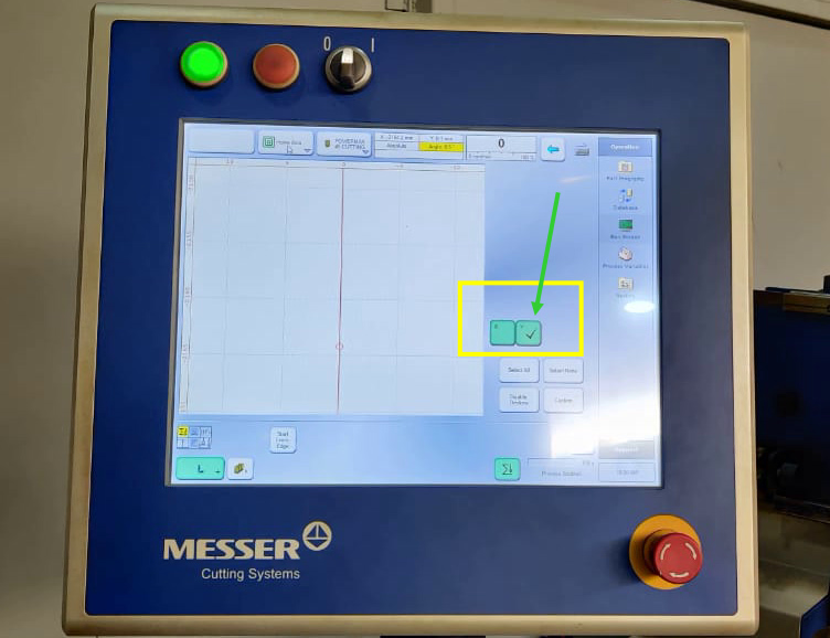
First it will move in Y direction and set the machine at Y=0
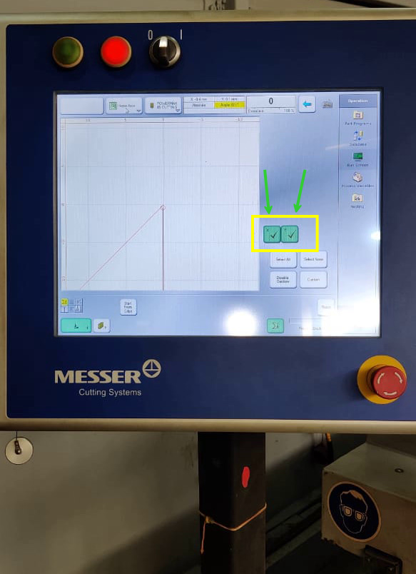
Then it will move in X-directtion and set the machine X=0

After it set to home position we can move it manually with the Manual option in the drop down menu.It will arrows with direction and all you have todo is manually take the head of machine where our sheet is placed on Bed by using touch screen of Panel.Then click on Aligned Plates so that if sheet is placed at some angle it will detect the angle in Y- direction.
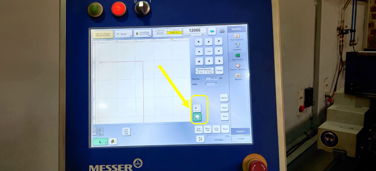
Click on green button showing corner arrow for first point you set.

Then take the nozzle manually behind that point to check the alignment of plate as soon as you set the other point.It shows the angle of alignment of plate.
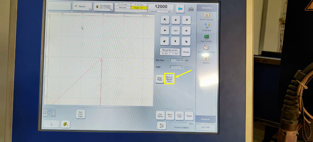
Click on Move to Aligned Plate.Then it comes to starting position of plate.
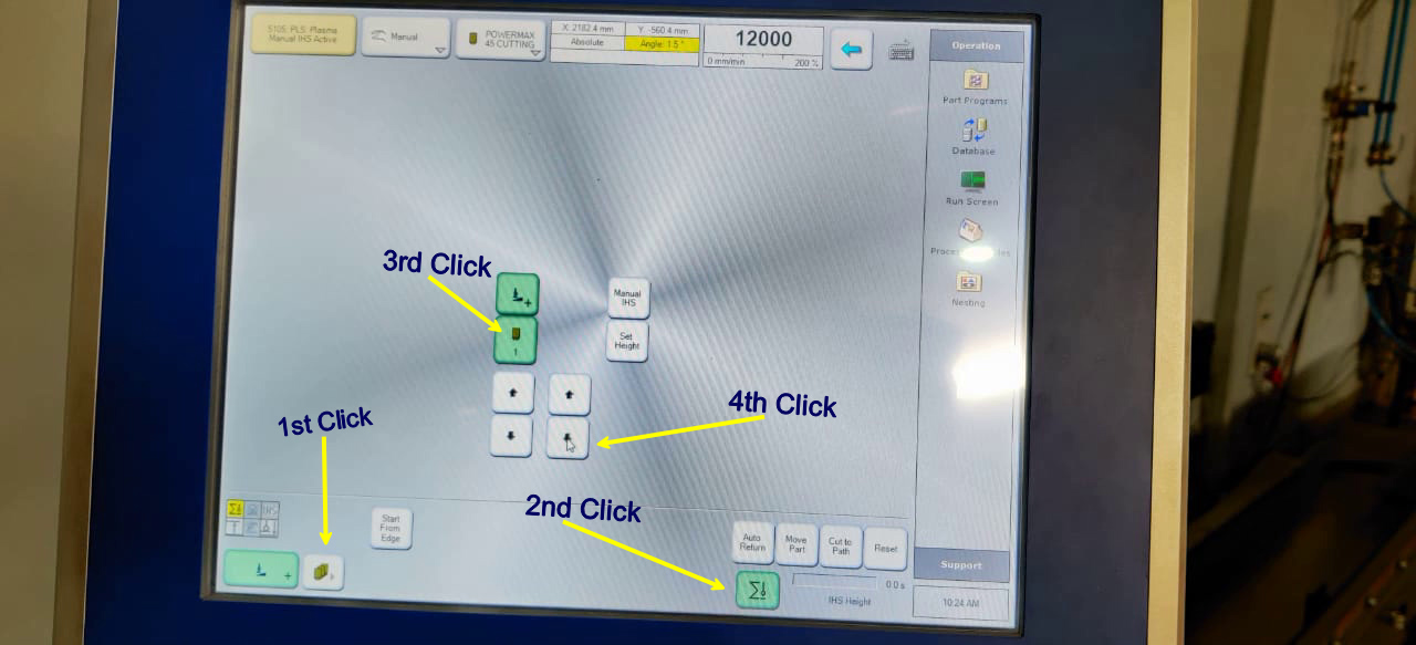
To set the nozzle in Z-direction.Follow the steps shown in image.
Below is the video showing nozzle motion in Z-direction and it touch the sheet and goes 10mm above from sheet.
Then click on Nesting to upload the any DXF file .
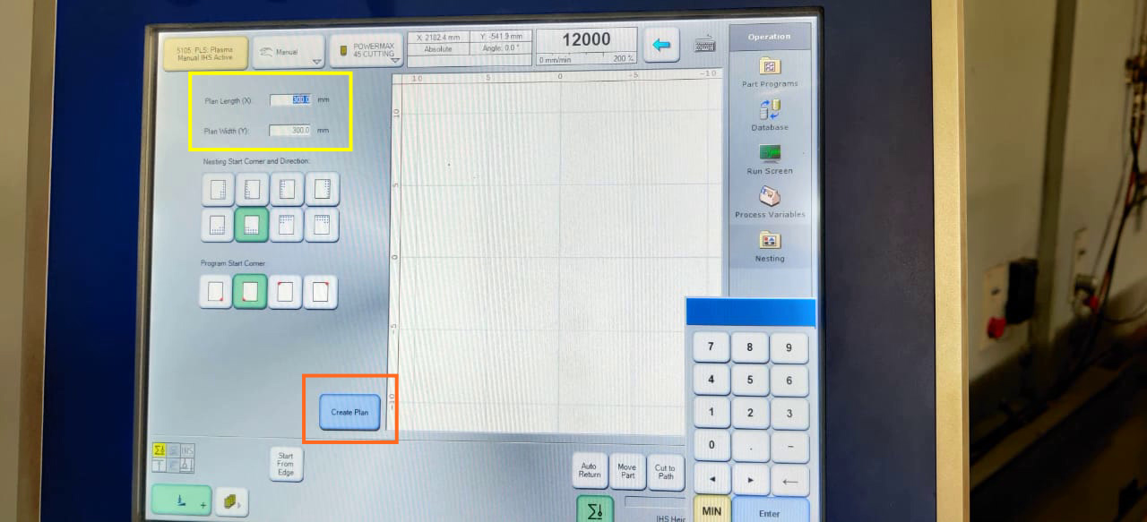
Enter the size of Plate.

Click on Lead In and select quarter circle.Enter the radius of quarter circle.It is essential to give circle at starting point of Drawing.
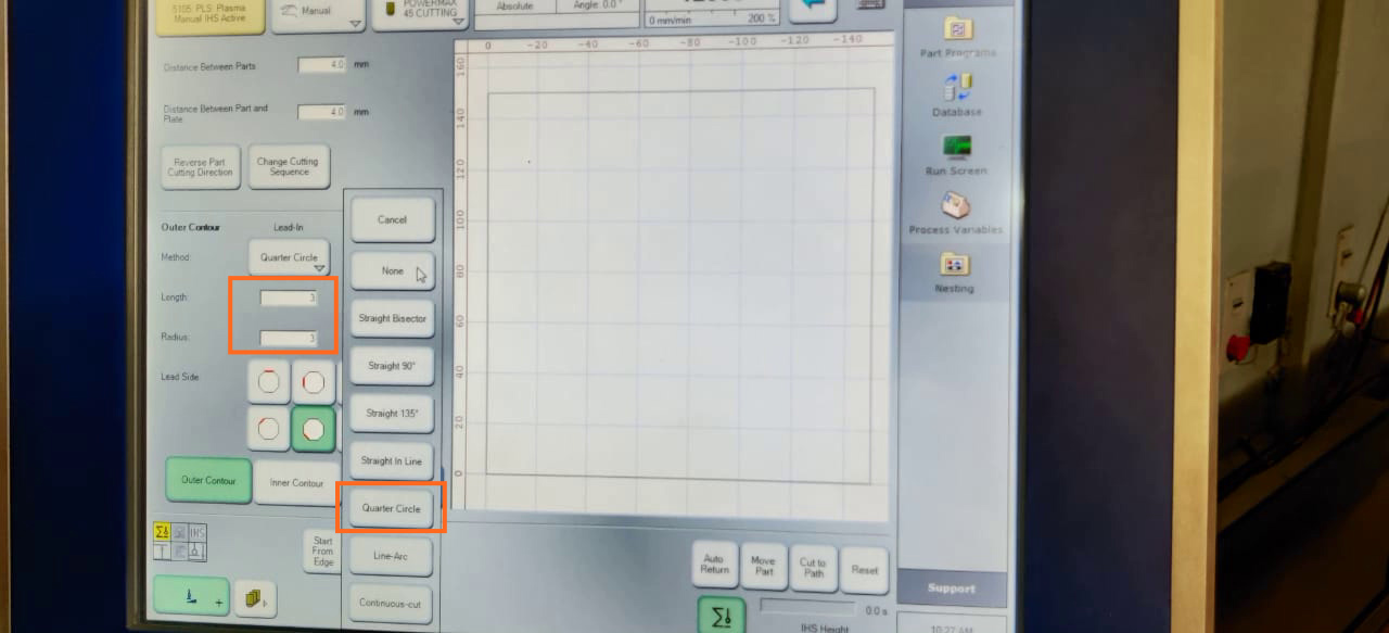
Then in same manner,Click on Lead out and select quarter circle and give radus of circle.

Click on Apply
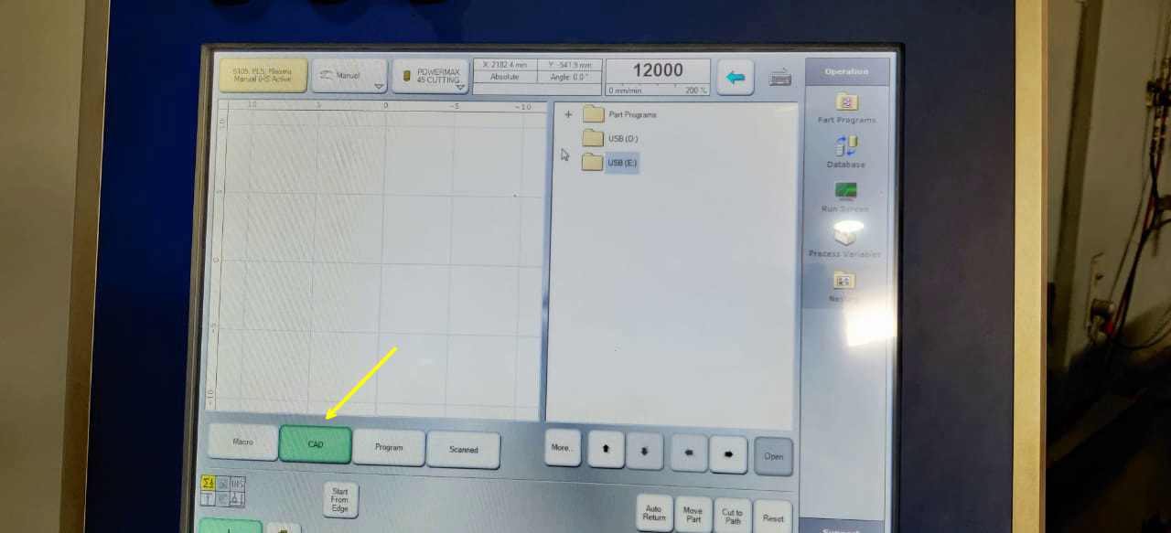
To open File from pendrive .Click on CAD
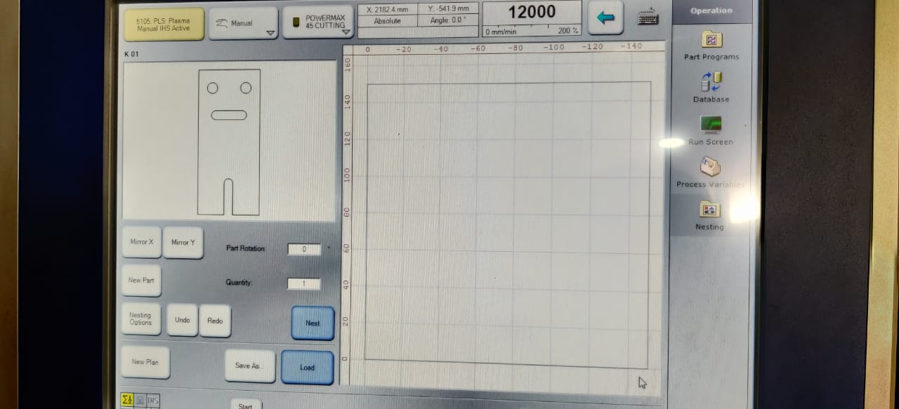
This is the shape which I made on NX.I open dxf file from pendrive.

Click on Nest .It will also create part in array if you want to cut more than one part.

Then Click on Load

After loading,it will ask for plasma cutting parameter.Click on Plasma Cutting.

Select the type of material you are using to cut on Plasma Cutting Machine. I used Mild Steel.

Then select the thickness of sheet.I gave 3mm. Click on Apply.

It will show the tool path as well as G-code for the program to run on Plasma.
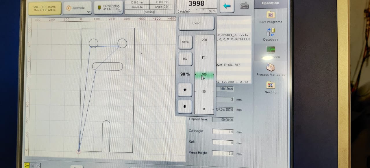
We can set the speed of Nozzle.
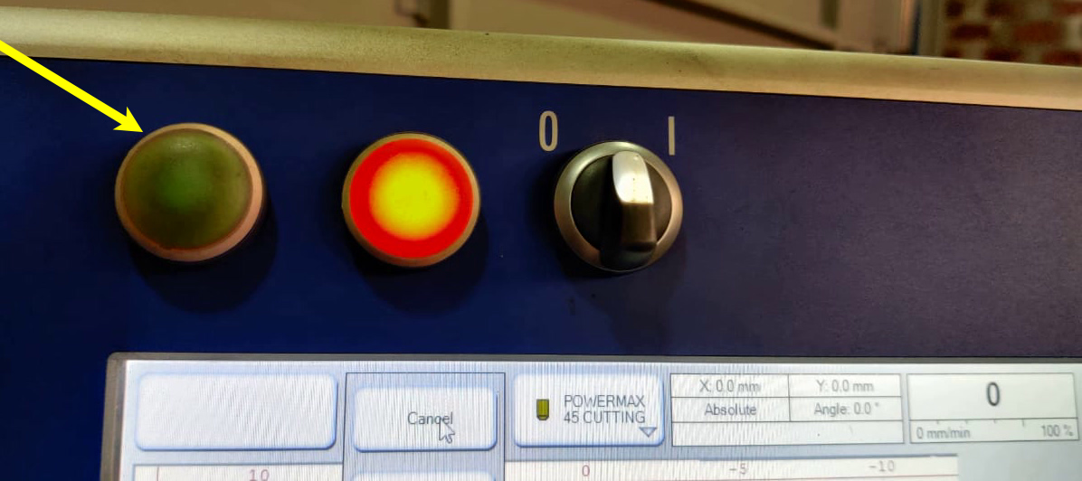
Press this to Run the machine.
Dry Run
Before Final run, we can also dry run machine to check the tool path.
Final CUT
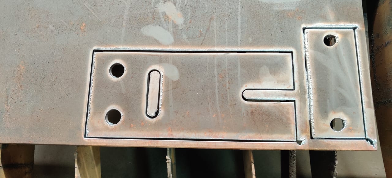
TED come out like this after cutting.
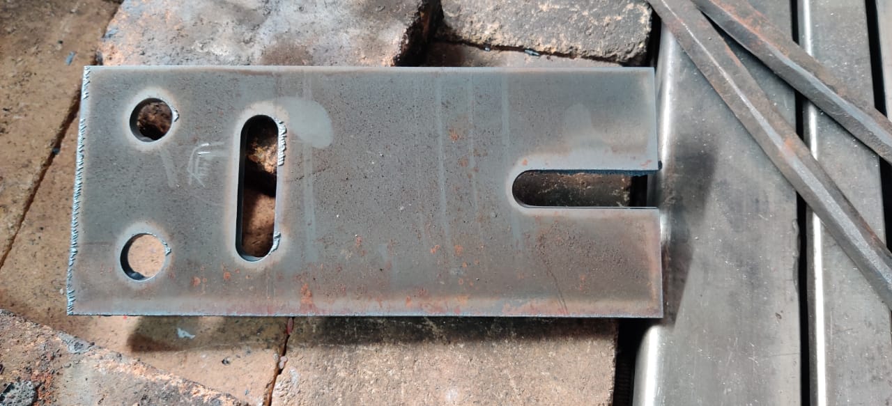
Dont touch it before half an hour it absorb much heat and you can also see BURR on face occcur due to melting of metal.I used tongs to remove it from sheet.
Design of TED
I have designed the part file of TED on NX-11.

I used sketch and with lines and circle .I made it.

Then expoted it in DXF format.
Failed Attempt
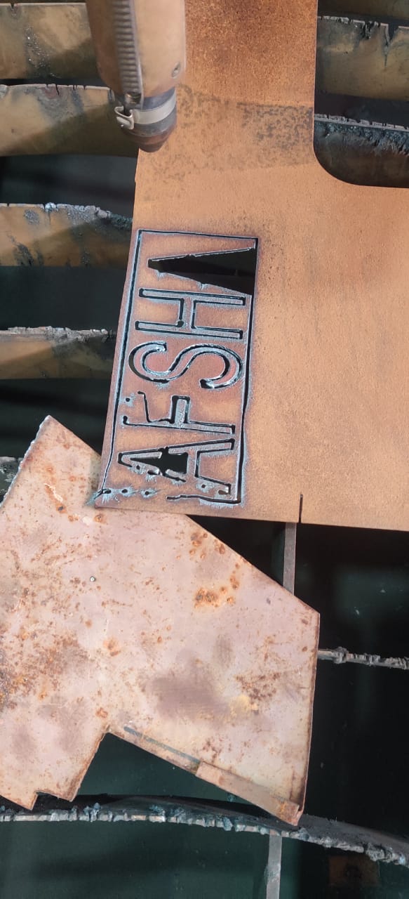
In this case, the thickness of sheet is very less and it was full of rust,the sheet was also bent.
The Name which I designed on NX-11 have width of letter approximately 3-4mm and it cut the whole material out of there. The kerf of this machines is 1.5mm and in two passes of nozzle it melted out whole material.Thats why it failed
In this video you can see that it stop at one point as sheet was bend at that place.There it was handed manually.It didnt cut the part in one go.
Group Work
Test Cut 1

This test was done to check the contour test on this design.For this we choose none for lead in and out thats why the circles didnt come out.
Test Cut 2

This test piece has been cut with contour in and out setting and it comes out fine.
Test Cut 3

The most important term here is lead in and lead out,It shows that tool will come with a curve on contour and also left the contour with curve as I have already shown above. I took quarter circle and it created U shape shown in image so that the desired part not get distorted.

Here you can see the red lines that is tool path created by machine software on outer contour and on inner contour.
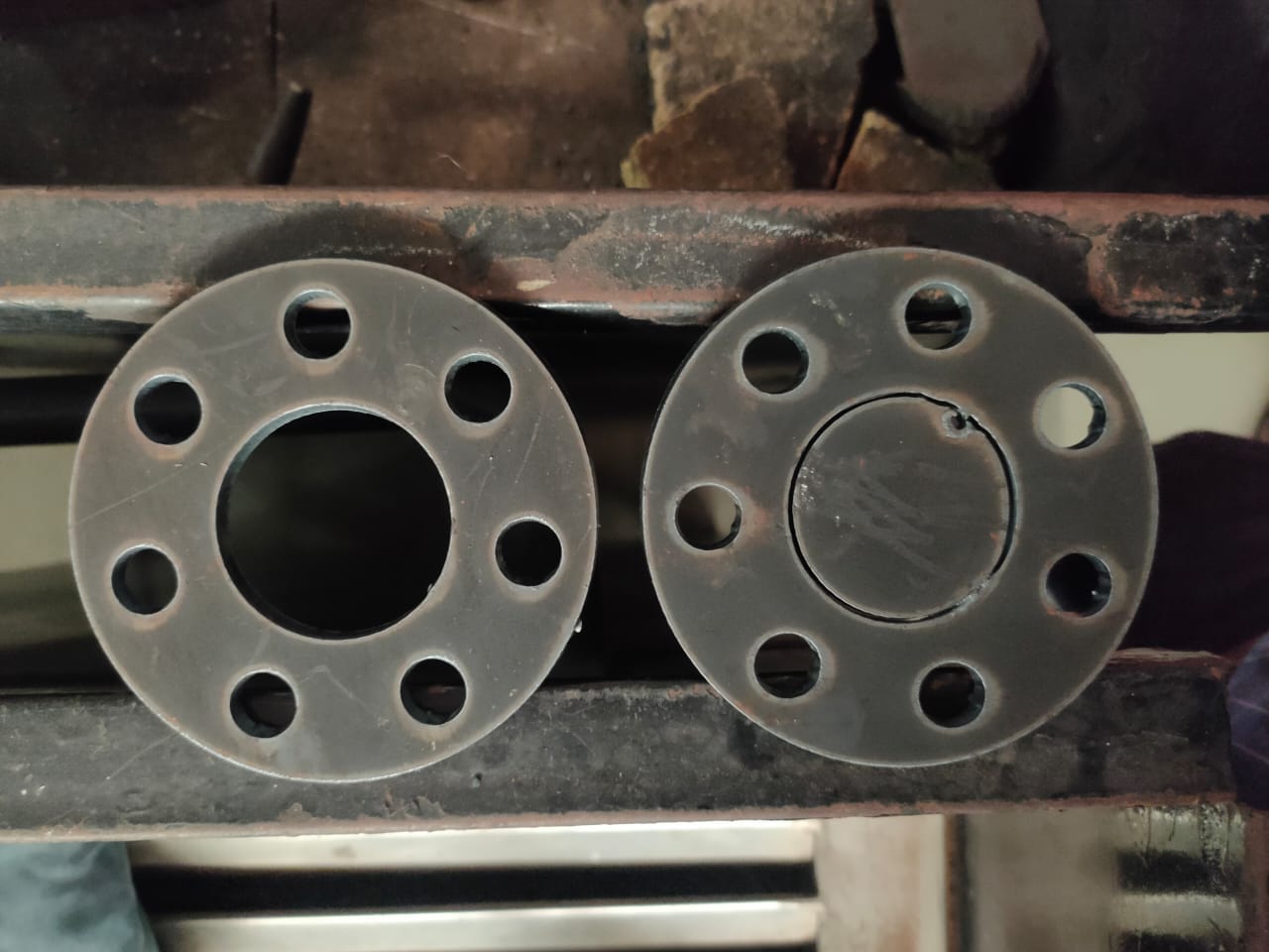
These are the perfect cut done by machine after the nozzle has been changed.
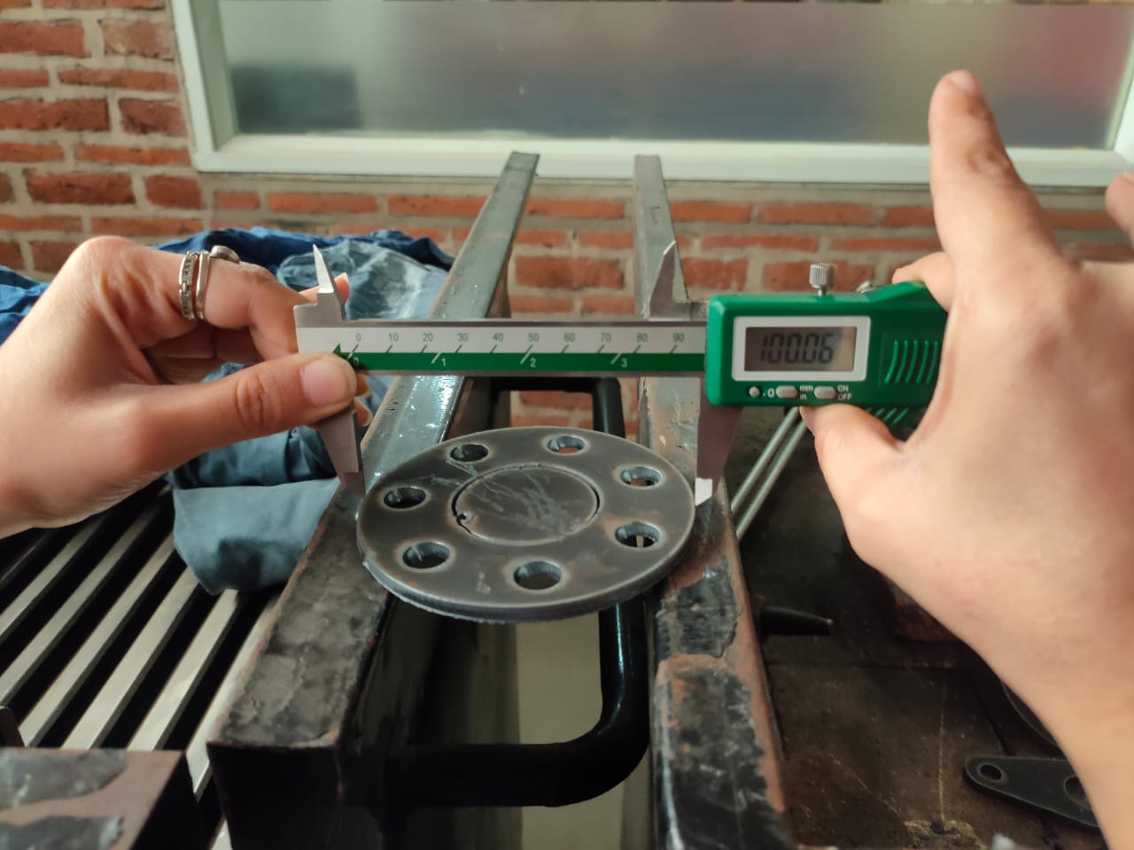
I measured the dimension,as outer dimension was 100mm and on the outer edge of topmost part it shows error of 6 micron.
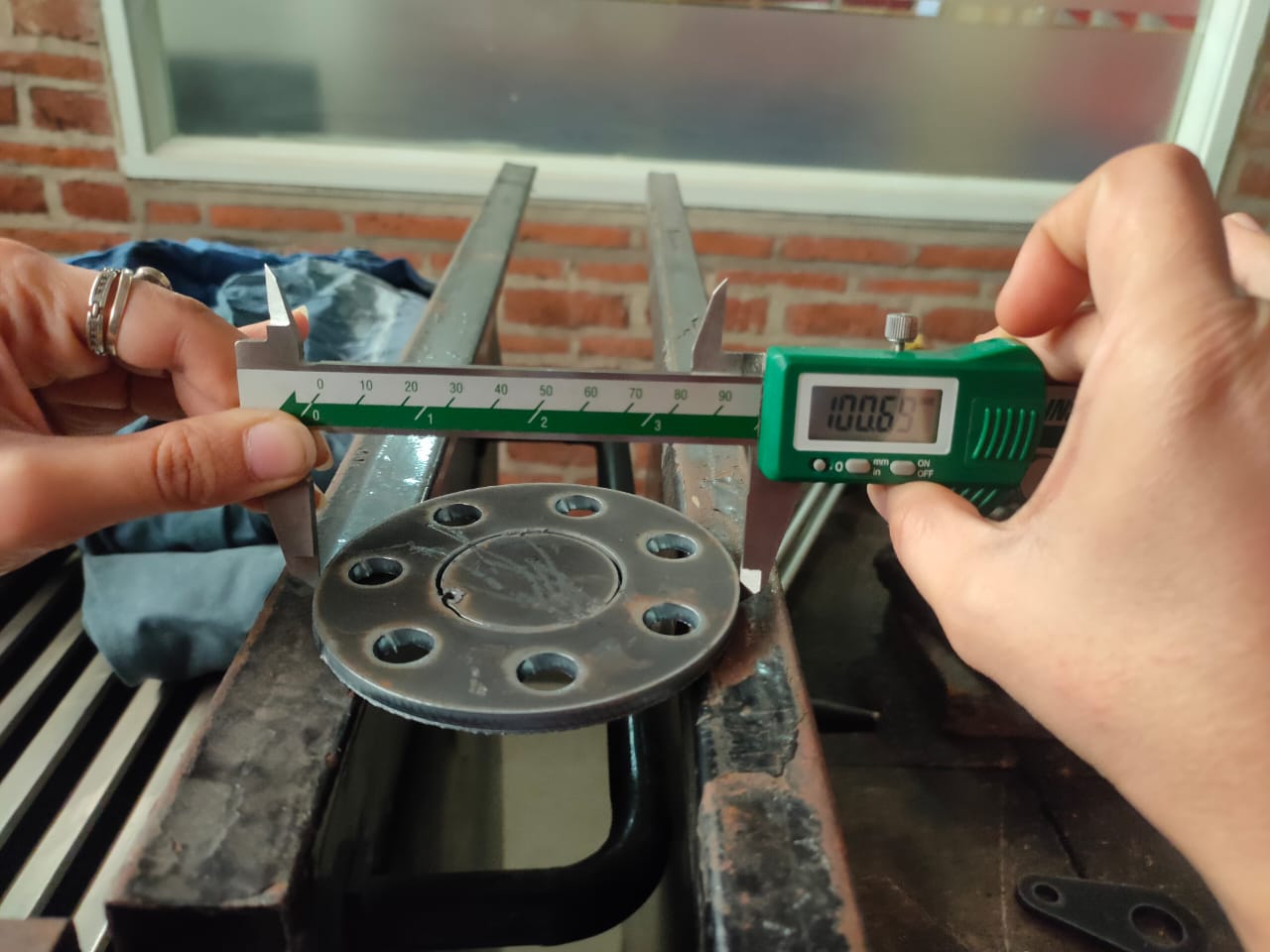
As I measured it from bottom, It comes out 70 mm.There is some tapering occur while cutting due to that this error comes.
Conclusion
This machine works well when the material is free from rust and clean.Also there is no design consideration we need to take,as 0.2% error came due to nozzle and material misalignment.
