3D Scanning and Prinitng
In this week,I have performed following assignment.
>Testing the design rules of the 3D printer as a group project.>3D Print an object that cannot be made subtractively.
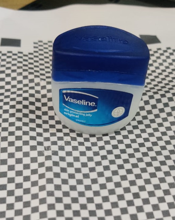
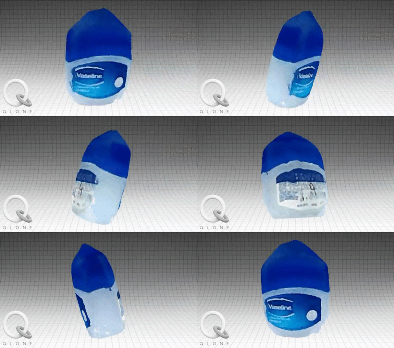
>3D Scan an object (and optionally print it).
3D Printing
3D printing is also known as Additive Manufacturing where successive layers of a material are deposited on top of one another to create a 3D model with the help of G-codes Which are obtained by slicing of STL file of any Object 3D Model through Slicing Software.
3D Printers in Lab
1. MAKERBOT REPLICATROR Z18
To ensure easy, accessible 3D printing, the MakerBot Replicator+ comes with the Smart Extruder+ and all the standard features of its predecessor. The material is non toxic and easy to print with minimal warping. The specification of Makerbot Replicator Z18 are as follows:Print Technology:Fused Deposition Modeling.
Build Volume :{30.0 L X 30.5 W X 45.7 H CM}{11.8 L X 12.0 W X 18.0 H IN}{2.549 cubic inches}.
Filament Diameter : 1.75 mm
Filament Compatibility : Makerbot PLA Filament [Large Spool]
Nozzle Dia: 0.4 mm
Software which is used for slicing is MakerBot Print Software
2. Ultimaker 2.0
Print technology: Fused Filament FabricationBuild volume :223 mm / 223 mm / 205 mm
Layer resolution Fast: 200 micron (0.2 mm)
Normal: 100 micron (0.1 mm)
High: 60 micron (0.06 mm)
Ulti: 40 micron (0.04 mm)
Positioning precision 12.5 micron / 12.5 micron / 5 micron
Filament diameter : 2.85 mm
Nozzle diameter : 0.4 mm
Print speed : 30 mm/s - 300 mm/s
Travel speed : 30 mm/s - 350 mm/s
Software which is used for slicing is Cura Software
GROUP ASSIGNMENT
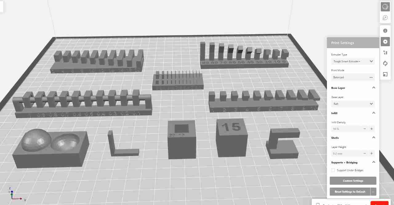
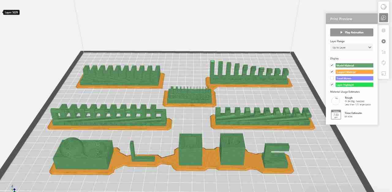
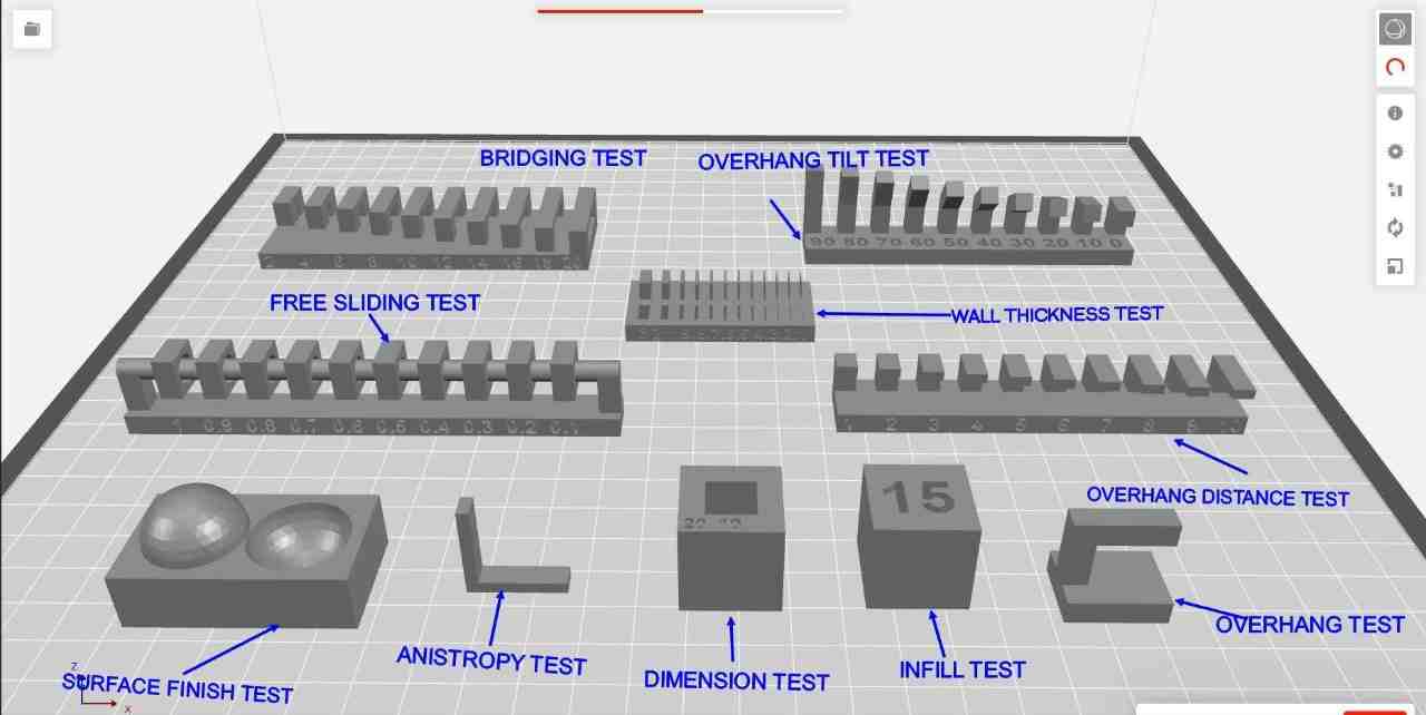
In group assignment we decide to print the STL files from Fabacademy.For this we used Makerbot Replicator Z-18 3D Printer.
The settings are:
1. All the parts are printed without any support.
2.Infill:10%
3.Layer Height:0.2mm
4.Raft :On
5.Material Used:Tough PLA(Slate Grey)


This is the 3D Printer which we used for group assignment.First we have to give power supply to it.

After Power ON the printer, there is a wheel which we have to rotate to go through different option.

There is command showing directly to give print to it by pressing the wheel.
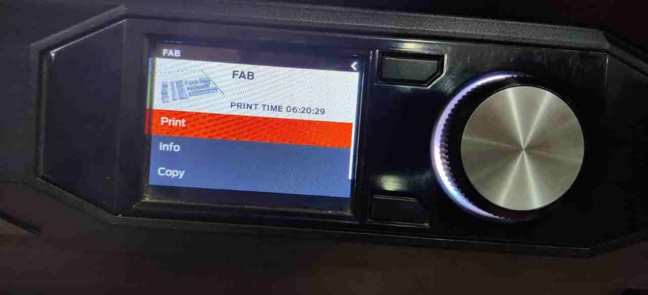
When we press print there is option to give print through USB or internal Storage.
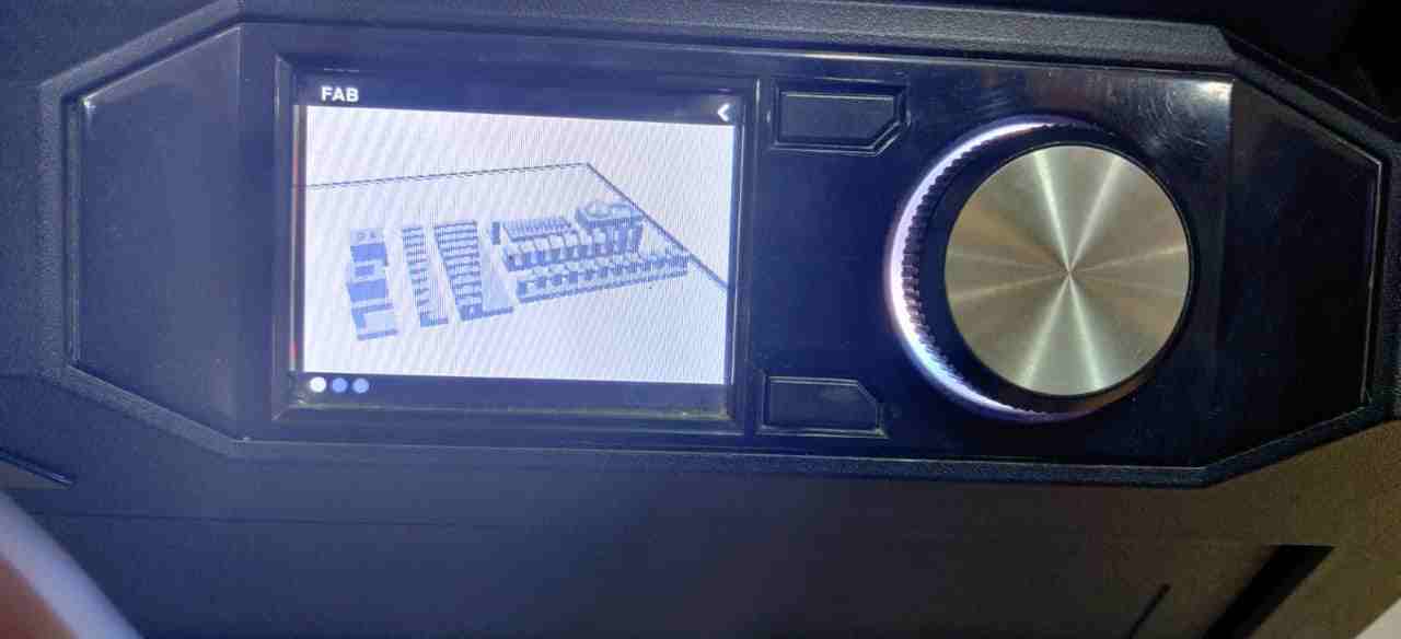
We choose USB as we save the makerbot print format file to give print.
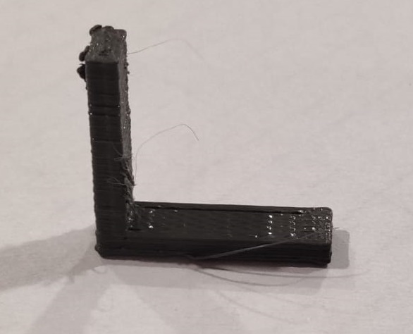
This is the L section which comes fine
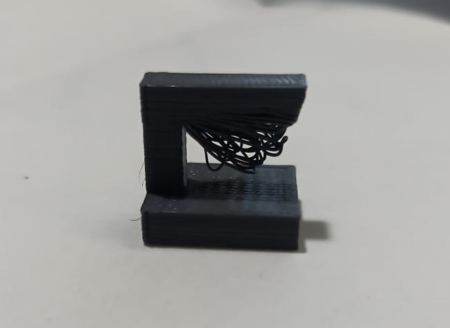
This is the L section with different orientation.In this the material chipped off as there was no support for overhang section.
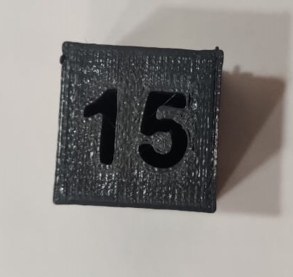
This block shows box showing infill test.
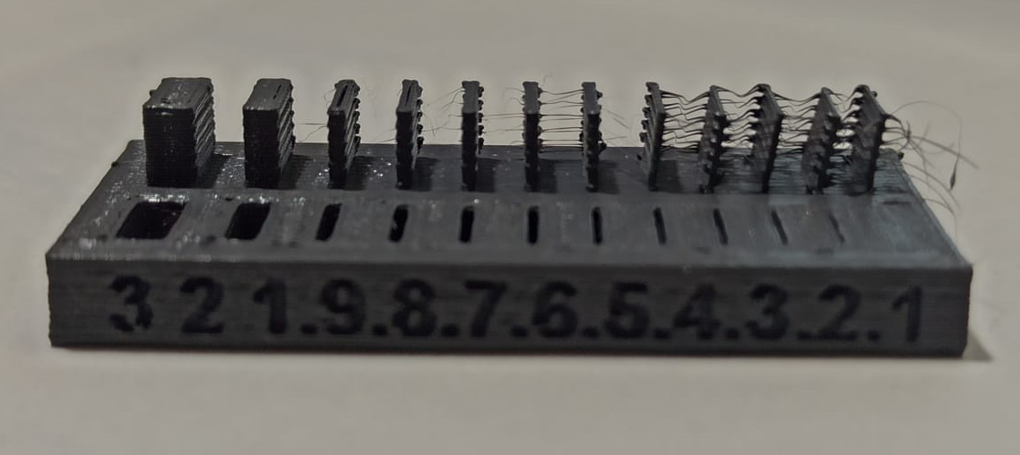
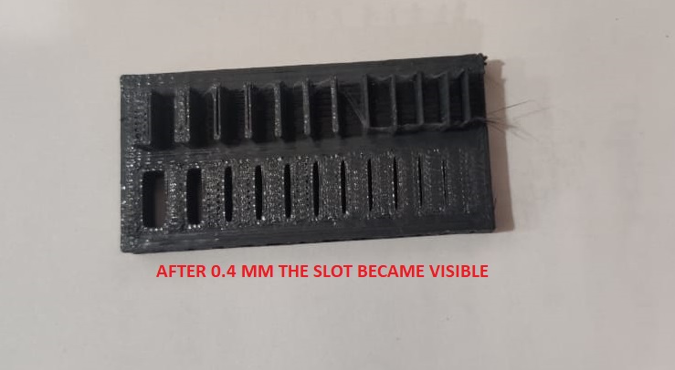
In this test we are able to find that for particular wall thickness,the slots are of particular dimensions or not. The slots are visible after 0.4 mm thcikness.
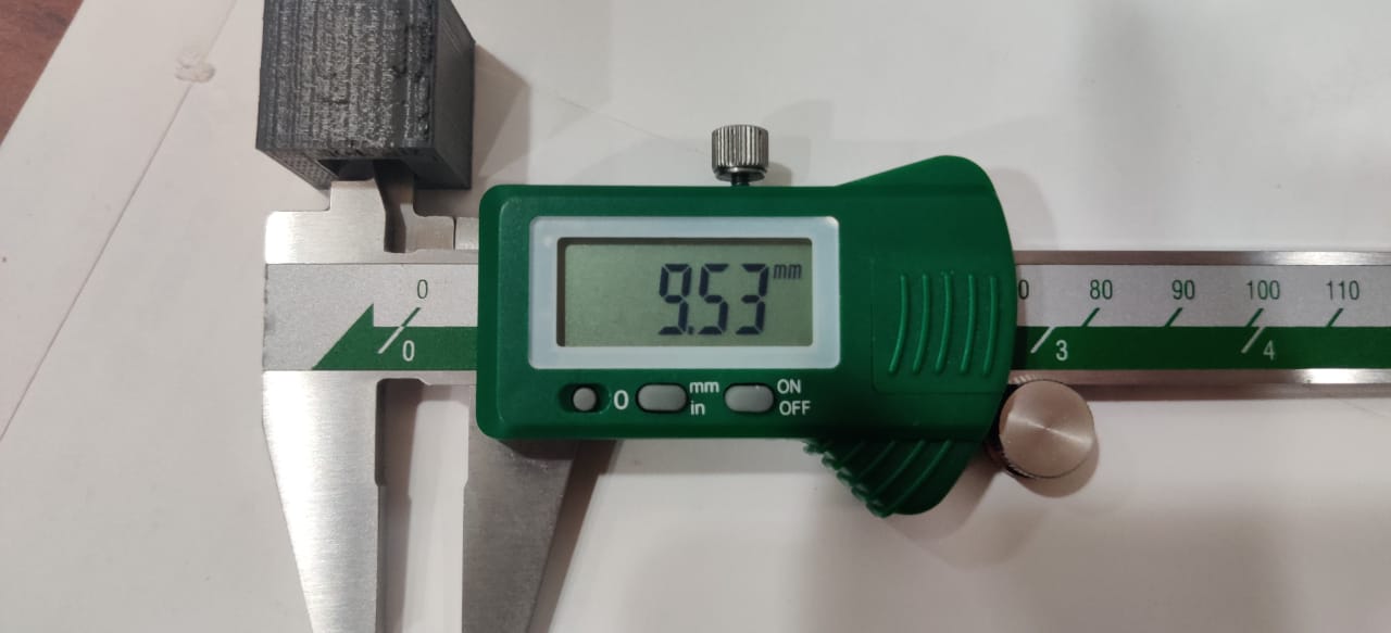
The block had internal cavity of 10mm which after printing comes out to be 9.53mm which is 0.47mm less than the actual size.
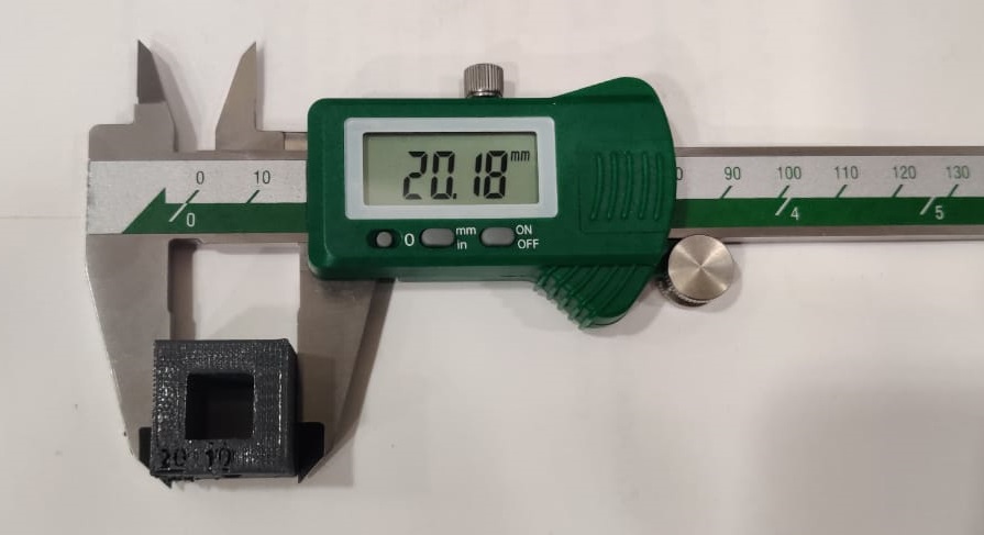
This is the cube which was printed on Makebot.For this I found the size of cube icreases by 0.18mm.
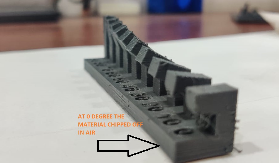
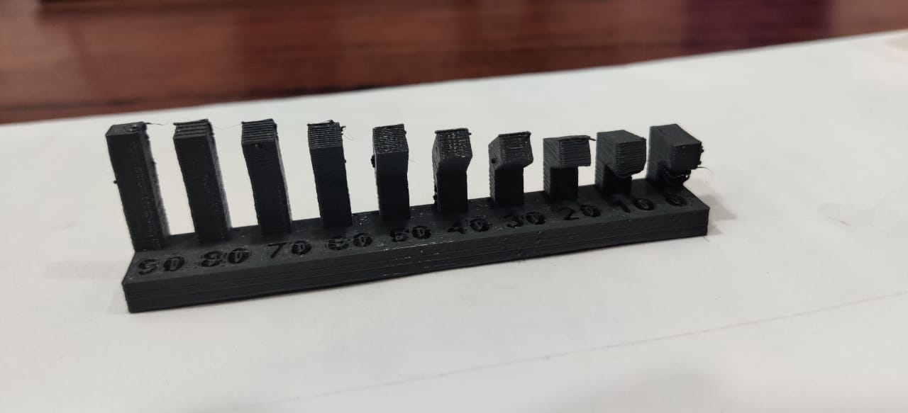
At straight L section at 90 degree was printed good and at angle of Zero degree, it started hanging.
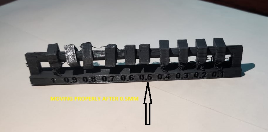
This image is showing that the hole clearance at which block started moving on shaft is 0.5mm before that upto 0.4 mm it is fix.

Upto 10 mm of overhang of section, the material chipped off from surface
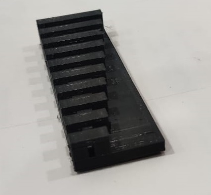
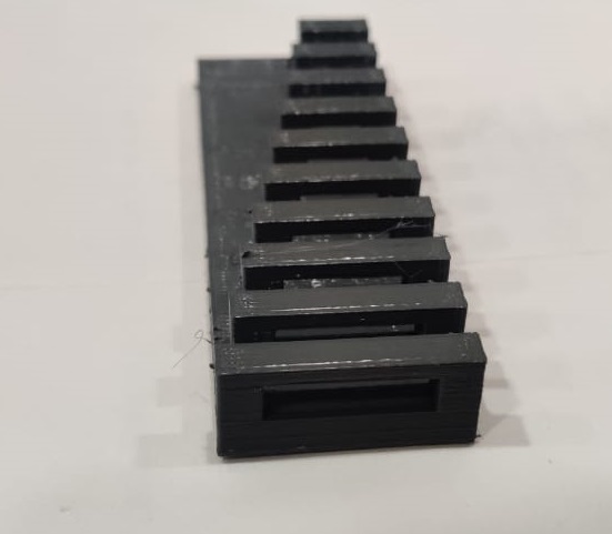
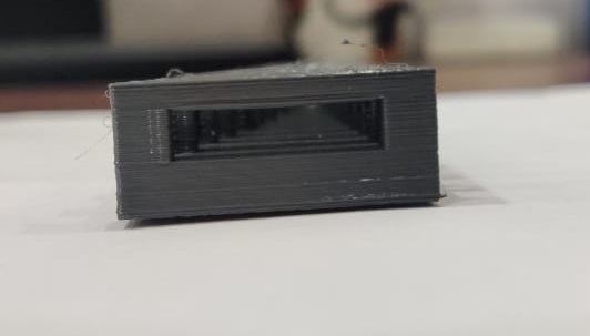
It is showing Bridging test which comes out to be perfectly fine. Bridging is when printer prints a flat,horizontal part of the model mid air.
All files are given on Neils page. Files Can be downloaded from
INDIVIDUAL ASSIGNMENT
In individual assignment I dicided to make Earing.So,I made 3D Printed nested earing on Makerbot.

First i made sketch of one the ring for nested earing ,i draw Eclipse of 15 mm major dia and 10mm minor dia and guide is semicircle.

In which i used swept command

Then i used mirror feature to mirror it and made a cuboidal block at one of its end.

Then the other ring of smaller size is made with one hole.

After I used assembly to assemble all the components.

In assembly, by using add component,i added one by one component.

Through align constraint i ailgned all the axis of the cylidrical holes and Move command is used to move one part to translate in three direction and rotate it in three axis.

This is the wireframe model.

This is the assembly with some rendereing.
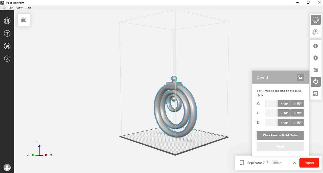
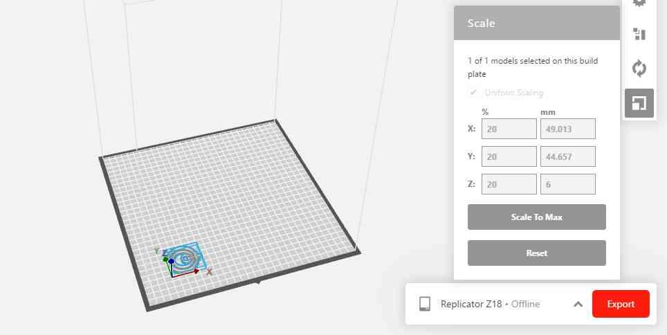
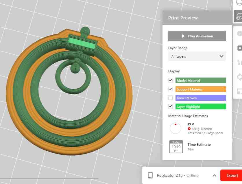
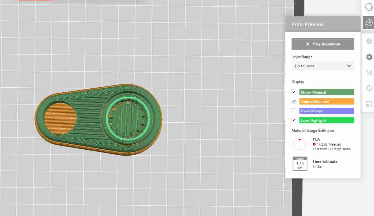
In makebot print First I imported file as STL assembly file. After that i do rescaling to 20% and Orientation is important for optimizing the print.


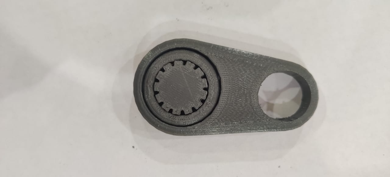
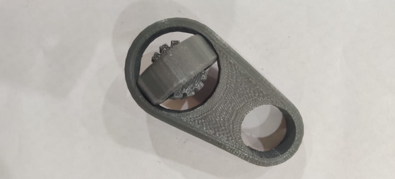
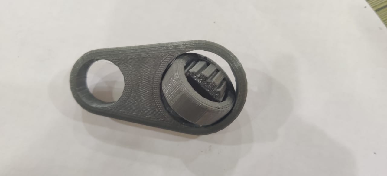
These images are showing the 3d printed part of assembly.
Setting for this print
1. Layer Height : 0.2 mm
2. Raft type : Brim
3. Infill : 10%
4. Material Used : Tough PLA
5. Printing Time : 18 min
6. Support : off
Failure
After my first print on Earing,I saw that for raft setting,it sticks on the raft and did not remove Properly


These images showing the raft and the failed part.


