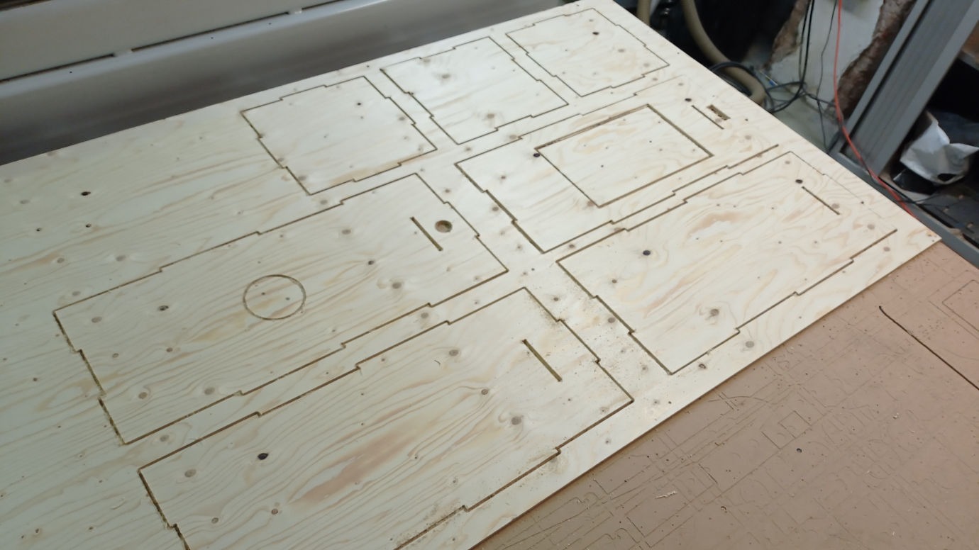
For this week assignment, we had to make something big on wood, using the CNC. For this it was required to have Dog Bone Joints, since the CNC drill cuts a little bit rounded, so it doesn't makes straight cuts, so that makes this difficult to fit.
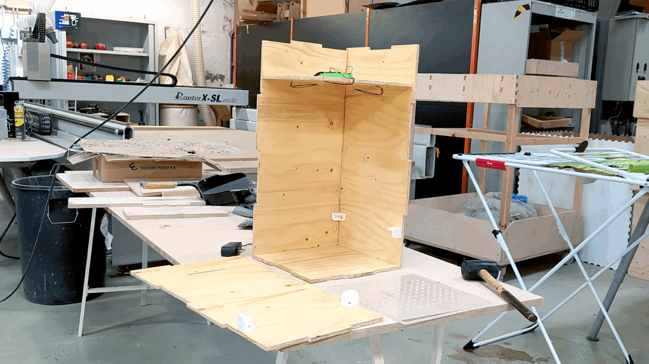
In the beginning (during lockdown) I designed a table and stool... but was never able to CNC it because of Covid. So when we went back to the lab, I has already designed the box of my project POWAR, and that was the one I finally cut on the CNC.
CNC stands for Computer Numeric Control,
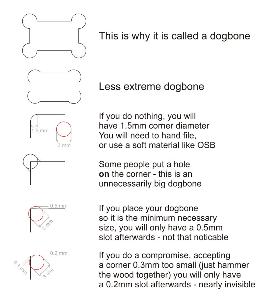
The Dog Bone joints, are called like that because they look like a dog bone, and the need of this in the design is because the CNC tool is rounded and not squared, so it will never reach a corner completely if not adjusted for that, so that will give you a bit of trouble if you are going to fit two pieces together because... they wont fit correctly.
I found a very nice explanation about how to make Dog Bone Joints manually that I will share below.
Basically what I did was to create a cylinder with the diameter of the tool, and snap one of the borders to the corner of the object I'm cutting and then extrude it.
As it says here, you should also snap the center of the cylinder to the corner, but that will create a bigger unnecessary joint, compared to the smaller one I'm telling you which is much cleaner in the design.
After creating the cylinder, you can also mirror it to do exactly the same cut in the other side.
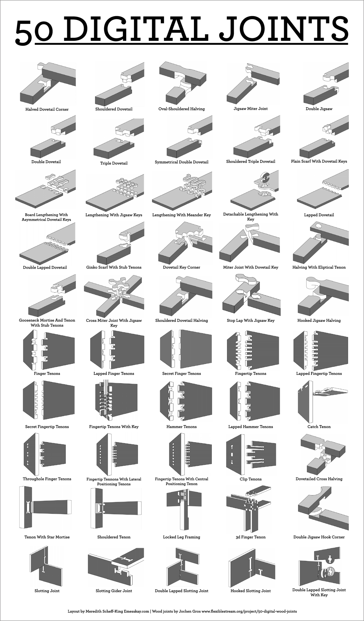
There are a lot more kind of press-fit joints, like doing them on top or in the side, but this are the ones I used.
*After I learned this I discovered that there was a plug-in in Fusion 360, that is basically a python code that does these joints for you. It kind of does the work, but it is not that good in the end. I will leave the link to the documentation and a youtube tutorial of how to use it in here.
http://tapnair.github.io/Dogbone/
Youtube Tutorial
For this project I followed a tutorial to create a stove in Fusion 360 and modified a little bit the measures and design, and then applied the learnings from the tutorial, to create my own desk with a Z shape on it because of my last name. As I was saying in the beginning, I never cut this one because of Covid, but instead, I cut the Box of my final project POWAR.
In the same tutorial of the stove, they also teach how to do the dog-bones in an easy way.
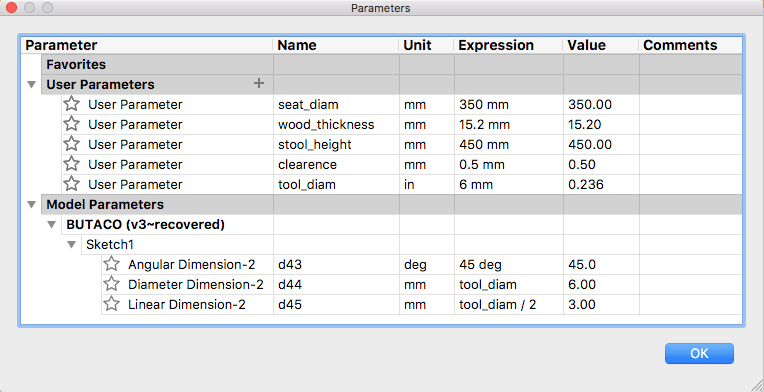
One of the most interesting things I learned in this tutorial is how to use parameters in my design to control different things like the thickness of the wood, the diameter of the tool (drill) I'm using in the CNC, the clearance I want to have in the cut, or even also some characteristics from the object like the height, diameter or some angles.
This helps a lot to make quick changes without having to redesign everything again, but instead just changing a parameter.
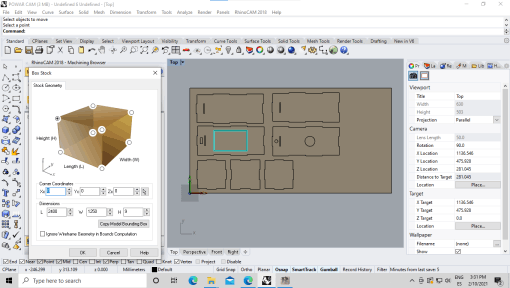
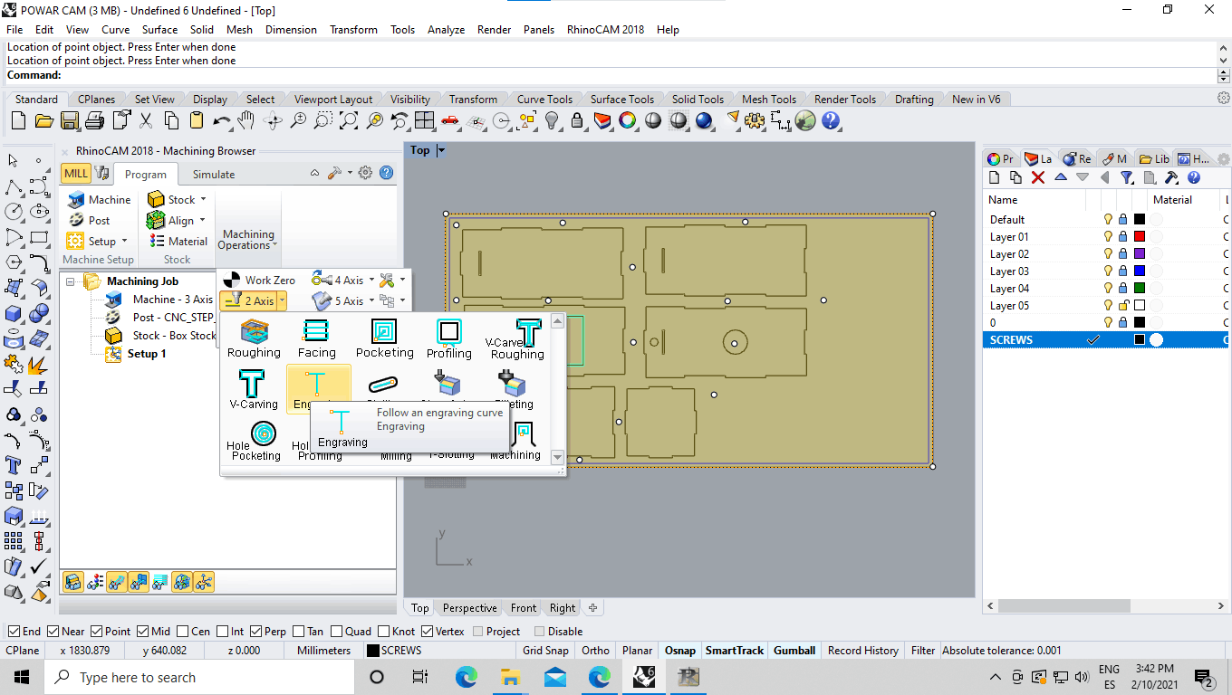
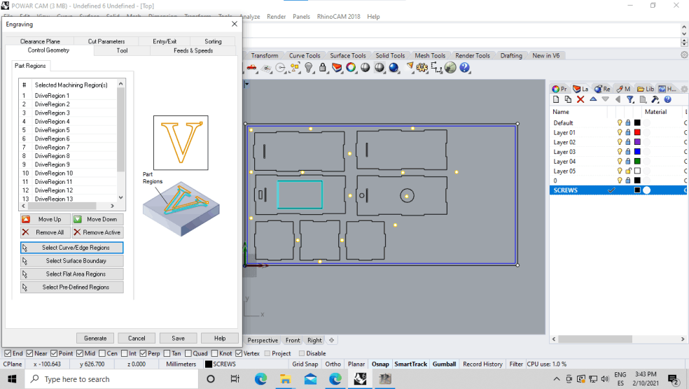
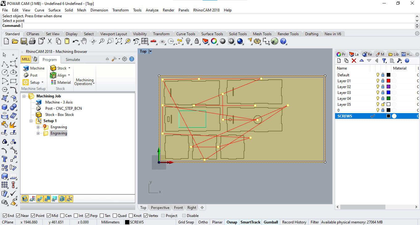
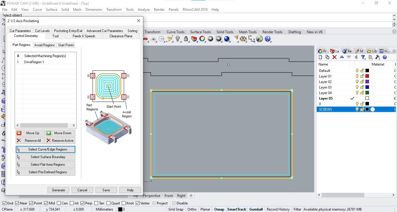
1 - Press: "select curves or edge regions".
2 - Choose the geometries you want to cut from the file preview.
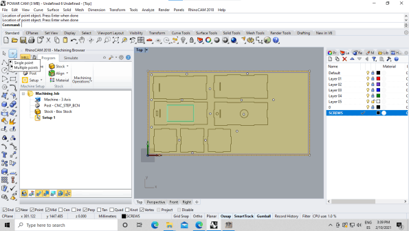
3 - Select the Screws Layer in the right.
4 - Select all screws.
5 - SAVE
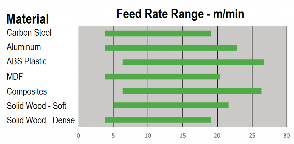
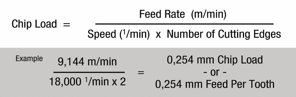
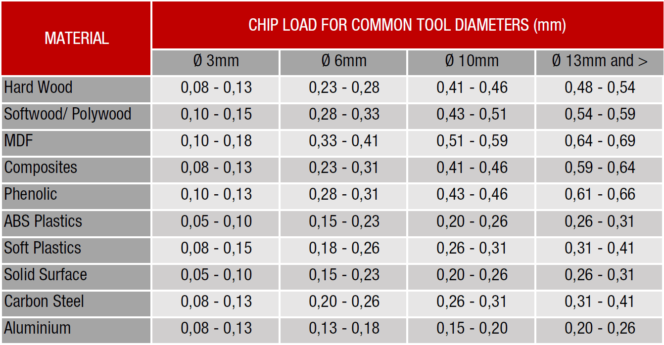
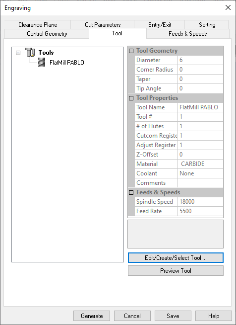
This are the settings I used, keeping in mind the equation, the material and the tool to create my tool on the software. measured with a caliper the tool to get some info from it.
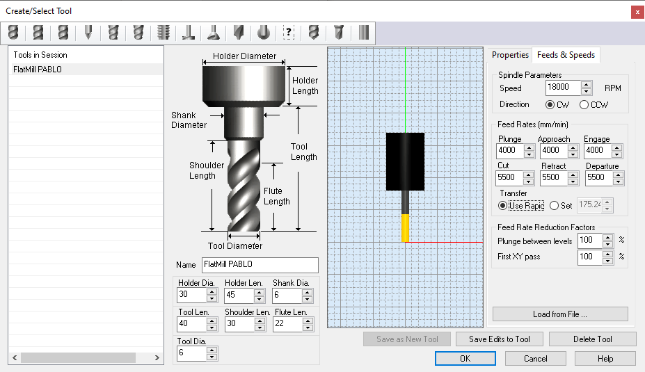
Tool diameter: 6mm.
Press: Create / Select tool
1 - TOOL always turns right.
2 - HOLDERS: Is the piece inside the machine holding the drill. The values are taken from the machine.
3 - TOOL LENGHT is the part of the tool that is outside the holder.
4 - SHOULDER y FLUTE the part that cuts from the tool.
This is the same tab that we have seen before.
(LOAD TOOL)
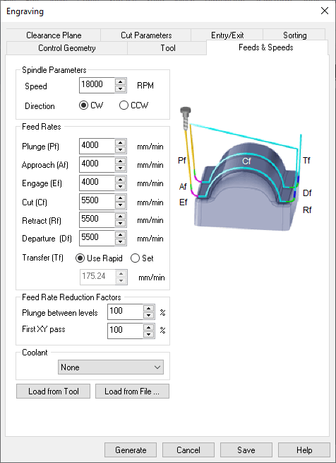
This is the flight speed when you are not cutting, so you don't hit anything.
CLEARANCE PLAIN DEFINITION:
- Stock max z + distance (20mm).
CUT TRANSFER METHOD:
- clearance plane.

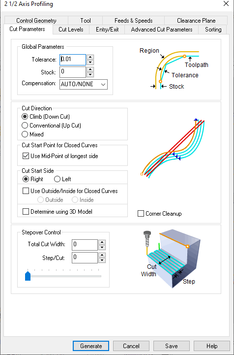
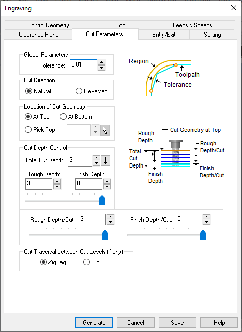
Tolerance:
0.01 (lower the value, it is more exact)
Cut Direction:
Natural
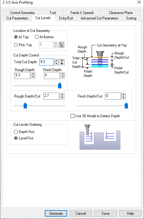
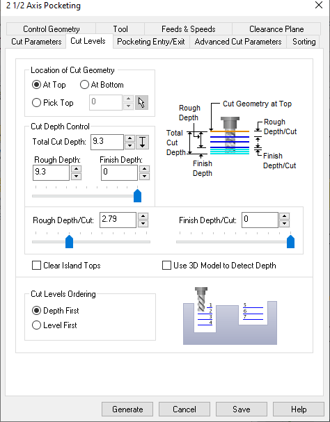
Location of Cut Geometry:
At top.
Cut depth tool:
3mm approx for screws.
Rough and Finish:
This is a configuration where you decide if you want the first ones to be ROUGH and the last layers more detailed… in this case everything is rough.
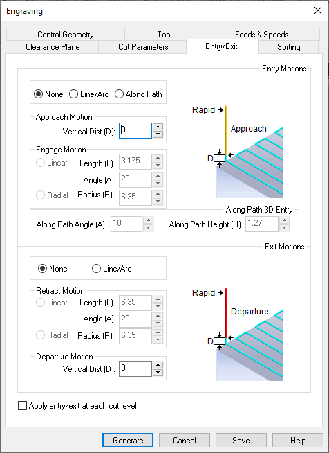
It's the way you enter the material: Enter straight and first cut, or enter cutting as in 3D ... (parabola).
At the moment we leave NONE in the two options because we want it to go straight.
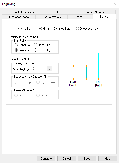
The way you organize your cuts, to take as little time as possible. (minimum distance sort)
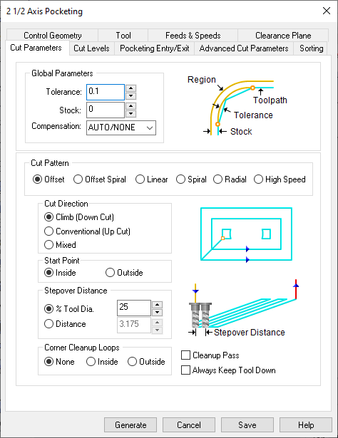
GLOBAL PARAMETERS:
Tolerance I leave it the same.
The Stock I lower it to 0 (it's the offset distance between the lines and the tool)
CUT PATTERN:
The way you remove the material (from the inside, linear, zigzag, etc) OFFSET works very well.
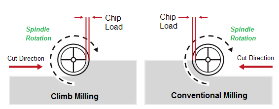
CUT DIRECTION:
Climb (because the tool is downcut)
START POINT:
Whether it starts from inside or outside the line.
STEPOVER DISTANCE:
How much the tool is mounted on the previous cut (how much percentage of material it eats in each cut). Overlapping.
CORNER CLEANUP:
In case you want me to clean the corners. Not in this case.
Total Cut depth:
5mm which is the size of my acrylic.
ROUGHT DEPTH CUT:
How much it cuts in each cut. The maximum can be 3mm (half the diameter of the tool)… let's give it 2.5, which is half the depth we want.
CUT LEVEL ORDERING:
DEPTH.F: cut one piece first and then the other.
LEVEL.F: cut by levels in all the pieces at the same time.

The first step you should always do, is to calibrate the X, Y and Z (0, 0, 0) of the machine. For this we are going to use the control panel of the software, the length probe and the control pad.
First we set the X and Y to the 0,0 point. We can do this in the panel or with the external control.
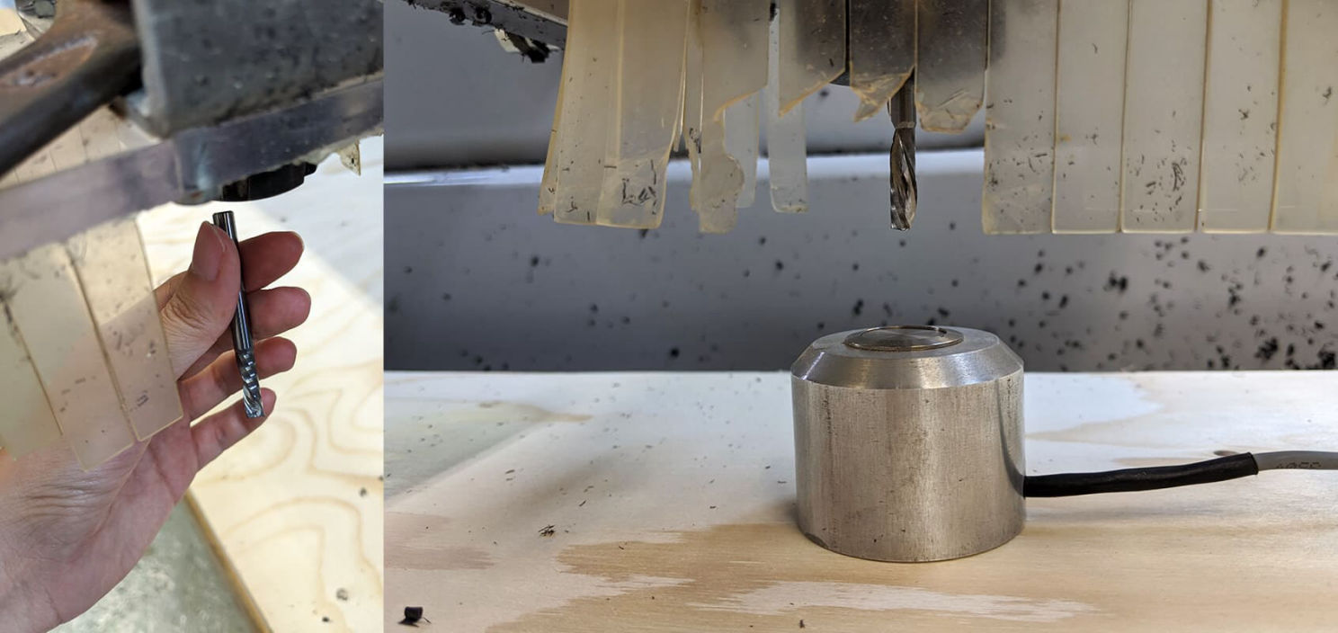
Then we are going to move the X and Y to a place where we can calibrate the Z, it is recommended not to do it in the corner, because sometimes this place is lifted a bit.
We put the length probe right under the end mill (it is very important to be sure it is right under it) and then we run the "Z0-finder with mobile tool length probe" script in the software. This will make the Z axis to lower down until it reached the probe, and it will automatically set the Z axis.
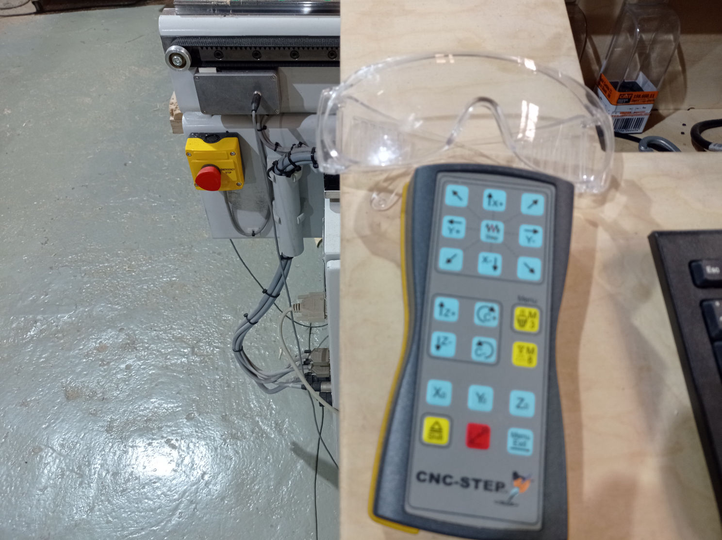

CNC is like a gigantic drill moving pretty fast, scrapping some material with a metallic end mill, and therefore, it could make some material splinters to fly towards you or in the worst case, the end mill could break at a really fast speed by hitting a screw or something else, and it could fly directly into your eyes, so it is recommended to always use safety glasses.

The CNC is a really strong (and expensive) machine, and therefore dangerous. Something could go wrong, like the broken end mill we where talking about, or someones shirt could get trapped in the chains of the gantry and pull him, or it should hit someone really fast. That's why you should always keep an eye on it(with safety glasses on as we said) and stand in front of the emergency stop button so you can quickly stop it in case anything goes wrong. This CNC has two emergency's button's, in opposite corners, one of them close to where we turn it on and control it (X-0,Y-0).

Page was started with Mobirise